Table of Contents
Advertisement
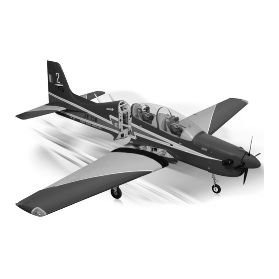
TUCANO 60CC
SPECIFICATION
- Wingspan: 2567mm (101in)
- Length: 2190mm (86.2 in)
- Flying weight: 11-13 kg
- Wing area: 101 dm2
- Wing loading: 99g/dm2
- Wing type: Naca airfoils
- Covering type: Genuine ORACOVER®
- Retract gear type: Air-retract With CNC
Suspension Metal Struts (included)
- Spinner size: 115mm (included)
- Radio: 6 channel minimum (not included)
- Servo: 10 standard hi-torque servo: 2 aileron;
2 ap; 2 elevator; 1 rudder;1 retract; 1 throttle;
1 steering nose. (not included)
- Recommended receiver battery:
6.0V 2400/2600mAh NiMH (2) (not included)
- Servo mount: 21mm x 42 mm
- Propeller: suit with your engine
Instruction Manual
SCALE 1:4 ¼ ARF
- Engine: 50- 60 CC gas engine (two stroke)
(not included)
- Motor: brushless outrunner 2600-3000 W,
190 KV (not included)
- Gravity CG: 141 mm (5.5 in) Back from the
leading edge of the wing, at the fuselage
- Control throw Ailerons: Low: 12mm up/down,
10% expo; High: 15mm up/down, 10% expo
- Control throw Elevators: Low: 12mm up/down,
12% expo; High: 15mm up/down, 12% expo
- Control throw Rudder: Low: 30mm right/left,
15% expo; High: 45mm right/left, 15% expo
- Control throw Flaps: Mid: 25mm down;
Landing: 35mm down
- Experience level: Intermediate
- Plane type: Scale Military
RECOMMENDED MOTOR AND BATTERY SET UP
- Motor: Hacker A60 (not included)
- Propeller: 22x10 E; 22x12 E APC (not included)
- Lipo cell: 12 cells / 5500 – 6000mAh (not included)
- Esc: 120-160A / HV (not included)
GP
EP
version
version
Advertisement
Table of Contents

Related Manuals for Phoenix Model TUCANO 60CC


Summary of Contents for Phoenix Model TUCANO 60CC
- Page 1 Instruction Manual version version TUCANO 60CC SCALE 1:4 ¼ ARF SPECIFICATION - Engine: 50- 60 CC gas engine (two stroke) (not included) - Wingspan: 2567mm (101in) - Motor: brushless outrunner 2600-3000 W, - Length: 2190mm (86.2 in) 190 KV (not included) - Flying weight: 11-13 kg - Gravity CG: 141 mm (5.5 in) Back from the...
- Page 2 This will assure proper assembly. The Use a covering iron with a covering sock on TUCANO 60CC SCALE 1:4 ¼ ARF is hand made high heat to tighten the covering if necessary. from natural materials, every plane is unique and...
- Page 3 TUCANO 60CC Instruction Manual INSTALLING THE AILERONs AND FLAPs 4. Using the thread as a guide and using masking tape, tape the servo lead to the end of the SERVOS thread: carefully pull the thread out. When you have pulled the servo lead out, remove the 1.
- Page 4 TUCANO 60CC Instruction Manual 2x10mm 2x10mm Warning! Set all scerws securely. If they come off during flight you will lose control of your aircraft! 2x10mm Tie the string. Pull out servo cord with string.
- Page 5 TUCANO 60CC Instruction Manual INSTALLING THE AILERONs AND FLAPs LINKAGES 3 x 12mm Screw Nylon Nut 3mm Washer 3 x 25mm Cap Screw 3x25mm Aluminum ball 3 x 85mm Push rod Aileron Flap < Bottom view > Neutral Cut away film only here.
- Page 6 TUCANO 60CC Instruction Manual Aluminum ball 3x12mm 3x12mm Aileron Flap < Bottom view > Apply threadlocker (screw cement).
- Page 7 TUCANO 60CC Instruction Manual INSTALLING THE MAIN LANDING GEAR 6 x 45mm Cap Screw 12x10mm Collar 4x4mm 4x4mm Set Screw Apply threadlocker (screw cement).
- Page 8 TUCANO 60CC Instruction Manual Air Hose Spring Air Hose...
- Page 9 TUCANO 60CC Instruction Manual Air Hose Air Hose Spring SUPERLOCK AIR RETRACTS 7kg /cm AIR PUMP AIR SUPPLY VALVE ONE WAY 3 WAY MAIN GEAR CONNECTOR NOSE GEAR VALVE CONTROL 4 WAY CONNECTOR MAIN GEAR SERVO AIR TANK 4 WAY CONNECTOR...
- Page 10 TUCANO 60CC Instruction Manual < Wheel well > Assemble left and right Pay close attention here! sides the same way Apply epoxy glue Cut off shaded portion...
- Page 11 TUCANO 60CC Instruction Manual 4 x 20mm Cap Screw 4mm Washer 4x20mm 4mm Spring Washer 4x20mm Assemble left and right sides the same way...
- Page 12 TUCANO 60CC Instruction Manual Aluminum ball 3 x 12mm Screw 3 x 30mm Push rod Nylon Nut Metal Strap 3mm Washer 3x8mm Button Screw 3x12mm Metal Strap Metal Strap 3x12mm Apply threadlocker (screw cement). Cut off shaded portion Assemble left and right...
- Page 13 TUCANO 60CC Instruction Manual 3x12mm Metal Strap 3x12mm 3x12mm Metal Strap 3x12mm Assemble left and right sides the same way.
- Page 14 TUCANO 60CC Instruction Manual 3x12mm 3x12mm Ensure smooth, non-binding movement when assembling Apply threadlocker (screw cement). Assemble left and right sides the same way.
- Page 15 TUCANO 60CC Instruction Manual 6x45mm Plastic Screw Joiner 6x45mm 6x45mm 4x20mm 4x30mm Plastic Screw 4 x 20mm Cap Screw 4mm Washer Plate of plywood 4mm Spring Washer 4x30mm Apply instant glue (CA glue, super glue). Bomb Cut off shaded portion...
- Page 16 TUCANO 60CC Instruction Manual SECURE The Wing To The Fuselage 6x45mm Plastic Screw Attach the wings to the joiner tube and secure the wing panels to the fuselage. 6x45mm Assemble left and right sides the same way.
- Page 17 TUCANO 60CC Instruction Manual INSTALLING THE ELEVATOR SERVO INSTALLING THE ELEVATOR LINKAGES 1. Remove the covering from the horizontal . Repeat these step as installing the aileron stabilizer. linkages. 2. Install two servo to the horizontal stabilizer as shown. 3. Repeat these step as installing the aileron control horn .
- Page 18 TUCANO 60CC Instruction Manual 3x30mm 3x30mm 3x12mm Cut off shaded portion Assemble left and right Must be purchased separately! sides the same way.
- Page 19 TUCANO 60CC Instruction Manual Aluminum ball Aluminum ball 3x12mm Aluminum ball Elevator rod 3x12mm 3x12mm Aluminum ball Assemble left and right sides the same way Apply threadlocker (screw cement).
- Page 20 TUCANO 60CC Instruction Manual HORIZONTAL STABILIZER INSTALLATION RUDDER INSTALLATION Warning! Make certain plane is aligned accurately per the diagram. A mis-aligned plane can fly erraticaliy and cause accidents. Cut off shaded portion Assemble left and right sides the same way.
- Page 21 TUCANO 60CC Instruction Manual Plate of plywood Aluminum Apply instant glue (CA glue, super glue). INSTALLING THE RUDDER LINKAGES 5. Thread the metal connector to the link ball. The rudder is controlled by two metal cables. 6. Center the rudder servo using the radio and Install the rudder linkages and cables as below.
- Page 22 TUCANO 60CC Instruction Manual Set all screws securely. If they come off during flight you will lose control of your aircraft! Cable 3x12mm 3x35mm Cable rod Cable rod Cut off excess. Cut off excess. Pay close attention here Cut off shaded portion...
- Page 23 TUCANO 60CC Instruction Manual Pay close attention here...
- Page 24 TUCANO 60CC Instruction Manual INSTALLING THE NOSE GEAR RETRACT 4 x 30mm Cap Screw 6 x 45mm Cap Screw 4mm Washer 4x4mm Set Screw 4mm Spring Washer 4x4mm 12x7mm Collar 4x30mm 4x30mm Apply threadlocker (screw cement).
- Page 25 TUCANO 60CC Instruction Manual Cable rod Cable rod Cut off excess. Cut off shaded portion Must be purchased Pay close attention here separately!
- Page 26 TUCANO 60CC Instruction Manual INSTALLING THE AIR VALVE Nylon Strap Tighten firmly. Tighten firmly. Loosen nut.
- Page 27 TUCANO 60CC Instruction Manual Air Hose Air Hose Air Hose Air tank Air Hose Air Hose Air Hose...
- Page 28 TUCANO 60CC Instruction Manual Use linkage to push the piston in all the way. Keep the piston inside the - marked area. Air flow direction.
- Page 29 TUCANO 60CC Instruction Manual INSTALLING THE Fuel Tank 6. When satisfied with the alignment of the stopper assembly tighten the 3mm x 20mm machine 1. The stopper has been pre-assembled at the screw until the rubber stopper expands and factory.
- Page 30 TUCANO 60CC Instruction Manual INSTALLING THE ENGINE 3 x 300mm Choke rodt 3 x 210mm Throttle rod Silicone Throttle Silicone May be you also need to trim some wood from the tri-angle wood for the installation is easy. Choke rod...
- Page 31 TUCANO 60CC Instruction Manual DLE 61 CC DLE 61 CC Throttle Lever Silicone Silicone Choke Lever Must be purchased separately!
- Page 32 TUCANO 60CC Instruction Manual INSTALLING THE THROTTLE 1. Plug the throttle servo into the receiver and turn on the radio system. Check to ensure that the throttle servo output shaft is moving in the correct direction. When the throttle stick is moved forward from idle to full throttle, the throttle barrel should also open and close using this motion.
- Page 33 TUCANO 60CC Instruction Manual MOUNTING THE COWL 4. While holding the cowl firmly in position, drill 1,6mm pilot holes through both the cowl and the side edges of the firewall. 1. Remove the muffler and needle valve assembly from the engine. Slide the fiberglass cowl over the 5.
- Page 34 TUCANO 60CC Instruction Manual Must be purchased separately! INSTALLING THE SPINNER Install the spinner back-plate, propeller and spinner cone. The propeller should not touch any part of the spinner cone. If it dose, use a sharp modeling knife and carefully trim away the spinner cone where the propeller comes in contact with it.
- Page 35 TUCANO 60CC Instruction Manual INSTALLING THE RECEIVER AND BATTERY INSTALLING THE SWITCH 1. Plug the servo leads and the switch lead into the 1. The switch should be mounted on the fuselage receiver. You may want to plug an aileron...
- Page 36 TUCANO 60CC Instruction Manual HACKER BRUSHLESS Q80 16x5mm 5x40mm 12x15mm Mount Nut 12x35mm 5x60mm 12x35mm Must be purchased separately! Apply threadlocker (screw cement).
- Page 37 TUCANO 60CC Instruction Manual Velcro Battery Battery When rotating clock wise, change the connection of 2 wires. < Check the motor rotation > Must be purchased separately!
- Page 38 TUCANO 60CC Instruction Manual BALANCING 3. Turn the airplane upside down. Place your fingers 1. It is critical that your airplane be balanced correctly. on the masking tape and carefully lift the plane. Improper balance will cause your plane to lose 4.
- Page 39 TUCANO 60CC Instruction Manual FLIGHT PREPARATION PRE FLIGHT CHECK 12mm 12mm 1. Completely charge your transmitter and receiver batteries before your first day of flying. Aileron Control 2. Check every bolt and every glue joint in your plane to ensure that everything is tight and well bonded.
- Page 40 TUCANO 60CC Instruction Manual 45.0 Main Gear Dimensional Detail 33.0 45.0 Nose Gear Dimensional Detail 33.0...
- Page 41 16x5mm 5x40mm 12x15mm 3x15mm(TP) 12x35mm 4x20mm 5x60mm Mount Nut 3x10mm 3x10mm 4x20mm 4x20mm 4x20mm 4x20mm...
- Page 42 3x30mm 3x30mm 3x12mm 3x12mm 3x12mm 3x12mm 3x12mm 3x12mm 3x25mm 3x25mm Plate of plywood 3x12mm 3x12mm 6x45mm 2x10mm(TP) 2x10mm(TP) 4x30mm 3x35mm Cable rod Plate of plywood Aluminum 4x30mm 6x45mm 4x30mm 6x45mm 3x25mm 3x12mm 3x12mm 3x25mm 6x45mm 2x10mm(TP) 2x10mm(TP)
- Page 43 I/C FLIGHT WARNINGS Always operate in open areas, away Keep all onlookers (especially small from factories, hospitals, schools, THE PROPELLER IS DANGEROUS children and animals) well back from buildings and houses etc. NEVER fly Keep fingers, clothing (ties, shirt the area of operation. This is a flying your aircraft close to people or built sleeves, scarves) or any other loose aircraft, which will cause serious...
- Page 44 I/C FLIGHT GUIDELINES Operate the control sticks on the When ready to fly, first extend the transmitter and check that the control transmitter aerial. surfaces move freely and in the ALWAYS land the model INTO the CORRECT directions. wind, this ensures that the model lands at the slowest possible speed.
Need help?
Do you have a question about the TUCANO 60CC and is the answer not in the manual?
Questions and answers