Advertisement
Table of Contents
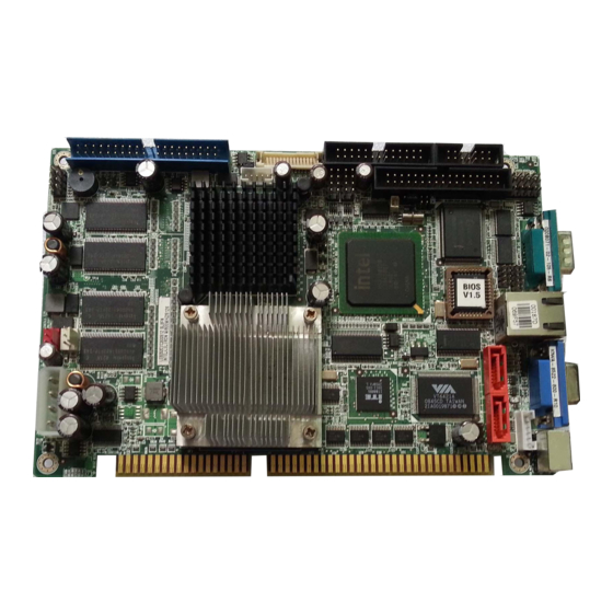
Half-Size ISA CPU Card with Intel® Pentium® M/
Celeron® M at 400MHz FSB, LVDS/CRT for Dual Display,
Quick Installation Guide
Package List
IOWA-8522 package includes the following items:
l
1 x IOWA-8522 single board computer
l
1 x mini jumper pack
l
1 x IDE Flat Cable
l
2 x SATA cable
l
1 x Dual RS -232 cable
l
1 x SATA Power cable
l
1 x KB/MS Y cable
l
1 x USB cable
l
1 x Utility CD
l
1 x QIG
LAN, SATA with RAID, USB2.0
IOWA-8522
Version 1.0
Jal. 5, 2011
©200 6 Copyright by IEI Technology corp.
All rights reserved.
1
Advertisement
Table of Contents

Related Manuals for IEI Technology IOWA-8522


Summary of Contents for IEI Technology IOWA-8522
-
Page 1: Quick Installation Guide
IOWA-8522 Quick Installation Guide Version 1.0 Jal. 5, 2011 Package List IOWA-8522 package includes the following items: 1 x IOWA-8522 single board computer 1 x mini jumper pack 1 x IDE Flat Cable 2 x SATA cable 1 x Dual RS -232 cable... -
Page 2: Specifications
Specifications Form Factor: Half Size ISA CPU Card CPU: Socket 479 Pentium M/ Celeron M at FSB 400MHz On board Celeron M 1.0GHz with 0K cache or Celeron M 600MHz with 512K cache System Chipset: Intel 852GM ICH4 BIOS: AMI BIOS Label Memory: 1 x 200-pin SO-DIMM socket DDR Memory up to 1GB On-board 128MB DDR Memory... -
Page 3: Ordering Information
Humidity: Operation:5%~95% non-condensing Dimension: 185mm x 122mm Weight: GW: 1.0Kg Ordering Information IOWA-8522-R10: Half Size ISA CPU Card with Intel® Pentium® M / Celeron® M at 400MHz FSB, LVDS/CRT for Dual Display, LAN, SATA with RAID, USB2.0 IOWA-8522-1GZ-R10: Half Size ISA CPU Card with Intel® Celeron M 1GHz / Zero Cache, LVDS/CRT for Dual Display, LAN, SATA with RAID, USB2.0... -
Page 4: Jumpers Setting And Connectors
Jumpers setting and Connectors JP1 : configure COM2 Mode J_CMOS1 : Clear CMOS Setup DESCRIPTION J_CMOS1 DESCRIPTION Short 1-2 RS - 232 Short 1-2 Keep CMOS Setup (default) (default)* (Normal Operation) Short 3-4 RS - 422 Short 2-3 Clear CMOS Setup Short 5-6 RS - 485 J_VLVDS1 : LVDS Voltage Selection... - Page 5 IDE1 : IDE Interface Connector DESCRIPTION DESCRIPTION RESET# DATA 7 DATA 8 DATA 6 DATA 9 DATA 5 DATA 10 DATA 4 DATA 11 DATA 3 DATA 12 DATA 2 DATA 13 DATA 1 DATA 14 DATA 0 DATA 15 IDE DRQ IOW# IOR#...
- Page 6 LPT1: LPT Connector DESCRIPTION DESCRIPTION STROBE# AUTO FORM FEED # DATA0 ERROR# DATA1 INITIALIZE# DATA2 PRINTER SELECT LN# DATA3 DATA4 DATA5 DATA6 DATA7 ACKNOWLE DGE# BUSY PAPER EMPTY PRINTER SELECT COM2: 14-pin internal connector Connector Ports Address Interrupt COM2 COM2 IRQ3 COM2 : Internal Serial Port Connector DESCRIPTION...
- Page 7 DIO1 : Digital Input / Output Connector DESCRIPTION DESCRIPTION Ground Output 3 Output 2 Output 1 Output 0 Input 3 Input 2 Input 1 Input 0 INVERTER1 : 5-pin Header Inverter Connector DESCRIPTION LCD_BKLTCTL GROUND +12V GROUND BACKLIGHT ENABLE USB01 & USB23 : Internal USB Connector DESCRIPTION DESCRIPTION DATA-...
- Page 8 LVDS1 : LVDS 2 Channel PWR1 : ATX POWER IN Connector DESCRIPTION Pin number : Pin number : +12V Pin name Pin name Pin-2 Pin-1 Pin-4 Pin-3 LVDSA_Y0- LVDSA_Y0+ Pin-6 Pin-5 IR1: IrDA connector LVDSA_Y1- LVDSA_Y1+ DESCRIPTION Pin-8 Pin-7 LVDSA_Y2- LVDSA_Y2+ Pin-10 : Pin-9...
- Page 9 Board Layout: Jumper and Connector Locations (Unit:MM)
Need help?
Do you have a question about the IOWA-8522 and is the answer not in the manual?
Questions and answers