Table of Contents
Advertisement
Quick Links
Advertisement
Table of Contents

Related Manuals for IEI Technology IOWA-8522


Summary of Contents for IEI Technology IOWA-8522
- Page 1 IOWA-8522 Motherboard Page i...
- Page 2 IOWA-8522 Motherboard Revision Date Revision Changes November 2007 1.00 Initial Release Page ii...
- Page 3 IOWA-8522 Motherboard Copyright COPYRIGHT NOTICE The information in this document is subject to change without prior notice in order to improve reliability, design and function and does not represent a commitment on the part of the manufacturer. In no event will the manufacturer be liable for direct, indirect, special, incidental, or consequential damages arising out of the use or inability to use the product or documentation, even if advised of the possibility of such damages.
- Page 4 Cautionary messages should also be heeded to help reduce the chance of losing data or damaging the IOWA-8522. Cautions are easy to recognize. The word “caution” is written as “CAUTION,” both capitalized and bold and is followed. The text is the cautionary message.
- Page 5 “NOTE,” both capitalized and bold and is followed by text. The text is the cautionary message. A note message is shown below: NOTE: This is an example of a note message. Notes should always be read. Notes contain critical information about the IOWA-8522. Please take note messages seriously. Page v...
-
Page 6: Packing List
IEI sales representative directly. To contact an IEI sales representative, please send an email to sales@iei.com.tw. The items listed below should all be included in the IOWA-8522 motherboard package. 1 x IOWA-8522 Single Board Computer 1 x Mini Jumper Pack... -
Page 7: Table Of Contents
IOWA-8522 Motherboard Table of Contents INTRODUCTION..................... 1 1.1 INTRODUCTION ....................2 1.2 BENEFITS........................ 2 1.3 FEATURES....................... 3 1.4 OVERVIEW......................3 1.5 PERIPHERAL CONNECTORS AND JUMPERS........... 5 1.6 TECHNICAL SPECIFICATIONS................6 DETAILED SPECIFICATIONS ................9 2.1 OVERVIEW......................10 2.2 DIMENSIONS......................10 2.2.1 Board Dimensions.................... - Page 8 IOWA-8522 Motherboard 2.7.2.2 Infrared...................... 24 2.7.2.3 Hardware Monitor Functions..............24 2.7.2.4 Parallel Port....................24 2.7.2.5 Keyboard and Mouse Controller............... 25 2.7.2.6 Digital I/O Ports..................26 2.7.2.7 Serial Ports ....................26 2.7.2.8 Floppy Disk Drive..................27 2.7.2.9 Fan Speed and Fan Control............... 28 2.8 PCI BUS COMPONENTS ..................
- Page 9 IOWA-8522 Motherboard 4.2.6 CompactFlash® Socket..................48 4.2.7 CPU Fan Connector ..................51 4.2.8 Digital Input/Output (DIO) Connector............52 4.2.9 Floppy Disk Connector (34-pin)..............53 4.2.10 Front Panel Connector (8-pin) ..............55 4.2.11 IDE Connector(40-pin) .................. 56 4.2.12 Infrared Interface Connector (5-pin) ............. 58 4.2.13 Keyboard/Mouse Connector ................
- Page 10 IOWA-8522 Motherboard 5.5 CHASSIS INSTALLATION................... 92 5.5.1 Airflow......................92 5.5.2 Motherboard Installation................. 93 5.6 INTERNAL PERIPHERAL DEVICE CONNECTIONS........93 5.6.1 Audio Kit Installation (Optional)..............94 5.6.2 IDE Cable Connection..................95 5.6.3 LVDS LCD Installation ..................96 5.6.4 Dual RS-232 Cables..................98 5.6.5 SATA Drive Connection ...................
- Page 11 IOWA-8522 Motherboard 6.3.8.1 USB Mass Storage Device Configuration..........137 6.4 PCI/PNP........................ 139 6.5 BOOT........................141 6.5.1 Boot Settings Configuration................142 6.5.2 Boot Device Priority ..................146 6.5.3 Hard Disk Drives, Removable Drives and CD/DVD Drives ......147 6.6 SECURITY ......................149 6.7 CHIPSET ......................
- Page 12 IOWA-8522 Motherboard E.2 COMPATIBLE PROCESSORS ................206 E.3 COMPATIBLE MEMORY MODULES .............. 207 HAZARDOUS MATERIALS DISCLOSURE ........... 209 F.1 HAZARDOUS MATERIAL DISCLOSURE TABLE FOR IPB PRODUCTS CERTIFIED AS ROHS COMPLIANT UNDER 2002/95/EC WITHOUT MERCURY ............................. 210 AC’97 AUDIO CODEC..................213 G.1 INTRODUCTION ....................
- Page 13 IOWA-8522 Motherboard List of Figures Figure 1-1: IOWA-8522 ....................2 Figure 1-2: IOWA-8522 Main View ................4 Figure 1-3: IOWA-8522 Solder Side ................4 Figure 2-1: Dimensions (mm)..................10 Figure 2-2: External Interface Panel Dimensions (mm)...........11 Figure 2-3: Data Flow Block Diagram................12 Figure 2-4: CPU ......................13 Figure 2-5: Intel®...
- Page 14 Figure 4-18: SATA Drive Connector Locations ............64 Figure 4-19: RS-232/422/485 Serial Port Connector Location ........65 Figure 4-20: USB Connector Pinout Locations ............67 Figure 4-21: IOWA-8522 External Peripheral Connector Panel ......68 Figure 4-22: PS/2 Pinout and Configuration.............69 Figure 4-23: Ethernet Connector ................70 Figure 4-24: COM1 Pinout Locations ................72...
- Page 15 IOWA-8522 Motherboard Figure 5-9: Jumper Locations..................86 Figure 5-10: Clear CMOS Jumper ................88 Figure 5-11: COM 2 Function Select Jumper Location ...........89 Figure 5-12: LVDS Voltage Selection Jumper Pinout Locations......91 Figure 5-13: LVDS Screen Resolution Selection Jumper Pinout Locations ..92 Figure 5-14: Audio Kits ....................95 Figure 5-15: IDE Cable Connection ................96...
- Page 16 IOWA-8522 Motherboard Figure 7-17: Select the Operating System Folder..........168 Figure 7-18: Select the Driver Version ..............169 Figure 7-19: Select the Installation File..............169 Figure 7-20: Network Adapter Welcome ..............170 Figure 7-21: Network Adapter License Agreement..........170 Figure 7-22: Network Adapter Setup Options ............171 Figure 7-23: Network Adapter Begin Installation..........
- Page 17 IOWA-8522 Motherboard Figure 7-49: VIA® RAID Driver Installation Complete .......... 186 Page xvii...
- Page 18 IOWA-8522 Motherboard List of Tables Table 1-1: Technical Specifications ................7 Table 2-1: Supported HDD Specifications ..............19 Table 2-2: Power Consumption .................34 Table 3-1: Package List Contents................38 Table 3-2: Optional Components................38 Table 4-1: Peripheral Interface Connectors..............42 Table 4-2: External Peripheral Interface Panel Connectors........42 Table 4-3: +12V Power Connector Pinouts...............43...
- Page 19 IOWA-8522 Motherboard Table 4-23: Ethernet Connector LEDs...............71 Table 4-24: RS-232 Serial Port (COM 1) Pinouts ............71 Table 4-25: VGA Connector Pinouts .................72 Table 5-1: Jumpers......................87 Table 5-2: Clear CMOS Jumper Settings ..............88 Table 5-3: COM 2 Function Select Jumper Settings..........89 Table 5-4: LVDS Voltage Selection Jumper Settings ..........90...
- Page 20 IOWA-8522 Motherboard List of BIOS Menus BIOS Menu 1: Main....................110 BIOS Menu 2: Advanced..................112 BIOS Menu 3: CPU Configuration................113 BIOS Menu 4: IDE Configuration ................114 BIOS Menu 5: IDE Master and IDE Slave Configuration........116 BIOS Menu 6: IDE Master and IDE Slave Configuration........121 BIOS Menu 7: Super IO Configuration ..............
-
Page 21: Introduction
IOWA-8522 Motherboard Chapter Introduction Page 1... -
Page 22: Introduction
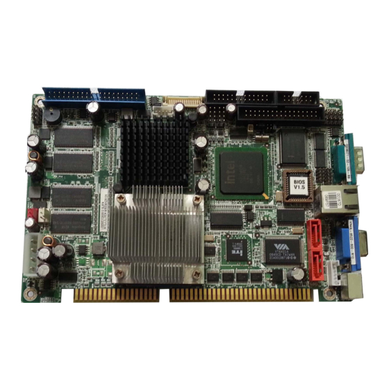
1.1 Introduction Figure 1-1: IOWA-8522 The IOWA-8522 is a half-size ISA CPU card with an embedded Intel® Celeron CPU or a socket 479 interface supporting Intel® Pentium® M and Intel® Celeron M processors. The IOWA-8522 features an Intel® 852GM Northbridge and Intel® I/O Controller Hub 4 (ICH4) Southbridge. -
Page 23: Features
Integrated 5.1 channel audio 1.4 Overview The IOWA-8522 has a wide variety of internal and external peripheral connectors. The peripheral connectors are connected to devices including storage devices, display devices and parallel communications devices. A labeled photo of the peripheral connectors is shown in Figure 1-1. -
Page 24: Figure 1-2: Iowa-8522 Main View
IOWA-8522 Motherboard Figure 1-2: IOWA-8522 Main View Figure 1-3: IOWA-8522 Solder Side Page 4... -
Page 25: Peripheral Connectors And Jumpers
1 x Parallel port connector 1 x Serial port connector 2 x USB connectors 2 x SATA connectors The IOWA-8522 has the following connectors on the rear panel: 1 x Ethernet connector 1 x PS/2 keyboard/mouse connector 1 x Serial port connector... -
Page 26: Technical Specifications
IOWA-8522 Motherboard 1.6 Technical Specifications IOWA-8522 technical specifications are listed in Table 1-1. Detailed descriptions of each specification can be found in Chapter 2. Specification IOWA-8522 Form Factor Half-size CPU card Embedded CPUs: Intel® Celeron M 600MHz (Banias Core) Intel® Celeron M 1GHz (Dothan Core) -
Page 27: Table 1-1: Technical Specifications
IOWA-8522 Motherboard Specification IOWA-8522 One 40-pin IDE connects to up to two Ultra ATA33/66/100 devices SATA Two 1.5Gb/s SATA drives supported One PS/2 port supports mouse and keyboard connectivity Keyboard/mouse One internal keyboard connector Watchdog Timer Software programmable 1-255 sec. by super I/O 5 V @ 5.29 A, 12V @ 0.13 A... -
Page 28: This Page Is Intentionally Left Blank
IOWA-8522 Motherboard THIS PAGE IS INTENTIONALLY LEFT BLANK Page 8... -
Page 29: Detailed Specifications
IOWA-8522 Motherboard Chapter Detailed Specifications Page 9... -
Page 30: Overview
IOWA-8522 Motherboard 2.1 Overview This chapter describes the specifications and on-board features of the IOWA-8522 in detail. 2.2 Dimensions 2.2.1 Board Dimensions The dimensions of the board are listed and shown below. Length: 185 mm Width: 122 mm Figure 2-1: Dimensions (mm) -
Page 31: External Interface Panel Dimensions
IOWA-8522 Motherboard 2.2.2 External Interface Panel Dimensions External peripheral interface connector panel dimensions are shown in Figure 2-2. Figure 2-2: External Interface Panel Dimensions (mm) Page 11... -
Page 32: Data Flow
IOWA-8522 Motherboard 2.3 Data Flow Figure 2-3 shows the data flow between the on-board chipsets and other components installed on the motherboard and described in the following sections of this chapter. Figure 2-3: Data Flow Block Diagram Page 12... -
Page 33: Compatible Processors
IOWA-8522 Motherboard 2.4 Compatible Processors Figure 2-4: CPU The IOWA-8522 comes preinstalled with an Intel® Celeron M 600MHz (Banias Core), an Intel® Celeron M 1GHz (Dothan Core) or a Socket 479 CPU socket for Intel® Pentium M and Celeron M processors. -
Page 34: Intel 852Gm Memory Support
IOWA-8522 Motherboard ® 2.5.1 Intel 852GM Memory Support The Intel® 852GM comes with 128 MB of DDR RAM onboard. The onboard memory is shown in Figure 2-6: Figure 2-6: Onboard DDR RAM The Intel® 852GM also supports one 200-pin DDR SO-DIMM with the following features:... -
Page 35: Intel 852Gm Display And Graphics Support
IOWA-8522 Motherboard ® 2.5.2 Intel 852GM Display and Graphics Support The Intel® 852GM Northbridge chipset has an integrated graphics engine that supports the following display devices: Analog CRT displays 18-bit dual channel LVDS Figure 2-7: Display and Graphics Support 2.5.2.1 Analog CRT The onboard Intel®... -
Page 36: Intel 852Gm Internal Graphics Controller
IOWA-8522 Motherboard 0.5%, 1%, and 2.5% utilizing an external SSC clock. The display pipe provides panel up- scaling to fit a source image into a specific panel size as well as panning and centering support. The LVDS port is only supported on Pipe B. The LVDS port can only be driven on Pipe B, either independently or simultaneously with the DAC port. -
Page 37: Intel 82801Db I/O Controller Hub (Ich4)
IOWA-8522 Motherboard Rotate, scale and translate operations High-performance 3D: 256-bit internal path 32bpp/ 24ZorW/ 8 Stencil DX7*/DX8*/OGL*1.1 DXTn texture compression Up to 4 textures / pixel on a single pass Cubic reflection map Embossed/DOT3 bump mapping Multi-texture DOT3 bump-mapping Point sprites... -
Page 38: Ide Interface
IDE HDDs. Two IDE devices can be connected to the primary IDE channel through the IDE header on the IOWA-8522. The CompactFlash® slot on the solder side of the IOWA-8522 is implemented through the secondary IDE channel. -
Page 39: Ac'97 Controller
Table 2-1: Supported HDD Specifications 2.6.2 AC’97 Controller The IOWA-8522 has an AC’97 controller interface. The interface can be connected to an optional audio kit. The optional audio kit provides audio output through its onboard Realtek ALC655 audio codec Figure 2-10. - Page 40 IOWA-8522 Motherboard 12.288MHz BITCLK input Interrupt capability Three analog line-level stereo inputs with 5-bit volume control, LINE_IN, CD, High-quality differential CD input Two analog line-level mono inputs: PCBEEP, PHONE-IN Two software selectable MIC inputs Dedicated Front-MIC input for front panel applications (software selectable) Boost preamplifier for MIC input LINE input shared with surround output;...
-
Page 41: Usb Controller
IOWA-8522 Motherboard 2.6.3 USB Controller The Intel® ICH4 supports six USB ports. Four USB ports are implemented through pin headers on the IOWA-8522. Figure 2-11: USB The chipset USB controller has the following specifications: Six USB ports (four implemented) USB 1.1 and USB 2.0 compliant... -
Page 42: Lpc Bus Components
IOWA-8522 Motherboard BIOS chipset Super I/O chipset 2.7 LPC Bus Components The LPC bus is connected to components listed below: BIOS chipset Winbond W83627EHG Super I/O chipset 2.7.1 BIOS Chipset The BIOS chipset has a licensed copy of AMI BIOS installed on the chipset. -
Page 43: Super I/O Chipset
IOWA-8522 Motherboard 2.7.2 Super I/O chipset The Winbond W83627EHG Super I/O chipset is connected to the ICH4 Southbridge through the LPC bus. Figure 2-13: Super I/O Chipset The Winbond W83627EHG is an LPC interface-based Super I/O device that comes with Environment Controller integration, floppy disk controller, UART controller and IR controller. -
Page 44: Infrared
IOWA-8522 Motherboard 2.7.2.2 Infrared The onboard Super I/O supports the following infrared specifications: IrDA version 1.0 SIR protocol with a maximum baud rate up to 115.2Kbps The IR controller on the super I/O is interfaced through the IrDA pin-header Figure 2-14: Infrared 2.7.2.3 Hardware Monitor Functions... -
Page 45: Keyboard And Mouse Controller
IOWA-8522 Motherboard The parallel port controller is connected to an external DB-26 LPT connector. Figure 2-15: Parallel Port 2.7.2.5 Keyboard and Mouse Controller The Super I/O keyboard and mouse controller is compatible with the following specifications. 8042 compatible Asynchronous access to two data registers and one status register... -
Page 46: Digital I/O Ports
IOWA-8522 Motherboard Figure 2-16: Keyboard and Mouse 2.7.2.6 Digital I/O Ports The Super I/O has a 10-pin, 8-bit programmable digital input/output port. Figure 2-17: Intel® 852GM 2.7.2.7 Serial Ports The on-board Super I/O has two integrated 16C550 UARTs that can support the... -
Page 47: Floppy Disk Drive
IOWA-8522 Motherboard 48 programmable general purpose I/O ports Figure 2-18: Super I/O Serial Ports 2.7.2.8 Floppy Disk Drive The Super I/O FDD controller is compatible with the following specifications. IBM PC AT disk drive compatible Variable write pre-compensation with track selectable capability... -
Page 48: Fan Speed And Fan Control
IOWA-8522 Motherboard 1Mbps 2Mbps 3-mode FDD and Win95/98 driver supported The FDD controller is interfaced to a FDD connected to the backplane through the board- to-board connectors. Figure 2-19: Super I/O Floppy Disk Drive Controller 2.7.2.9 Fan Speed and Fan Control The super I/O can monitor the fan speed. -
Page 49: Pci Bus Components
IOWA-8522 Motherboard 2.8 PCI Bus Components Figure 2-20: PCI Interface The PCI bus is connected to one of the two components listed below: Intel® EP82562ET Ethernet controller VIA® VT6421A SATA controller ITE PCI-to-ISA chipset The PCI bus complies with PCI Local Bus Specification, Revision 2.2, supports 33MHz PCI operations and 133MBps maximum throughput. -
Page 50: Intel® Ep82562Et Ethernet Controller
IOWA-8522 Motherboard 2.8.1 Intel® EP82562ET Ethernet Controller The Intel® 82562ET is an IEEE 10BASE-T and 100BASE-TX Ethernet controller that connects the Southbridge chipset to the LAN RJ-45 connector. The Intel® 82562ET is designed for 10Mbps or 100Mbps Ethernet systems. Figure 2-21: Ethernet Controller Some features of the Intel®... -
Page 51: Via® Vt6421A Sata Drive Controller
IOWA-8522 Motherboard 2.8.2 VIA® VT6421A SATA Drive Controller A VIA® VT6421A SATA drive controller is connected to two SATA drive connectors and interfaced to the system through the PCI bus. Figure 2-22: SATA Drive Controller The VIA® VT6421A SATA drive controller has the following features:... -
Page 52: Ite It8888G Pci-To-Isa Bridge
IOWA-8522 Motherboard 2.8.3 ITE IT8888G PCI-to-ISA Bridge An ITE IT8888G PCI to ISA bridge single function device enables legacy ISA card expansion on the backplane. The PCI to ISA bridge is shown in Figure 2-23. Figure 2-23: PCI-to-ISA Bridge The IT8888G has a PCI specification v2.1 compliant 32-bit PCI bus interface and supports both PCI Bus master and slave. -
Page 53: Environmental And Power Specifications
+3.3V PCI I/F with +5V tolerant I/O buffers +5V ISA I/F and core Power Supply 2.9 Environmental and Power Specifications 2.9.1 System Monitoring Three thermal inputs on the IOWA-8522 Super I/O Enhanced Hardware Monitor monitors the following temperatures: System temperature CPU temperature... -
Page 54: Power Consumption
CPU. A heat sink is also mounted on the Northbridge chipset to ensure the operating temperature remains low. 2.9.3 Power Consumption Table 2-2 shows the power consumption parameters for the IOWA-8522 running with a 2.0 GHz Intel® Pentium® M processor and 1 GB DDR RAM. Voltage Current 5.29 A... -
Page 55: Unpacking
IOWA-8522 Motherboard Chapter Unpacking Page 35... -
Page 56: Anti-Static Precautions
When the IOWA-8522 is unpacked, please do the following: Follow the anti-static precautions outlined in Section 3.1. Make sure the packing box is facing upwards so the IOWA-8522 does not fall out of the box. Make sure all the components shown in Section 3.3 are present. -
Page 57: Unpacking Checklist
If some of the components listed in the checklist below are missing, please do not proceed with the installation. Contact the IEI reseller or vendor you purchased the IOWA-8522 from or contact an IEI sales representative directly. To contact an IEI sales representative, please send an email to sales@iei.com.tw. -
Page 58: Optional Components
IOWA-8522 Motherboard Quantity Item and Part Number Image SATA power cable (P/N: 32100-088600-RS) Dual RSS-232 (w/o bracket) (P/N: 19800-000051-RS) Mini jumper Pack Quick Installation Guide Utility CD Table 3-1: Package List Contents 3.3.2 Optional Components The following components are optional:... -
Page 59: Connector Pinouts
IOWA-8522 Motherboard Chapter Connector Pinouts Page 39... -
Page 60: Peripheral Interface Connectors
IOWA-8522 Motherboard 4.1 Peripheral Interface Connectors Section 4.1.1 shows peripheral interface connector locations. Section 4.1.2 lists all the peripheral interface connectors seen in Section 4.1.1. 4.1.1 Layout Figure 4-2 shows the on-board peripheral connectors, rear panel peripheral connectors and on-board jumpers. -
Page 61: Peripheral Interface Connectors
IOWA-8522 Motherboard Figure 4-2: Solder Side Connector and Jumper Locations 4.1.2 Peripheral Interface Connectors Table 4-2 shows a list of the peripheral interface connectors on the IOWA-8522. Detailed descriptions of these connectors can be found below. Connector Type Label AT power connector... -
Page 62: External Peripheral Interface Panel Connectors
USB connector 8-pin header USB23 Table 4-1: Peripheral Interface Connectors 4.1.3 External Peripheral Interface Panel Connectors Table 4-3 lists the external peripheral interface panel connectors on the IOWA-8522. Detailed descriptions of these connectors can be found in. Connector Type Label... -
Page 63: Internal Peripheral Connectors
Internal peripheral connectors are found on the motherboard and are only accessible when the motherboard is outside of the chassis. This section has complete descriptions of all the internal, peripheral connectors on the IOWA-8522. 4.2.1 Power Supply Connector CN Label:... -
Page 64: Atx Power Supply Enable Connector
The ATX power supply enable connector enables the IOWA-8522 to be connected to an ATX power supply. In default mode, the IOWA-8522 can only us an AT power supply. To enable an ATX power supply the AT Power Select jumper must also be configured. -
Page 65: Audio Connector (10-Pin)
IOWA-8522 Motherboard 4.2.3 Audio Connector (10-pin) CN Label: J_AUDIO1 CN Type: 10-pin header CN Location: See Figure 4-5 CN Pinouts: See Table 4-5 The 9-pin audio connector is connected to an optional 5.1 channel audio kit. Figure 4-5: Audio Connector Pinouts (10-pin) PIN NO. -
Page 66: Backlight Inverter Connector
CN Location: See Figure 4-6 CN Pinouts: See Table 4-6 The backlight inverter connector provides the backlight on the LCD display connected to the IOWA-8522 with +12V of power. Figure 4-6: Panel Backlight Connector Pinout Locations PIN NO. DESCRIPTION BL_ADJ... -
Page 67: Battery Connector
IOWA-8522 Motherboard 4.2.5 Battery Connector CN Label: CN Type: 2-pin wafer (1x2) CN Location: See Figure 4-7 CN Pinouts: See Table 4-7 The battery connector is connected to a backup battery. The battery connector is also used to reset the CMOS memory if the incorrect BIOS settings have been made and the system cannot boot up. -
Page 68: Compactflash® Socket
CF1 (solder side) CN Type: 50-pin header (2x25) CN Location: See Figure 4-8 CN Pinouts: See Table 4-8 A CompactFlash® Type I or Type II memory card is inserted to the CF socket on the solder side of the IOWA-8522. Page 48... -
Page 69: Figure 4-8: Cf Card Socket Location
IOWA-8522 Motherboard Figure 4-8: CF Card Socket Location PIN NO. DESCRIPTION PIN NO. DESCRIPTION GROUND SDD3 SDD11 SDD4 SDD12 SDD5 SDD13 SDD6 SDD14 Page 49... -
Page 70: Table 4-8: Cf Card Socket Pinouts
IOWA-8522 Motherboard PIN NO. DESCRIPTION PIN NO. DESCRIPTION SDD7 SDD15 SDCS#1 SDCS#3 GROUND GROUND SDIOR# GROUND SDIOW# GROUND VCC5 GROUND IRQ15 VCC5 VCC5 GROUND Master/Slave Select GROUND GROUND IDERST# GROUND SIORDY SDA2 SDREQ SDA1 SDDACK# SDA0 IDEACTS# SDD0 SDD1 SDD8... -
Page 71: Cpu Fan Connector
IOWA-8522 Motherboard 4.2.7 CPU Fan Connector CN Label: CPU_FAN1 CN Type: 3-pin wafer connector CN Location: See Figure 4-9 CN Pinouts: See Table 4-9 The FAN1 cooling fan connector provides a 12V current to the cooling fan. The connector has a "rotation" pin to get rotation signals from the fan and notify the system so the system BIOS can recognize the fan speed. -
Page 72: Digital Input/Output (Dio) Connector
IOWA-8522 Motherboard 4.2.8 Digital Input/Output (DIO) Connector CN Label: DIO1 CN Type: 10-pin header (2x5) CN Location: See Figure 4-10 CN Pinouts: See Table 4-10 The digital input/output connector is managed through a Super I/O chip. The DIO connector pins are user programmable. -
Page 73: Floppy Disk Connector (34-Pin)
IOWA-8522 Motherboard 4.2.9 Floppy Disk Connector (34-pin) CN Label: FDD1 CN Type: 34-pin header (2x17) CN Location: See Figure 4-11 CN Pinouts: See Table 4-11 The floppy disk connector is connected to a floppy disk drive. Figure 4-11: 34-pin FDD Connector Location PIN NO. -
Page 74: Table 4-11: 34-Pin Fdd Connector Pinouts
IOWA-8522 Motherboard DIRECTION# STEP# WRITE DATA# WRITE GATE# TRACK 0# WRITE PROTECT# READ DATA# SIDE 1 SELECT# DISK CHANGE# Table 4-11: 34-pin FDD Connector Pinouts Page 54... -
Page 75: Front Panel Connector (8-Pin)
IOWA-8522 Motherboard 4.2.10 Front Panel Connector (8-pin) CN Label: F_PANEL1 CN Type: 8-pin header (2x4) CN Location: See Error! Reference source not found. CN Pinouts: See Error! Reference source not found. The front panel connector connects to external switches and indicators to monitor and controls the motherboard. -
Page 76: Ide Connector(40-Pin)
CN Type: 40-pin header (2x20) CN Location: See Figure 4-13 CN Pinouts: See Table 4-13 One 40-pin IDE connector on the IOWA-8522 supports connectivity to up to two IDE devices. Figure 4-13: IDE Device Connector Locations PIN NO. DESCRIPTION PIN NO. -
Page 77: Table 4-13: Ide Connector Pinouts
IOWA-8522 Motherboard PIN NO. DESCRIPTION PIN NO. DESCRIPTION DATA 0 DATA 15 GROUND N/C (KEY) IDE DRQ GROUND IOW# GROUND IOR# GROUND IDE CHRDY GROUND IDE DACK GROUND–DEFAULT INTERRUPT PCIAG# HDC CS0# HDC CS1# HDD ACTIVE# GROUND Table 4-13: IDE Connector Pinouts... -
Page 78: Infrared Interface Connector (5-Pin)
IOWA-8522 Motherboard 4.2.12 Infrared Interface Connector (5-pin) CN Label: CN Type: 5-pin header (1x5) CN Location: See Figure 4-14 CN Pinouts: See Table 4-14 The infrared interface connector supports consumer remote control frequencies, like those used in remote controls. Figure 4-14: Infrared Connector Pinout Locations... -
Page 79: Keyboard/Mouse Connector
IOWA-8522 Motherboard 4.2.13 Keyboard/Mouse Connector CN Label: CN Type: 6-pin header (1x6) CN Location: See Figure 4-15 CN Pinouts: See Table 4-15 The keyboard and mouse connector can be connected to a standard PS/2 cable or PS/2 Y-cable to add keyboard and mouse functionality to the system. -
Page 80: Lvds Lcd Connector
IOWA-8522 Motherboard 4.2.14 LVDS LCD Connector CN Label: LVDS1 CN Type: 30-pin crimp (2x10) CN Location: See Figure 4-16 CN Pinouts: See Table 4-16 The 30-pin LVDS LCD connector can be connected to single channel or dual channel, 18-bit or 36-bit LVDS panel. -
Page 81: Table 4-16: Lvds Lcd Port Connector Pinouts
IOWA-8522 Motherboard PIN NO. DESCRIPTION PIN NO. DESCRIPTION GROUND GROUND LVDSA_Y0+ LVDSA_Y0- LVDSA_Y1+ LVDSA_Y1- LVDSA_Y2+ LVDSA_Y2- LVDSA_CLK+ LVDSA_CLK- LVDSA_Y3+ LVDSA_Y3- GROUND GROUND LVDSB_Y0+ LVDSB_Y0- LVDSB_Y1+ LVDSB_Y1- LVDSB_Y2+ LVDSB_Y2- LVDSB_CLK+ LVDSB_CLK- LVDSB_Y3+ LVDSB_Y3- GROUND GROUND VCC_LVDS VCC_LVDS VCC_LVDS VCC_LVDS Table 4-16: LVDS LCD Port Connector Pinouts... -
Page 82: Parallel Port Connector
IOWA-8522 Motherboard 4.2.15 Parallel Port Connector CN Label: LPT1 CN Type: 26-pin box header CN Location: See Figure 4-17 CN Pinouts: See Table 4-17 The 26-pin parallel port connector connects to a parallel port connector interface or some other parallel port device such as a printer. -
Page 83: Table 4-17: Parallel Port Connector Pinouts
IOWA-8522 Motherboard DESCRIPTION DESCRIPTION RSTROBE# ALF# RPD0 ERROR# RPD1 PAR_INI# RPD2 SLCTIN# RPD3 GND1 RPD4 GND2 RPD5 GND3 RPD6 GND4 RPD7 GND5 ACK# GND6 BUSY GND7 GND8 SLCT Table 4-17: Parallel Port Connector Pinouts Page 63... -
Page 84: Sata Drive Connectors
IOWA-8522 Motherboard 4.2.16 SATA Drive Connectors CN Label: SATA1, SATA2 CN Type: 7-pin SATA drive connectors CN Location: See Figure 4-18 CN Pinouts: See Table 4-18 The SATA drive connectors are connected to SATA 1.5Gb/s disk drives that transfer data at speeds as high as 1.5Gb/s. -
Page 85: Serial Port Connector (Com2)(Rs-232, Rs-422 Or Rs-485)
IOWA-8522 Motherboard DESCRIPTION Table 4-18: SATA Drive Connector Pinouts 4.2.17 Serial Port Connector (COM2)(RS-232, RS-422 or RS-485) CN Label: COM2 CN Type: 14-pin header (2x7) CN Location: See Figure 4-19 CN Pinouts: See Table 4-19 The 14-pin serial port connector connects to the COM 2 serial communications channels. -
Page 86: Table 4-19: Rs-232/Rs-485 Serial Port Connector Pinouts
IOWA-8522 Motherboard PIN NO. DESCRIPTION PIN NO. DESCRIPTION NDCD2 NDSR2 NRX2 NRTS2 NTX2 NCTS2 NDTR2 NRI2 TXD485+ TXD485# RXD485+ RXD485# Table 4-19: RS-232/RS-485 Serial Port Connector Pinouts Page 66... -
Page 87: Usb Connectors
IOWA-8522 Motherboard 4.2.18 USB Connectors CN Label: USB01, USB23 CN Type: 8-pin header (2x4) CN Location: See Figure 4-20 CN Pinouts: See Table 4-20 The 2x4 USB pin connector provides connectivity to two USB 1.1 or two USB 2.0 ports. -
Page 88: External Peripheral Interface Connectors
IOWA-8522 Motherboard 4.3 External Peripheral Interface Connectors Figure 4-21 shows the IOWA-8522 external peripheral connector panel. The peripheral connectors on the panel can be connected to devices externally when the motherboard is installed in a chassis. The external peripheral connectors are:... -
Page 89: Keyboard/Mouse Connector
KB_MS1 CN Type: PS/2 CN Location: See Figure 4-22 CN Pinouts: See Table 4-21 The IOWA-8522 keyboard and mouse connector is a standard PS/2 connector. Figure 4-22: PS/2 Pinout and Configuration DESCRIPTION KB DATA MS DATA KB CLOCK MS CLOCK... -
Page 90: Ethernet Connector
IOWA-8522 Motherboard 4.3.2 Ethernet Connector CN Label: LAN1 CN Type: RJ-45 ports CN Location: See Figure 4-23 CN Pinouts: See Table 4-22 and Table 4-23 A 10/100 Mb/s connection can be made between the Ethernet connectors and a Local Area Network (LAN) through a network hub. -
Page 91: Serial Port Connector
IOWA-8522 Motherboard The RJ-45 Ethernet connector has two status LEDs, one green and one yellow. The green LED indicates activity on the port and the yellow LED indicates the port is linked (Table 4-23). SPEED LED LINK LED Status Description... -
Page 92: Vga Connector
IOWA-8522 Motherboard Figure 4-24: COM1 Pinout Locations 4.3.4 VGA Connector CN Label: VGA1 CN Type: HD-D-sub 15 Female connector CN Location: See Figure 4-21 CN Pinouts: See Figure 4-25 and Table 4-25 The standard HD-D-sub 15 female connector connects to a CRT or LCD monitor. -
Page 93: On-Board Jumpers
IOWA-8522 Motherboard 4.4 On-board Jumpers The IOWA-8522 has three on-board jumpers. Refer to Section 5.4 for jumper configuration settings. Page 73... - Page 94 IOWA-8522 Motherboard THIS PAGE IS INTENTIONALLY LEFT BLANK Page 74...
-
Page 95: Installation
IOWA-8522 Motherboard Chapter Installation Page 75... -
Page 96: Anti-Static Precautions
Electrostatic discharge (ESD) can cause serious damage to electronic components, including the IOWA-8522. Dry climates are especially susceptible to ESD. It is therefore critical that whenever the IOWA-8522, or any other electrical component is handled, the following anti-static precautions are strictly adhered to. -
Page 97: Installation Notices
Before and during the installation of the IOWA-8522 DO NOT do the following: DO NOT remove any of the stickers on the PCB board. These stickers are required for warranty validation. -
Page 98: Installation Checklist
IOWA-8522 Motherboard 5.2.2 Installation Checklist The following checklist is provided to ensure the IOWA-8522 is properly installed. All the items in the packing list are present (see Chapter 3) A CPU is installed A CPU cooling kit is properly installed... -
Page 99: Cpu, Cpu Cooling Kit And So-Dimm Installation
Running a CPU without a cooling kit may also result in injury to the user. The CPU, CPU cooling kit and DIMM are the most critical components of the IOWA-8522. If one of these component is not installed the IOWA-8522 cannot run. -
Page 100: Figure 5-1: Make Sure The Cpu Socket Retention Screw Is Unlocked
IOWA-8522 Motherboard Step 1: Unlock the CPU retention screw. When shipped, the retention screw of the CPU socket should be in the unlocked position. If it is not in the unlocked position, use a screwdriver to unlock the screw. See Figure 5-1. -
Page 101: Cooling Kit Installation
IOWA-8522 Motherboard Step 7: Lock the retention screw. Rotate the retention screw into the locked position. See Figure 5-2.Step 0: Figure 5-2: Lock the CPU Socket Retention Screw 5.3.2 Cooling Kit Installation Figure 5-3: Cooling Kit The CPU cooling kit (Figure 5-3) can be purchased separately. The cooling kit comprises a CPU heat sink and a cooling fan. -
Page 102: Figure 5-4: Cooling Kit Support Bracket
IOWA-8522 Motherboard thermal paste on the bottom of the heat sink. The thermal paste between the CPU and the heat sink is important for optimum heat dissipation. To install the cooling kit, please follow the steps below. Step 1: Align the support bracket. Remove the tape from the support bracket. From the solder side of the PCB, align the support bracket to the holes on the PCB. -
Page 103: Figure 5-5: Securing The Cooling Kit
IOWA-8522 Motherboard Figure 5-5: Securing the Cooling Kit Step 4: Tighten the screws. Use a screwdriver to tighten the four screws. Tighten each nut a few turns at a time and do not over-tighten the screws. Over tightening can cause damage to the CPU. -
Page 104: So-Dimm Installation
Figure 5-7. Figure 5-7: SO-DIMM Installation Step 1: Locate the SO-DIMM socket. Place the IOWA-8522 on an anti-static pad with the solder side facing up. Step 2: Align the SO-DIMM with the socket. The SO-DIMM must be oriented in such a way that the notch in the middle of the SO-DIMM must be aligned with the plastic bridge in the socket. -
Page 105: Cf Card Installation
The IOWA-8522 can support both CF Type I cards and CF Type II cards. For the complete specifications of the supported CF cards please refer to Chapter 2. To install the a CF card (Type 1 or Type 2) onto the IOWA-8522, please follow the steps below: Step 1: Locate the CF card socket. -
Page 106: Jumper Settings
Before the IOWA-8522 is installed in the system, the jumpers must be set in accordance with the desired configuration. The jumpers on the IOWA-8522 are listed in Table 5-1. Page 86... -
Page 107: Clear Cmos
Jumper Location: See Figure 5-10 If the IOWA-8522 fails to boot due to improper BIOS settings, the clear CMOS jumper clears the CMOS data and resets the system BIOS information. To do this, use the jumper cap to close pins 2 and 3 for a few seconds then reinstall the jumper clip back to pins 1 and 2. -
Page 108: Com 2 Function Select Jumper
IOWA-8522 Motherboard AT Power Select Description Short 1 - 2 Keep CMOS Setup Default Short 2 - 3 Clear CMOS Table 5-2: Clear CMOS Jumper Settings The location of the clear CMOS jumper is shown in Figure 5-10 below. Figure 5-10: Clear CMOS Jumper 5.4.2 COM 2 Function Select Jumper... -
Page 109: Figure 5-11: Com 2 Function Select Jumper Location
IOWA-8522 Motherboard COM 2 Function Select Description Short 1-2 RS-232 Default Short 3-4 RS-422 Short 5-6 RS-485 Table 5-3: COM 2 Function Select Jumper Settings The COM 2 Function Select jumper location is shown in Figure 5-11. Figure 5-11: COM 2 Function Select Jumper Location... -
Page 110: Lvds Voltage Selection
IOWA-8522 Motherboard 5.4.3 LVDS Voltage Selection WARNING: Permanent damage to the screen and IOWA-8522 may occur if the wrong voltage is selected with this jumper. Please refer to the user guide that cam with the monitor to select the correct voltage. -
Page 111: Lvds Screen Resolution Selection
5.4.4 LVDS Screen Resolution Selection WARNING: Permanent damage to the screen and IOWA-8522 may occur if the wrong voltage is selected with this jumper. Please refer to the user guide that cam with the monitor to select the correct voltage. -
Page 112: Chassis Installation
IOWA-8522 Motherboard Jumper Selection Description Open 640 x 480 (18 bit) Default Short 1-2 800 x 600 (18 bit) Short 3-4 1024 x 768 (18 bit) Short 1-2 & 3-4 1280 x 1024 (48 bit) Short 5-6 1400 x 1050 (48 bit) Short 1-2 &... -
Page 113: Motherboard Installation
The IOWA-8522 must be installed in a chassis with ventilation holes on the sides allowing airflow to travel through the heat sink surface. In a system with an individual power supply unit, the cooling fan of a power supply can also help generate airflow through the board surface. -
Page 114: Audio Kit Installation (Optional)
Send any queries to sales@iei.com.tw. The 5.1 channel audio kit connects to the 9-pin audio connector on the IOWA-8522. Jumpers on the audio kit adjust the function of some of the audio jacks. Please refer to the audio kit user’s manual for details. -
Page 115: Ide Cable Connection
Step 4: Mount the audio kit onto the chassis. Once the audio kit is connected to the IOWA-8522, secure the audio kit bracket to the system chassis. Step 5: Connect the audio devices. Please refer to the audio kit user’s manual for details. -
Page 116: Lvds Lcd Installation
Step 0: 5.6.3 LVDS LCD Installation The IOWA-8522 can be connected to a TFT LCD screen through the 30-pin LVDS crimp connector on the board. To connect a TFT LCD to the IOWA-8522, please follow the steps below. Step 1: Locate the connector. -
Page 117: Figure 5-16: Lvds Connector
IOWA-8522 Motherboard WARNING: The diagram below is merely for illustration. The configuration and connection of the cables from the TFT LCD screen being installed may be different. Please refer to the installation manual that came with the TFT LCD screen. -
Page 118: Dual Rs-232 Cables
The IOWA-8522 is shipped with one dual RS-232 serial port connector cable. The dual serial port connector cable connects the serial port connectors on the cable to the serial port connectors on the IOWA-8522. Follow the steps below to connect the dual serial port connector cable. -
Page 119: Sata Drive Connection
DB-9 connectors should be secured to the chassis with retention screws.Step 0: 5.6.5 SATA Drive Connection The IOWA-8522 is shipped with SATA drive cables and SATA drive power cable. Follow the steps below to connect the SATA drives to the CPU card. Step 1: Locate the connectors. -
Page 120: Figure 5-19: Sata Drive Cable Connection
IOWA-8522 Motherboard Figure 5-19: SATA Drive Cable Connection Step 3: Connect the cable to the SATA disk. Connect the connector on the other end of the cable to the connector at the back of the SATA drive. See Figure 5-20. -
Page 121: External Peripheral Interface Connection
IOWA-8522 external peripheral interface connector making sure the pins are properly aligned. 5.7.1 PS/2 Y-Cable Connection The IOWA-8522 has a PS/2 connector on the external peripheral interface panel. The dual PS/2 connector is connected to the PS/2 Y-cable that came with the IOWA-8522. Page 101... -
Page 122: Ethernet Connection
Step 0: 5.7.2 RJ-45 Ethernet Connection The IOWA-8522 RJ-45 Ethernet connector on the external peripheral interface panel is connected to a LAN cable RJ-45 connector (Figure 5-22). Page 102... -
Page 123: Serial Device Connection
IOWA-8522 Motherboard Figure 5-22: RJ-45 Connector 5.7.3 Serial Device Connection The IOWA-8522 has a single female DB-9 connector on the external peripheral interface panel for a serial device. Follow the steps below to connect a serial device to the IOWA- 8522. -
Page 124: Vga Monitor Connection
Step 0: 5.7.4 VGA Monitor Connection The IOWA-8522 has a single female DB-15 connector on the external peripheral interface panel. The DB-15 connector is connected to a CRT or VGA monitor. To connect a monitor to the IOWA-8522, please follow the instructions below. - Page 125 IOWA-8522 Motherboard Step 4: Secure the connector. Secure the DB-15 VGA connector from the VGA monitor to the external interface by tightening the two retention screws on either side of the connector. Step 0: Page 105...
- Page 126 IOWA-8522 Motherboard THIS PAGE IS INTENTIONALLY LEFT BLANK Page 106...
-
Page 127: Ami Bios
IOWA-8522 Motherboard Chapter AMI BIOS Page 107... -
Page 128: Introduction
IOWA-8522 Motherboard 6.1 Introduction A licensed copy of AMI BIOS is preprogrammed into the ROM BIOS. The BIOS setup program allows users to modify the basic system configuration. This chapter describes how to access the BIOS setup program and the configuration options that may be changed. -
Page 129: Getting Help
IOWA-8522 Motherboard Function F1 key General help, only for Status Page Setup Menu and Option Page Setup Menu F2 /F3 key Change color from total 16 colors. F2 to select color forward. F10 key Save all the CMOS changes, only for Main Menu Table 6-1: BIOS Navigation Keys 6.1.3 Getting Help... -
Page 130: Main
IOWA-8522 Motherboard 6.2 Main The Main BIOS menu (BIOS Menu 1) appears when the BIOS Setup program is entered. The Main menu gives an overview of the basic system information. BIOS Menu 1: Main System Overview The System Overview lists a brief summary of different system components. The fields in System Overview cannot be changed. - Page 131 IOWA-8522 Motherboard Type: Names the currently installed processor Speed: Lists the processor speed Count: The number of CPUs on the motherboard System Memory: Displays the auto-detected system memory. Size: Lists memory size The System Overview field also has two user configurable fields: System Time [xx:xx:xx] Use the System Time option to set the system time.
-
Page 132: Advanced
IOWA-8522 Motherboard 6.3 Advanced Use the Advanced menu (BIOS Menu 2) to configure the CPU and peripheral devices through the following sub-menus: WARNING: Setting the wrong values in the sections below may cause the system to malfunction. Make sure that the settings made are compatible with the hardware. -
Page 133: Cpu Configuration
IOWA-8522 Motherboard 6.3.1 CPU Configuration Use the CPU Configuration menu (BIOS Menu 3) to view detailed CPU specifications and configure the CPU. BIOS Menu 3: CPU Configuration The CPU Configuration menu (BIOS Menu 3) lists the following CPU details: Module Version: xx.xx... -
Page 134: Ide Configuration
IOWA-8522 Motherboard 6.3.2 IDE Configuration Use the IDE Configuration menu (BIOS Menu 4) to change and/or set the configuration of the IDE devices installed in the system. BIOS Menu 4: IDE Configuration ATA/IDE Configurations [Compatible] Use the ATA/IDE Configurations option to configure the ATA/IDE controller. - Page 135 IOWA-8522 Motherboard Enhanced DEFAULT Configures the on-board ATA/IDE controller to be in Enhanced mode. In this mode, IDE channels and SATA channels are separated. This mode supports up to 6 storage devices. Some legacy OS do not support this mode.
-
Page 136: Ide Master, Ide Slave
IOWA-8522 Motherboard 6.3.2.1 IDE Master, IDE Slave Use the IDE Master and IDE Slave configuration menu to view both primary and secondary IDE device details and configure the IDE devices connected to the system. BIOS Menu 5: IDE Master and IDE Slave Configuration Auto-Detected Drive Parameters The “grayed-out”... - Page 137 IOWA-8522 Motherboard Block Mode: Block mode boosts IDE drive performance by increasing the amount of data transferred. Only 512 bytes of data can be transferred per interrupt if block mode is not used. Block mode allows transfers of up to 64 KB per interrupt.
- Page 138 IOWA-8522 Motherboard LBA/Large Mode [Auto] Use the LBA/Large Mode option to disable or enable BIOS to auto detects LBA (Logical Block Addressing). LBA is a method of addressing data on a disk drive. In LBA mode, the maximum drive capacity is 137 GB.
- Page 139 IOWA-8522 Motherboard drive support cannot be determined. PIO mode 0 selected with a maximum transfer rate of 3.3MBps PIO mode 1 selected with a maximum transfer rate of 5.2MBps PIO mode 2 selected with a maximum transfer rate of 8.3MBps PIO mode 3 selected with a maximum transfer rate of 11.1MBps...
- Page 140 IOWA-8522 Motherboard transfer rate of 16.6MBps UDMA1 Ultra DMA mode 0 selected with a maximum data transfer rate of 16.6MBps UDMA1 Ultra DMA mode 1 selected with a maximum data transfer rate of 25MBps UDMA2 Ultra DMA mode 2 selected with a maximum data transfer rate of 33.3MBps...
-
Page 141: Floppy Configuration
IOWA-8522 Motherboard 32Bit Data Transfer [Enabled] Use the 32Bit Data Transfer BIOS option to enables or disables 32-bit data transfers. Disabled Prevents the BIOS from using 32-bit data transfers. Enabled DEFAULT Allows BIOS to use 32-bit data transfers on supported hard disk drives. -
Page 142: Super Io Configuration
IOWA-8522 Motherboard Floppy A/B Use the Floppy A/B option to configure the floppy disk drive. Options are listed below: Disabled 360 KB 51/4” 1.2 MB 51/4” 720 KB 31/2” 1.44 MB 31/2’ 2.88 MB 31/2” 6.3.4 Super IO Configuration Use the Super IO Configuration menu (BIOS Menu 7) to set or change the configurations for the FDD controllers, parallel ports and serial ports. - Page 143 IOWA-8522 Motherboard Serial Port1 Address [3F8/IRQ4] Use the Serial Port1 Address option to select the Serial Port 1 base address. Disabled No base address is assigned to Serial Port 1 3F8/IRQ4 DEFAULT Serial Port 1 I/O port address is 3F8 and the interrupt...
- Page 144 IOWA-8522 Motherboard ASK IR Serial Port 2 mode is ASK IR IR Duplex Mode [Half Duplex] Use the IR Duplex Mode option to select the serial port 2 duplex communication method. Half Duplex DEFAULT Communications are allowed in one direction at a time.
- Page 145 IOWA-8522 Motherboard directional communication between the system and the parallel port device and the transmission rates between the two are much faster than the Normal mode. ECP+EPP The parallel port operates in the extended capabilities port (ECP) mode. The ECP mode...
-
Page 146: Hardware Health Configuration
IOWA-8522 Motherboard 6.3.5 Hardware Health Configuration The Hardware Health Configuration menu (BIOS Menu 8) shows the operating temperature, fan speeds and system voltages. BIOS Menu 8: Hardware Health Configuration The following system parameters and values are shown. The system parameters that are... -
Page 147: Power
IOWA-8522 Motherboard IOAVCC VCC3 +12Vin GMCHin +3.3Vin VCC2_5in RTCBAT 6.3.6 Power The Power menu (Error! Reference source not found.) allows the advanced power management options to be configured. BIOS Menu 9:Power Page 127... -
Page 148: Acpi Configuration
IOWA-8522 Motherboard AT/ATX Power [Auto] Use the AT/ATX Power BIOS option to enable access to certain advanced power management features. Auto DEFAULT Automatically detects which type of power source is in use. Disables the APM features Enables the APM features 6.3.6.1 ACPI Configuration... -
Page 149: Apm Configuration
IOWA-8522 Motherboard Suspend Mode [S1(POS)] Use the Suspend Mode option to specify the sleep state the system enters when it is not being used. S1 (POS) DEFAULT The system enters S1(POS) sleep state. The system appears off. The CPU is stopped; RAM is refreshed; the system is running in a low power mode. - Page 150 IOWA-8522 Motherboard Restore on AC Power Loss [Power On] Use the Restore on AC Power Loss BIOS to specify what state the system will return to after a power loss. Power Off DEFAULT The system will stay off The system will power on...
- Page 151 IOWA-8522 Motherboard Disabled DEFAULT Wake event not generated by LAN activity Enabled Wake event generated by LAN activity Resume On RTC Alarm [Disabled] Use the Resume On RTC Alarm option to specify the time the system should be roused from a suspended state.
-
Page 152: Remote Access Configuration
IOWA-8522 Motherboard 6.3.7 Remote Access Configuration Use the Remote Access Configuration menu (BIOS Menu 12) to configure remote access parameters. The Remote Access Configuration is an AMIBIOS feature and allows a remote host running a terminal program to display and configure the BIOS settings. - Page 153 IOWA-8522 Motherboard Serial Port Number Serial Port Mode Redirection after BIOS POST Terminal Type These configuration options are discussed below. Serial Port Number [COM1] Use the Serial Port Number option to select the serial port used for remote access. System is remotely accessed through COM1...
- Page 154 IOWA-8522 Motherboard Redirection After BIOS POST [Always] Use the Redirection After BIOS POST option to specify when console redirection should occur. Always DEFAULT Redirection is always active (Some OSes may not work if set to Always) Disabled The console is not redirected after POST...
-
Page 155: Usb Configuration
IOWA-8522 Motherboard 6.3.8 USB Configuration Use the USB Configuration menu (BIOS Menu 13) to read USB configuration information and configure the USB settings. BIOS Menu 13: USB Configuration USB Configuration The USB Configuration field shows the system USB configuration. The items listed are: Module Version: x.xx.x-xx.x... - Page 156 IOWA-8522 Motherboard Disabled USB function support disabled 2 USB Ports Two USB ports are enabled 4 USB Ports DEFAULT Four USB ports are enabled Legacy USB Support [Enabled] Use the Legacy USB Support BIOS option to enable USB mouse and USB keyboard support.
-
Page 157: Usb Mass Storage Device Configuration
IOWA-8522 Motherboard (12Mbits/second) HiSpeed DEFAULT The controller is capable of operating at high speed (480Mbits/second) 6.3.8.1 USB Mass Storage Device Configuration Use the USB Mass Storage Device Configuration menu (Error! Reference source not found.) to configure USB mass storage class devices. - Page 158 IOWA-8522 Motherboard 10 Sec POST waits 10 seconds for the USB mass storage device after the start unit command. POST waits 20 seconds for the USB mass storage 20 Sec DEFAULT device after the start unit command. 30 Sec POST waits 30 seconds for the USB mass storage device after the start unit command.
-
Page 159: Pci/Pnp
IOWA-8522 Motherboard The device can be either A: or B: responding to INT13h calls that return DL = 0 or DL = 1 respectively. Forced FDD Allows a hard disk image to be connected as a floppy image. This option works only for drives formatted with FAT12, FAT16 or FAT32. - Page 160 IOWA-8522 Motherboard BIOS Menu 15: PCI/PnP Configuration IRQ# [Available] Use the IRQ# address to specify what IRQs can be assigned to a particular peripheral device. Available DEFAULT The specified IRQ is available to be used by PCI/PnP devices The specified IRQ is reserved for use by Legacy ISA...
-
Page 161: Boot
IOWA-8522 Motherboard IRQ5 IRQ7 IRQ9 IRQ10 IRQ 11 IRQ 14 IRQ 15 DMA Channel# [Available] Use the DMA Channel# option to assign a specific DMA channel to a particular PCI/PnP device. Available DEFAULT The specified DMA is available to be used by... -
Page 162: Boot Settings Configuration
IOWA-8522 Motherboard BIOS Menu 16: Boot 6.5.1 Boot Settings Configuration Use the Boot Settings Configuration menu (BIOS Menu 17) to configure advanced system boot options. Page 142... - Page 163 IOWA-8522 Motherboard BIOS Menu 17: Boot Settings Configuration Quick Boot [Enabled] Use the Quick Boot BIOS option to make the computer speed up the boot process. Disabled No POST procedures are skipped Enabled DEFAULT Some POST procedures are skipped to decrease...
- Page 164 IOWA-8522 Motherboard Enabled OEM Logo displayed instead of POST messages AddOn ROM Display Mode [Force BIOS] Use the AddOn ROM Display Mode option to allow add-on ROM (read-only memory) messages to be displayed. The system forces third party BIOS to display...
- Page 165 IOWA-8522 Motherboard spectrum modulates changes in the extreme values from spikes to flat curves, thus reducing the EMI. This benefit may in some cases be outweighed by problems with timing-critical devices, such as a clock-sensitive SCSI device. Disabled DEFAULT EMI not reduced...
-
Page 166: Boot Device Priority
IOWA-8522 Motherboard 6.5.2 Boot Device Priority Use the Boot Device Priority menu (BIOS Menu 18) to specify the boot sequence from the available devices. Possible boot devices may include: Floppy Drive Hard drive CD/DVD CompactFlash® disk USB devices BIOS Menu 18: Boot Device Priority Settings... -
Page 167: Hard Disk Drives, Removable Drives And Cd/Dvd Drives
IOWA-8522 Motherboard 6.5.3 Hard Disk Drives, Removable Drives and CD/DVD Drives Use these menus (BIOS Menu 19) to view the devices connected to the system. 1st Drive [1st drive] 2nd Drive [2nd drive] NOTE: Only the drives connected to the system are shown. For example, if only one removable drive is connected only “1st Drive”... - Page 168 IOWA-8522 Motherboard BIOS Menu 19: Removable Drives Page 148...
-
Page 169: Security
IOWA-8522 Motherboard 6.6 Security Use the Security menu (BIOS Menu 20) to set system and user passwords. BIOS Menu 20: Security Change Supervisor Password Use the Change Supervisor Password to set or change a supervisor password. The default for this option is Not Installed. If a supervisor password must be installed, select this field and enter the password. - Page 170 IOWA-8522 Motherboard password. After the password has been added, Install appears next to Change User Password. Clear User Password Use the Clear User Password to clear a user password. Boot Sector Virus Protection [Disabled] Use the Boot Sector Virus Protection to enable or disable boot sector protection.
-
Page 171: Chipset
IOWA-8522 Motherboard 6.7 Chipset Use the Chipset menu (BIOS Menu 21) to access the Northbridge and Southbridge configuration menus. WARNING: Setting the wrong values for the Chipset BIOS selections in the Chipset BIOS menu may cause the system to malfunction. -
Page 172: Northbridge Configuration
IOWA-8522 Motherboard 6.7.1 Northbridge Configuration Use the Northbridge Configuration menu (BIOS Menu 22) to configure the Northbridge chipset. BIOS Menu 22:Northbridge Chipset Configuration Memory Hole [Disabled] Use the Memory Hole option to reserve memory space between 15MB and 16MB for ISA expansion cards that require a specified area of memory to work properly. - Page 173 IOWA-8522 Motherboard for ISA expansion cards 16MB Initiate Graphic Adapter [Internal VGA] Use the Initiate Graphic Adapter option to select the graphics controller used as the primary boot device. Select either VGA or PCI graphics controller. Configuration options are listed below:...
- Page 174 IOWA-8522 Motherboard Boot Display Device [Auto] Use the Boot Display Device option to specify which video output to use. Auto DEFAULT The video output is automatically chosen CRT only Only VGA is enabled LFP only Only LFP is enabled Both VGA and LFP are enabled CRT &...
-
Page 175: Southbridge Chipset Configuration
IOWA-8522 Motherboard 6.7.2 Southbridge Chipset Configuration The Southbridge Chipset Configuration menu (BIOS Menu 23) configures the Southbridge chipset. BIOS Menu 23: Southbridge Chipset Configuration OnBoard AC’97 Audio [Auto] The Audio Controller option enables or disables the audio controller. Auto DEFAULT The onboard audio controller is automatically detected and enabled. -
Page 176: Exit
IOWA-8522 Motherboard Onboard LAN [Enabled] The Onboard LAN option enables or disables the onboard LAN. Enabled DEFAULT The onboard LAN device automatically detected and enabled Disabled Onboard LAN device manually disabled 6.8 Exit Use the Exit menu (BIOS Menu 24) to load default BIOS values, optimal failsafe values and to save configuration changes. - Page 177 IOWA-8522 Motherboard Save Changes and Exit Use the Save Changes and Exit option to save the changes made to the BIOS options and to exit the BIOS configuration setup program. Discard Changes and Exit Use the Discard Changes and Exit option to exit the BIOS configuration setup program without saving the changes made to the system.
- Page 178 IOWA-8522 Motherboard THIS PAGE IS INTENTIONALLY LEFT BLANK Page 158...
-
Page 179: Driver Installation
IOWA-8522 Motherboard Chapter Driver Installation Page 159... -
Page 180: Available Software Drivers
7.2 Driver CD Auto-run NOTE: All the instructions that follow are for a Windows operating system. All the drivers for the IOWA-8522 are on the CD that came with the system. To install the drivers, please follow the steps below. Step 1: Insert the CD into a CD drive connected to the system. -
Page 181: Figure 7-1: Introduction Screen
IOWA-8522 Motherboard Step 3: Select IOWA-8522 from the initial menu shown in Figure 7-1. Figure 7-1: Introduction Screen Step 4: A new screen with a list of available drivers appears (Figure 7-2). Figure 7-2: Available Drivers Step 5: Select the driver to install from the list in Figure 7-2. -
Page 182: Chipset Driver Installation
IOWA-8522 Motherboard 7.3 Chipset Driver Installation To install the chipset driver, please follow the steps below: Step 1: Click INF in Figure 7-2. Step 2: Browse to “E:\ 1-INF\6.3.0.1007” (Figure 7-3). Figure 7-3: Chipset Driver Icon Step 3: Double click the infinst_autol icon. -
Page 183: Figure 7-5: License Agreement
IOWA-8522 Motherboard Step 5: Click “Next” and the license agreement shown in Figure 7-5 appears. Figure 7-5: License Agreement Step 6: Agree to the license terms by clicking “Yes”. The “Readme” in Figure 7-6 appears. Figure 7-6: Readme Information Page 163... -
Page 184: Intel Graphics Media Accelerator Driver
IOWA-8522 Motherboard Step 7: Click “Next”. The driver is installed on the computer. After the installation is complete, the installation complete screen shown in Figure 7-7 appears. Select the preferred option and click “Finish” to complete the installation process. Step 0: Figure 7-7: Restart the Computer 7.4 Intel Graphics Media Accelerator Driver... -
Page 185: Figure 7-9: Vga Setup Icon
IOWA-8522 Motherboard Step 2: Select the operating system being used on the system. The screen in Figure 7-9 appears. Figure 7-9: VGA Setup Icon Step 3: Double click the Setup icon. Step 4: Click NEXT to continue the installation. Figure 7-10: GMA Installation Screen Step 5: The welcome screen shown in Figure 7-11 appears. -
Page 186: Figure 7-11: Gma Driver Installation Welcome Screen
IOWA-8522 Motherboard Figure 7-11: GMA Driver Installation Welcome Screen Step 6: To continue installing click “Next” and a license agreement shown in Figure 7-12 appears. Read through the license agreement. Figure 7-12: GMA Driver License Agreement Page 166... -
Page 187: Intel ® Network Adapter Installation
IOWA-8522 Motherboard Step 7: Accept the terms and conditions stipulated in the license agreement by clicking the “Yes” button (Figure 7-12). The installation notice shown in Figure 7-13 appears. Figure 7-13: GMA Driver Installing Notice Step 8: After the driver installation process is complete, a confirmation screen shown in Figure 7-14 appears. -
Page 188: Figure 7-15: Select The Driver Folder
IOWA-8522 Motherboard Step 1: Click “LAN” in Figure 7-2. Step 2: Double-click the “Intel” folder (Figure 7-15). Figure 7-15: Select the Driver Folder Step 3: Double-click the “Intel 82562ET” folder (Figure 7-16). Figure 7-16: Select the Chipset Folder Step 4: Double-click the folder for the operating system (Figure 7-16). -
Page 189: Figure 7-18: Select The Driver Version
IOWA-8522 Motherboard Step 5: Double-click the folder of the latest driver version (12.1) (Figure 7-16). Figure 7-18: Select the Driver Version Step 6: Double-click the installation file (Figure 7-16). Figure 7-19: Select the Installation File Page 169... -
Page 190: Figure 7-20: Network Adapter Welcome
IOWA-8522 Motherboard Step 7: Click Next in network adapter welcome screen (Figure 7-20). Figure 7-20: Network Adapter Welcome Step 8: Accept the terms of the license agreement to continue. To accept the terms and conditions stipulated in the agreement, select “I accept the terms…” then click NEXT. -
Page 191: Figure 7-22: Network Adapter Setup Options
IOWA-8522 Motherboard Step 9: Select “Driver, Intel® PROSet, and Advanced Network Services” in the Setup Options window. Click NEXT to continue (Figure 7-22). Figure 7-22: Network Adapter Setup Options Step 10: Click INSTALL to begin installation (Figure 7-23). Figure 7-23: Network Adapter Begin Installation... -
Page 192: Figure 7-24: File Extraction
IOWA-8522 Motherboard Step 11: Files are extracted and installed (Figure 7-24). Figure 7-24: File Extraction Step 12: Click Finish to complete driver installation (Figure 7-25). Step 0: Figure 7-25: Intel® Pro Network Connections Page 172... -
Page 193: Intel ® Usb 2.0 Installation
IOWA-8522 Motherboard ® 7.6 Intel USB 2.0 Installation To install the Intel® USB 2.0 driver, please follow the steps below. Step 1: Select USB2.0 from the list in Figure 7-2. Step 2: Double-click the Intel folder (Figure 7-26). Figure 7-26: USB2.0 Window Step 3: Double-click the appropriate OS folder (Figure 7-27). -
Page 194: Figure 7-28: Windows Xp Usb 2.0 Program Icon
IOWA-8522 Motherboard Step 4: Double-click the USB20.exe program icon (Figure 7-28). Figure 7-28: Windows XP USB 2.0 Program Icon Step 5: Click NEXT in the InstallShield Wizard welcome screen (Figure 7-29). Figure 7-29: USB 2.0 InstallShield Wizard Welcome Screen Page 174... -
Page 195: Figure 7-30: Usb 2.0 License Agreement
IOWA-8522 Motherboard Step 6: Click NEXT to continue after reading the license agreement (Figure 7-30 ). Figure 7-30: USB 2.0 License Agreement Step 7: Driver installation continues. Click CANCEL at any time to stop the installation (Figure 7-31). Figure 7-31: USB 2.0 Driver Installed... -
Page 196: Realtek Audio Driver Installation
IOWA-8522 Motherboard Step 8: After the driver installation process is complete, a confirmation screen appears (Figure 7-32). Figure 7-32: USB 2.0 Driver Installation Complete Step 9: The confirmation screen offers the option of restarting the computer now or later. For the settings to take effect, the computer must be restarted. Click FINISH to restart the computer. -
Page 197: Figure 7-33: Alc655 Directory Icon
IOWA-8522 Motherboard Step 2: Double-click the ALC655 folder (Figure 7-33). Figure 7-33: ALC655 Directory Icon Step 3: Double-click the folder for the operating system (Figure 7-34). Figure 7-34: Audio Driver Operating System Step 4: If the Windows directory was selected, choose the specific version of Windows to be installed (Figure 7-35). -
Page 198: Figure 7-36: Audio Driver Setup Icon
IOWA-8522 Motherboard Step 5: Double-click the Setup icon (WDM_A384) in Figure 7-35. Figure 7-36: Audio Driver Setup Icon Step 6: Click the “Next” button in the Audio Driver Welcome Screen. (Figure 7-37) Figure 7-37: Audio Driver Welcome Screen Page 178... -
Page 199: Figure 7-38: Audio Driver Welcome Screen
IOWA-8522 Motherboard Step 7: Click the “CONTINUE ANYWAY” button in the popup warning screen. Figure 7-38: Audio Driver Welcome Screen Page 179... -
Page 200: Figure 7-39: Audio Driver Installation Complete
IOWA-8522 Motherboard Step 8: After the driver installation process is complete, a confirmation screen shown in Figure 7-39 appears. Figure 7-39: Audio Driver Installation Complete Step 9: Restart the computer so the new settings take effect. Step 0: Page 180... -
Page 201: Via® Vt6421 Raid Driver
IOWA-8522 Motherboard 7.8 VIA® VT6421 RAID Driver To install the VIA® SATA/RAID driver, please follow the steps below. Step 1: Select “SATA” from the menu in Figure 7-2. Step 2: Double-click the VT 6421 (Figure 7-40). Figure 7-40: SATA Driver Folder Step 3: Double-click the VT 6421 folder (Figure 7-40). -
Page 202: Figure 7-42: Via® Driver Folder
IOWA-8522 Motherboard Step 4: Double-click the V-RAID_V560A folder (Figure 7-42). Figure 7-42: VIA® Driver Folder Step 5: Double-click the SETUP icon (Figure 7-42). Figure 7-43: RAID Setup File Page 182... -
Page 203: Figure 7-44: Via® Raid Driver Setup
IOWA-8522 Motherboard Step 6: Click NEXT in the VIA® RAID Driver Setup welcome screen (Figure 7-44). Figure 7-44: VIA® RAID Driver Setup Step 7: Click “NEXT” in the license agreement window (Figure 7-45). Figure 7-45: VIA® RAID License Agreement Page 183... -
Page 204: Figure 7-46: Via® Software Installation Options
IOWA-8522 Motherboard Step 8: Select the “VIA® V-RAID Driver Package V5.60a” and “VIA® V-RAID Config Utility V5.40” then click “NEXT” (Figure 7-45). Figure 7-46: VIA® Software Installation Options Step 9: Click “NEXT” to continue the installation (Figure 7-45). Figure 7-47: VIA® RAID Driver Confirmation... -
Page 205: Figure 7-48: Via® Raid Driver Installation Complete
IOWA-8522 Motherboard Step 10: Click “NEXT” to continue the installation (Figure 7-45). Figure 7-48: VIA® RAID Driver Installation Complete Page 185... - Page 206 IOWA-8522 Motherboard Step 11: Save any open documents or files. Close any other applications that are running on the computer. Choose “Yes, I want to restart my computer now.” Then click “NEXT” to restart the computer (Figure 7-45). Step 0: Figure 7-49: VIA®...
-
Page 207: Abios Menu Options
IOWA-8522 Motherboard Appendix BIOS Menu Options Page 187... -
Page 208: Bios Configuration Options
IOWA-8522 Motherboard A.1 BIOS Configuration Options Below is a list of BIOS configuration options described in Chapter 6. System Overview ....................110 System Time [xx:xx:xx]..................111 System Date [xx/xx/xx]..................111 ATA/IDE Configurations [Compatible].............. 114 Legacy IDE Channels [PATA Pri, SATA Sec]........... 115 IDE Master and IDE Slave .................. - Page 209 IOWA-8522 Motherboard Resume on Ring [Disabled] ................130 Resume on LAN [Disabled]................130 Resume On RTC Alarm [Disabled]..............131 Remote Access [Disabled]................. 132 Serial Port Number [COM1] ................133 Base Address, IRQ [3F8h,4]................133 Serial Port Mode [115200 8,n,1]................. 133 Redirection After BIOS POST [Always] ............
- Page 210 IOWA-8522 Motherboard Internal Graphics Mode Select [Enable, 8MB] ..........153 Graphics Aperture Size [64MB] ................. 153 Boot Display Device [Auto]................154 Flat Panel Type Control [Auto] ................154 Flat Panel Type [1- 800x600x18]................ 154 OnBoard AC’97 Audio [Auto] ................155 Onboard LAN [Enabled] ..................
-
Page 211: Bterminology
IOWA-8522 Motherboard Appendix Terminology Page 191... - Page 212 IOWA-8522 Motherboard AC ’97 Audio Codec 97 (AC’97) refers to a codec standard developed by Intel® in 1997. ACPI Advanced Configuration and Power Interface (ACPI) is an OS-directed configuration, power management, and thermal management interface. AHCI Advanced Host Controller Interface (AHCI) is a SATA Host controller register-level interface.
- Page 213 IOWA-8522 Motherboard The Digital-to-Analog Converter (DAC) converts digital signals to analog signals. Double Data Rate refers to a data bus transferring data on both the rising and falling edges of the clock signal. Direct Memory Access (DMA) enables some peripheral devices to bypass the system processor and communicate directly with the system memory.
- Page 214 IOWA-8522 Motherboard storage device that stores digitally encoded data. The Input/Ouput Controll Hub (ICH) is an Intel® Southbridge chipset. IrDA Infrared Data Association (IrDA) specify infrared data transmission protocols used to enable electronic devices to wirelessly communicate with each other.
- Page 215 IOWA-8522 Motherboard UHCI The Universal Host Controller Interface (UHCI) specification is a register-level interface description for USB 1.1 Host Controllers. The Universal Serial Bus (USB) is an external bus standard for interfacing devices. USB 1.1 supports 12Mbps data transfer rates and USB 2.0 supports 480Mbps data transfer rates.
- Page 216 IOWA-8522 Motherboard THIS PAGE IS INTENTIONALLY LEFT BLANK Page 196...
-
Page 217: Cwatchdog Timer
IOWA-8522 Motherboard Appendix Watchdog Timer Page 197... - Page 218 IOWA-8522 Motherboard NOTE: The following discussion applies to DOS environment. IEI support is contacted or the IEI website visited for specific drivers for more sophisticated operating systems, e.g., Windows and Linux. The Watchdog Timer is provided to ensure that standalone systems can always recover from catastrophic conditions that cause the CPU to crash.
- Page 219 IOWA-8522 Motherboard NOTE: When exiting a program it is necessary to disable the Watchdog Timer, otherwise the system resets. Example program: ; INITIAL TIMER PERIOD COUNTER W_LOOP: AX, 6F02H ;setting the time-out value BL, 30 ;time-out value is 48 seconds ;...
- Page 220 IOWA-8522 Motherboard THIS PAGE IS INTENTIONALLY LEFT BLANK Page 200...
-
Page 221: Daddress Mapping
IOWA-8522 Motherboard Appendix Address Mapping Page 201... -
Page 222: Io Address Map
IOWA-8522 Motherboard D.1 IO Address Map I/O address Description Range 000-01F DMA Controller 020-021 Interrupt Controller 040-043 System time 060-06F Keyboard Controller 070-07F System CMOS/Real time Clock 080-09F DMA Controller 0A0-0A1 Interrupt Controller 0C0-0DF DMA Controller 0F0-0FF Numeric data processor... -
Page 223: Irq Mapping Table
IOWA-8522 Motherboard D.3 IRQ Mapping Table IRQ0 System Timer IRQ8 RTC clock IRQ1 Keyboard IRQ9 ACPI IRQ2 Available IRQ10 IRQ3 COM2 IRQ11 LAN/USB2.0/SATA IRQ4 COM1 IRQ12 PS/2 mouse IRQ5 SMBus IRQ13 Controller IRQ6 IRQ14 Primary IDE IRQ7 Available IRQ15 Secondary IDE Table D-3: IRQ Mapping Table D.4 DMA Channel Assignments... - Page 224 IOWA-8522 Motherboard THIS PAGE IS INTENTIONALLY LEFT BLANK Page 204...
-
Page 225: Ecompatibility
IOWA-8522 Motherboard Appendix Compatibility Page 205... -
Page 226: Compatible Operating Systems
The compatible items described here have been tested by the IEI R&D team and found to be compatible with the IOWA-8522 E.1 Compatible Operating Systems The following operating systems have been successfully run on the IOWA-8522. MS-DOS 6.22 Microsoft Windows XP (32-bit) Microsoft Windows 2000 Red Hat 9.0... -
Page 227: Compatible Memory Modules
The memory modules listed below have been tested on the IOWA- 8522 other memory modules that comply with the specifications may also work on the IOWA-8522 but have not been tested. The following memory modules have been successfully tested on the IOWA-8522. Manufacturer Model No. - Page 228 IOWA-8522 Motherboard THIS PAGE IS INTENTIONALLY LEFT BLANK Page 208...
-
Page 229: Hazardous Materials Disclosure
IOWA-8522 Motherboard Appendix Hazardous Materials Disclosure Page 209... -
Page 230: Hazardous Material Disclosure Table For Ipb Products Certified As Rohs Compliant Under 2002/95/Ec Without Mercury
IOWA-8522 Motherboard F.1 Hazardous Material Disclosure Table for IPB Products Certified as RoHS Compliant Under 2002/95/EC Without Mercury The details provided in this appendix are to ensure that the product is compliant with the Peoples Republic of China (China) RoHS standards. The table below acknowledges the presences of small quantities of certain materials in the product, and is applicable to China RoHS only. - Page 231 IOWA-8522 Motherboard Part Name Toxic or Hazardous Substances and Elements Lead Mercury Cadmium Hexavalent Polybrominated Polybrominated (Pb) (Hg) (Cd) Chromium Biphenyls Diphenyl Ethers (CR(VI)) (PBB) (PBDE) Housing Display Printed Circuit Board Metal Fasteners Cable Assembly Fan Assembly Power Supply Assemblies...
- Page 232 IOWA-8522 Motherboard 此附件旨在确保本产品符合中国RoHS标准。以下表格标示此产品中某有毒物质的含量符 合中国RoHS标准规定的限量要求。 本产品上会附有”环境友好使用期限”的标签,此期限是估算这些物质”不会有泄漏或突变”的 年限。本产品可能包含有较短的环境友好使用期限的可替换元件,像是电池或灯管,这些 元件将会单独标示出来。 部件名称 有毒有害物质或元素 铅 汞 镉 六价铬 多溴联苯 多溴二苯醚 (Pb) (Hg) (Cd) (CR(VI)) (PBB) (PBDE) 壳体 显示 印刷电路板 金属螺帽 电缆组装 风扇组装 电力供应组装 电池 O: 表示该有毒有害物质在该部件所有物质材料中的含量均在SJ/T11363-2006 标准规定的限量要求以下。 X: 表示该有毒有害物质至少在该部件的某一均质材料中的含量超出SJ/T11363-2006 标准规定的限量要求。 Page 212...
-
Page 233: Gac'97 Audio Codec
IOWA-8522 Motherboard Appendix AC'97 Audio Codec Page 213... -
Page 234: Introduction
IOWA-8522 Motherboard G.1 Introduction The motherboard comes with an onboard Realtek ALC655 CODEC. The ALC655 is a 16- bit, full-duplex AC'97 Rev. 2.3 compatible six-channel audio CODEC that provides three pairs of stereo outputs with 5-bit volume control, a mono output, and multiple stereo and mono inputs, along with flexible mixing, gain, and mute functions. -
Page 235: Sound Effect Configuration
IOWA-8522 Motherboard Figure G-1: Control Panel Sound Effect Manager G.2 Sound Effect Configuration G.2.1 Accessing the Sound Effects Manager Follow the steps below to access the Sound Effect Manager. Step 1: Install the ALC655 audio CODEC driver (see Section Error! Reference source not found.). - Page 236 IOWA-8522 Motherboard Figure G-3: Sound Effects Manager (ALC655) NOTE: The Sound Effect Manager shown in Figure G-3 is for the Realtek ALC655 audio Codec. Different Codecs may have different sound manager appearances. The following section describes the different configuration options in the Sound Effect Manager.
-
Page 237: Sound Effect Manager Configuration Options
IOWA-8522 Motherboard G.2.2 Sound Effect Manager Configuration Options The Sound Effects Manager enables configuration of the items listed below. To configure these items click the corresponding menu tab in the Sound Effects Manager (Figure G-3). NOTE: The Karaoke Mode is configured in the Sound Effect menu. To access Karaoke configuration settings, click on the Sound Effect menu tab. - Page 238 IOWA-8522 Motherboard Below is a brief description of the available configuration options in the Sound Effects Manager. Sound Effect - Select a sound effect from the 23 listed options in the drop down menu. Selected sound effect properties can be edited. Click EDIT to edit the sound effect.
- Page 239 IOWA-8522 Motherboard Index Page 219...
- Page 240 IOWA-8522 Motherboard IDE Master, IDE Slave......115 NorthBridge Configuration....152 Remote Access Configuration .... 132 852GM ..........14, 16 Removable Drives ......147 Southbridge Configuration....155 System Overview........ 109 AC’97 Audio CODEC .......208, 212 USB Configuration......135 Address Mapping........200 BIOS chipset ..........22 Advanced Power Management.....127...
-
Page 241: Figure 2-4: Cpu
IOWA-8522 Motherboard socket location and pinouts ....48 digital input/output connector.....52 connectors, pinouts and location location and pinouts.......52 ATX power supply enable......44 dimensions..........10 audio............45 board .............10 backlight inverter ........46 external peripheral interface connector battery............47 panel..........11 COM 2 serial port ........65 DIO Interface........... 190 CompactFlash ........48... - Page 242 IOWA-8522 Motherboard floppy disk connector .........53 jumper configuration ......85 location and pinouts ......53 jumper settings ........85 floppy disk drive .........53 LVDS voltage selection....89, 90 four serial port cable ........97 front panel connector .........55 location and pinouts ......55 keyboard ............59 FSB ............
-
Page 243: Figure 2-15: Parallel Port
IOWA-8522 Motherboard COM 3 location and pinouts ....65 mouse ............59 COM 4 location and pinouts ....65 connector location and pinouts..65, 71 RS-422............65 NetBurst® micro-architecture ....13 COM 2 location and pinouts ....65 RS-485..........65, 66 COM 2 location and pinouts ....65 parallel port ........24, 123, 124... - Page 244 IOWA-8522 Motherboard location and pinouts.......67 technical specifications........6 VGA monitor..........103 connection .......... 103 UART ............26 unpacking unpacking checklist .......37 warranty validation ........77 USB .............21, 67 Watchdog Timer........196 devices ..........67 port ..........21, 67 USB 1.1 ...........21, 67 Y-cable ............59 USB 2.0 ...........21, 67 USB 1.1 ..........21, 67...
Need help?
Do you have a question about the IOWA-8522 and is the answer not in the manual?
Questions and answers