Table of Contents
Advertisement
Quick Links
Advertisement
Table of Contents

Related Manuals for IEI Technology IMBA-ADL-H610


Summary of Contents for IEI Technology IMBA-ADL-H610
- Page 1 IMBA-ADL-H610 ATX Motherboard MODEL: IMBA-ADL-H610 ATX motherboard supports LGA1700 Intel® 12th/13th Generation Core™ i9/i7/i5/i3, Pentium® and Celeron® processor, DDR4, Triple independent displays, Dual LAN, USB 3.2, SATA 6Gb/s and RoHS User Manual Page 1 Rev. 1.00 – December 5, 2023...
- Page 2 IMBA-ADL-H610 ATX Motherboard Revision Date Version Changes December 5, 2023 1.00 Initial release Page 2...
- Page 3 IMBA-ADL-H610 ATX Motherboard Copyright COPYRIGHT NOTICE The information in this document is subject to change without prior notice in order to improve reliability, design and function and does not represent a commitment on the part of the manufacturer. In no event will the manufacturer be liable for direct, indirect, special, incidental, or consequential damages arising out of the use or inability to use the product or documentation, even if advised of the possibility of such damages.
- Page 4 IMBA-ADL-H610 ATX Motherboard Manual Conventions WARNING Warnings appear where overlooked details may cause damage to the equipment or result in personal injury. Warnings should be taken seriously. CAUTION Cautionary messages should be heeded to help reduce the chance of losing data or damaging the product.
-
Page 5: Table Of Contents
PTIONAL TEMS 3 CONNECTORS ......................27 3.1 P ..............28 ERIPHERAL NTERFACE ONNECTORS 3.1.1 IMBA-ADL-H610 Layout ................. 28 3.1.2 Peripheral Interface Connectors ..............28 3.1.3 External Interface Panel Connectors ............... 30 3.2 I ..............31 NTERNAL ERIPHERAL ONNECTORS 3.2.1 ATX CPU 12V Power Connector ..............31 3.2.2 AT/ATX Power Mode Setting ................ - Page 6 IMBA-ADL-H610 ATX Motherboard 3.2.1 DDR4 DIMM Sockets ..................40 3.2.1 Digital I/O Connector ..................41 3.2.1 EC debug Connector ..................42 3.2.1 Fan Connector (CPU) ..................43 3.2.2 Fan Connectors (System) ................. 44 3.2.3 Front Panel Connector ..................45 3.2.1 I C Connector ....................
- Page 7 IMBA-ADL-H610 ATX Motherboard 4.5 S LGA1200 C ............. 76 OCKET OOLING NSTALLATION 4.6 DIMM I ....................78 NSTALLATION 4.7 M.2 M ..................79 ODULE NSTALLATION 4.8 S ..................82 OFTWARE NSTALLATION 4.9 D ....................82 RIVER OWNLOAD ® 4.10 I AMT S ................
- Page 8 IMBA-ADL-H610 ATX Motherboard 5.4 C ......................... 122 HIPSET 5.4.1 System Agent (SA) Configuration ..............123 5.4.1.1 Memory Configuration ................124 5.4.1.2 Graphics Configuration ................125 5.4.1.2.1 LCD Control ..................126 5.4.1.3 PEG Port Configuration ................127 5.4.1.3.1 PCIe Slot Setting ................128 5.4.2 PCH-IO Configuration ..................
- Page 9 IMBA-ADL-H610 ATX Motherboard 5.3.5.1 Serial Port 1 Configuration ..............105 5.3.5.2 Serial Port 2 Configuration ..............106 5.3.5.3 Serial Port 3 Configuration ..............108 5.3.5.4 Serial Port 4 Configuration ..............109 5.3.5.5 Serial Port 5 Configuration ..............110 5.3.5.6 Serial Port 6 Configuration ..............111 5.3.6.1 Smart Fan Mode Configuration ...............
- Page 10 IMBA-ADL-H610 ATX Motherboard List of Figures Figure 1-1: IMBA-ADL-H610 ......................15 Figure 1-2: Connectors ........................17 Figure 1-3: IMBA-ADL-H610 Dimensions (mm) .................18 Figure 1-4: Data Flow Diagram ....................19 Figure 3-1: Peripheral Interface Connectors ................28 Figure 3-2: ATX CPU 12V power connector location ..............31 Figure 3-3: AT/ATX Power Mode Switch Locations ..............32...
- Page 11 IMBA-ADL-H610 ATX Motherboard Figure 3-28: PCI Slot Locations ....................58 Figure 3-29: PCIe x1 Slot Locations ...................59 Figure 3-30: PCIe x4 Slot Locations ...................60 Figure 3-31: PCIe x8 Slot Locations ...................61 Figure 3-32: Power Button Location ...................62 Figure 3-33: External Peripheral Interface Connector ..............62 Figure 3-34: HDMI Connector ......................64...
- Page 12 IMBA-ADL-H610 ATX Motherboard List of Tables Table 1-1: IMBA-ADL-H610 Specifications .................21 Table 2-1: Packing List .........................24 Table 2-2: Optional Items ......................26 Table 3-1: Peripheral Interface Connectors ................30 Table 3-2: Rear Panel Connectors ....................30 Table 3-3: AT/ATX Power Mode Switch Settings ...............32 Table 3-4: Clear CMOS Jumper Pinouts ..................33...
- Page 13 IMBA-ADL-H610 ATX Motherboard Table 3-29: Dual USB 3.2 Gen 1 Connector Pinouts ..............65 Table 3-30: 1GbE RJ-45 Connector Pinouts ................65 Table 3-31: LAN LED Pinouts ......................65 Table 3-32: USB 3.2 Gen 1 Connector ..................66 Table 3-33: 2.5 GbE RJ-45 Connector..................66 Table 3-34: LAN LED Pinouts ......................67...
-
Page 14: Introduction
IMBA-ADL-H610 ATX Motherboard Chapter Introduction Page 14... -
Page 15: Ntroduction
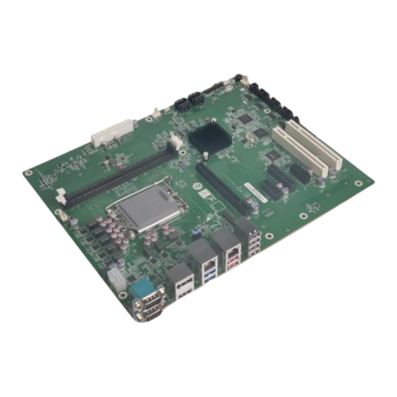
1.1 Introduction Figure 1-1: IMBA-ADL-H610 The IMBA-ADL-H610 is an ATX motherboard. It accepts a Socket LGA1700 Intel® 12/13th Generation Core™ i9/i7/i5/i3, Pentium® or Celeron® processor and supports four 288-pin 3200MHz dual-channel DDR4 SDRAM DIMM modules up to 64 GB. The integrated Intel®... -
Page 16: Features
IMBA-ADL-H610 ATX Motherboard 1.2 Features Some of the IMBA-ADL-H610 motherboard features are listed below: ATX form factor generation LGA1700 Intel® Core™ i9/i7/i5/i3, Pentium® or Celeron® processor supported Intel® H610/H610E chipset Two 288-pin 3200MHz dual-channel DDR4 DIMMs support up to 64 GB Intel®... -
Page 17: Connectors
IMBA-ADL-H610 ATX Motherboard 1.3 Connectors The connectors on the are shown in the figure below. IMBA-ADL-H610 Figure 1-2: Connectors Page 17... -
Page 18: Dimensions
IMBA-ADL-H610 ATX Motherboard 1.4 Dimensions The main dimensions of the IMBA-ADL-H610 are shown in the diagram below. Figure 1-3: IMBA-ADL-H610 Dimensions (mm) Page 18... -
Page 19: Data Flow
IMBA-ADL-H610 ATX Motherboard 1.5 Data Flow Figure 1-4 shows the data flow between the system chipset, the CPU and other components installed on the motherboard. Figure 1-4: Data Flow Diagram Page 19... -
Page 20: Technical Specifications
IMBA-ADL-H610 ATX Motherboard 1.6 Technical Specifications The IMBA-ADL-H610 technical specifications are listed below. 747H Specification/Model IMBA-ADL-H610 Form Factor generation LGA1700 Intel® Core™ i9/i7/i5/i3, CPU Supported Pentium® or Celeron® CPU Intel® H610/H610E Chipset Two 288-pin 2933 MHz dual-channel unbuffered DDR4 Memory SDRAM DIMMs supported (system max. -
Page 21: Table 1-1: Imba-Adl-H610 Specifications
DDR4 memory, EuP mode enabled) Operating 0ºC ~ 60ºC Temperature Storage -30ºC ~ 70ºC Temperature 5% ~ 95% (non-condensing) Operating Humidity Physical Specifications 244 mm x 305 mm Dimensions 1200 g/700 g Weight (GW/NW) Table 1-1: IMBA-ADL-H610 Specifications Page 21... -
Page 22: Packing List
IMBA-ADL-H610 ATX Motherboard Chapter Packing List Page 22... -
Page 23: Anti-Static Precautions
Only handle the edges of the PCB: Don't touch the surface of the motherboard. Hold the motherboard by the edges when handling. 2.2 Unpacking Precautions When the IMBA-ADL-H610 is unpacked, please do the following: Follow the anti-static guidelines above. -
Page 24: Packing List
If any of the components listed in the checklist below are missing, do not proceed with the installation. Contact the IEI reseller or vendor the IMBA-ADL-H610 was purchased from or contact an IEI sales representative directly by sending an email to sales@ieiworld.com. -
Page 25: Optional Items
IMBA-ADL-H610 ATX Motherboard 2.4 Optional Items The following are optional components which may be separately purchased: Item and Part Number Image Dual-port USB cable with bracket (P/N: 19800-003100-100-RS) SATA power cable (P/N: 32102-000100-200-RS) RS-232 cable,230mm,P=2.54 (P/N: 19800-020100-100-RS) Realtek ALC888S 7.1 Channel HD Audio peripheral... -
Page 26: Table 2-2: Optional Items
IMBA-ADL-H610 ATX Motherboard Item and Part Number Image High-performance LGA1155/LGA1156 cooler kit (95W) (P/N: CF-115XE-R10) eDP to eDP DisplayPort converter board (for IEI iDPM connector) (P/N: iDPM-eDP-R10) eDP to LVDS DisplayPort converter board (for IEI iDPM connector) (P/N: iDPM-LVDS-R10) eDP to VBO DisplayPort converter board (for IEI iDPM... -
Page 27: Connectors
IMBA-ADL-H610 ATX Motherboard Chapter Connectors Page 27... -
Page 28: Peripheral Interface Connectors
IMBA-ADL-H610 ATX Motherboard 3.1 Peripheral Interface Connectors This chapter details all the peripheral interface connectors. 3.1.1 IMBA-ADL-H610 Layout The figures below show all the peripheral interface connectors. Figure 3-1: Peripheral Interface Connectors 3.1.2 Peripheral Interface Connectors The table below lists all the connectors on the board. - Page 29 IMBA-ADL-H610 ATX Motherboard Connector Type Label Clear CMOS jumper 4-pin switch J_CMOS1 Flash escriptor security override jumper 3-pin header ME_FLASH1 Audio connector for IEI AC-KIT-888S kit 10-pin header IAUDIO ATX power connector 24-pin connector ATX1 ATX CPU 12V power connector...
-
Page 30: External Interface Panel Connectors
IMBA-ADL-H610 ATX Motherboard Connector Type Label IEI iDPM slot iDPM 3040 slot IDPM PCI slots PCI slot PCI1, PCI2 PCIe x1 slot PCIe x1 slot PCIE2, PCIE4 PCIe x4 slot PCIe x4 slot PCIE3 PCIe x16 slot PCIe x16 slot... -
Page 31: Internal Peripheral Connectors
IMBA-ADL-H610 ATX Motherboard 3.2 Internal Peripheral Connectors The section describes all of the connectors on the IMBA-ADL-H610. 3.2.1 ATX CPU 12V Power Connector CN Label: CPU12V1 CN Type: 8-pin Molex power connector CN Location: See Figure 3-2 The ATX CPU 12V power connector Supply 12V power to the CPU. -
Page 32: At/Atx Power Mode Setting
IMBA-ADL-H610 ATX Motherboard 3.2.2 AT/ATX Power Mode Setting CN Label: J_ATX_AT1 3-pin switch CN Type: CN Location: Figure 3-3 CN Pinouts: See Table 3-3 The AT/ATX power mode selection is made through the AT/ATX power mode switch which is shown in Figure3-6. -
Page 33: Clear Cmos Jumper
IMBA-ADL-H610 ATX Motherboard 3.2.1 Clear CMOS Jumper CN Label: J_CMOS1 4-pin switch CN Type: CN Location: See Figure 3-4 CN Pinouts: See Table 3-4 The J_CMOS1 is used for reset PCH registers in the RTC WELL to their default value. -
Page 34: Flash Descriptor Security Override Jumper
IMBA-ADL-H610 ATX Motherboard 3.2.2 Flash Descriptor Security Override Jumper CN Label: ME_FLASH1 2-pin header, p=1.27 mm CN Type: CN Location: See Figure 3-5 CN Pinouts: See Table 3-5 Figure 3-5: Flash Description Security Override Connector Location Description Description No override (Default) -
Page 35: Atx Power Connector
IMBA-ADL-H610 ATX Motherboard This connector connects to speakers, a microphone and an audio input. Figure 3-6: Audio Connector For IEI AC-KIT-888S Kit Location Description Description HDA_SYNC_R HDA_BCLK_R HDA_SDO_R HDA_PCBEEPC HDA_SDI_0_R HDA_RST_R +12V Table 3-6: Audio Connector For IEI AC-KI-888S Kit Pinouts 3.2.1 ATX Power Connector... -
Page 36: Figure 3-7: Atx Power Connector Location
IMBA-ADL-H610 ATX Motherboard Figure 3-7: ATX Power Connector Location Description Description +3.3V +3.3V +3.3V -12V PS_ON Power good 5VSB +12V +12V +3.3V Table 3-7: ATX Power Connector Pinouts Page 36... -
Page 37: Cpu 12V Power Connector
IMBA-ADL-H610 ATX Motherboard 3.2.2 CPU 12V Power Connector CN Label: CPU12V1 8-pin Molex power connector, p=4.2mm CN Type: CN Location: See Figure 3-8 CN Pinouts: See Table 3-8 This connector provides power to the CPU. Figure 3-8: ATX CPU 12V Power Connector Location PIN NO. -
Page 38: Rtc Battery Connector
IMBA-ADL-H610 ATX Motherboard 3.2.3 RTC Battery Connector CN Label: BAT2 2-pin header, p=1.25 mm CN Type: CN Location: See Figure 3-9 CN Pinouts: See Table 3-9 The RTC battery connector use for connect battery to supply RTC. Figure 3-9: RTC Battery Connector Location... -
Page 39: Chassis Intrusion Connector
IMBA-ADL-H610 ATX Motherboard 3.2.1 Chassis Intrusion Connector CN Label: CHASSIS1 2-pin wafer CN Type: CN Location: Figure 3-10 CN Pinouts: See Table 3-10 The chassis intrusion connector is for a chassis intrusion detection sensor or switch that detects if a chassis component is removed or replaced. -
Page 40: Ddr4 Dimm Sockets
IMBA-ADL-H610 ATX Motherboard 3.2.1 DDR4 DIMM Sockets CN Label: CHA_DIMM1, CHB_DIMM1 288-pin socket CN Type: CN Location: See Figure 3-11 The DIMM slots are for DDR4 DIMM memory modules Figure 3-11: DDR4 DIMM Sockets Location Page 40... -
Page 41: Digital I/O Connector
IMBA-ADL-H610 ATX Motherboard 3.2.1 Digital I/O Connector CN Label: DIO1 14-pin header, p=2.0 mm CN Type: CN Location: See Figure 3-12 CN Pinouts: See Table 3-11 The Digital I/O connector provides programmable input and output for external devices. Figure 3-12: Digital I/O Connector Location... -
Page 42: Ec Debug Connector
IMBA-ADL-H610 ATX Motherboard 3.2.1 EC debug Connector CN Label: DEBUG_1 6-pin wafer, p=1.25 mm CN Type: CN Location: See Figure 3-13 CN Pinouts: See Table 3-12 The DEBUG_SPI1 connector is used for EC debug (with SPI protocol). Figure 3-13: EC Debug Connector Location... -
Page 43: Fan Connector (Cpu)
IMBA-ADL-H610 ATX Motherboard 3.2.1 Fan Connector (CPU) CN Label: CPU_FAN1 4-pin wafer, p=2.54 mm CN Type: CN Location: See Figure 3-14 CN Pinouts: See Table 3-13 The fan connector attaches to a CPU cooling fan. Figure 3-14: CPU Fan Connector Location... -
Page 44: Fan Connectors (System)
IMBA-ADL-H610 ATX Motherboard 3.2.2 Fan Connectors (System) CN Label: SYS_FAN1, SYS_FAN2 4-pin wafer, p=2.54 mm CN Type: CN Location: See Figure 3-15 CN Pinouts: See Table 3-14 Each fan connector attaches to a system cooling fan. The SYS_FAN1&SYS_FAN2 provides smart fan function. -
Page 45: Front Panel Connector
IMBA-ADL-H610 ATX Motherboard 3.2.3 Front Panel Connector CN Label: F_PANEL1 14-pin header, p=2.54 mm CN Type: CN Location: See Figure 3-16 CN Pinouts: See Table 3-15 Figure 3-16: Front Panel Connector Location Description Description PWR_LED+ SPKR+ PWRLED SPKR PWR_LED- PWR_BTN+... -
Page 46: I 2 C Connector
IMBA-ADL-H610 ATX Motherboard 3.2.1 I C Connector CN Label: J_I2C1 4-pin wafer, p=1.25 mm CN Type: CN Location: See Figure 3-17 CN Pinouts: See Table 3-16 The I C connector is used to connect I C-bus devices to the mainboard. -
Page 47: Lan Link Led Connector
IMBA-ADL-H610 ATX Motherboard 3.2.2 LAN Link LED Connector CN Label: JLAN_LED1, JLAN_LED2 2-pin header, p=2.54 mm CN Type: CN Location: Figure 3-18 CN Pinouts: See Table 3-17 The LAN LED connectors are used to connect to the LAN LED indicators on the chassis to indicate users the link activities of the two LAN ports. -
Page 48: Serial Port, Rs-232
IMBA-ADL-H610 ATX Motherboard 3.2.3 Serial Port, RS-232 CN Label: COM3, COM4, COM5, COM6 10-pin header, p=2.00 mm CN Type: CN Location: See Figure 3-19 CN Pinouts: See Table 3-18 Each of these connectors provides RS-232 connections. Figure 3-19: RS-232 Serial Port Connector Location... -
Page 49: Raa229134 Fw Flash Connector
IMBA-ADL-H610 ATX Motherboard 3.2.4 RAA229134 FW Flash Connector CN Label: 2-pin header, p=2.00 mm CN Type: CN Location: See Figure 3-20 CN Pinouts: See Table 3-19 The RAA229134 FW Flash Connector is used for connect RA229134 firmware. Figure 3-20: RAA229134 FW Flash Connector Locations... -
Page 50: Lt86101X Fw Flash Connector
IMBA-ADL-H610 ATX Motherboard 3.2.5 LT86101X FW Flash Connector CN Label: 2-pin header, p=2.00 mm CN Type: CN Location: See Figure 3-21 CN Pinouts: See Table 3-20 The LT86101X connector is used for connect LT86101X firmware. Figure 3-21: LT86101X FW Flash Connector Location... -
Page 51: Sata 6Gb/S Connectors
IMBA-ADL-H610 ATX Motherboard 3.2.1 SATA 6Gb/s Connectors CN Label: SATA1, SATA2, SATA3, SATA4 7-pin SATA connector CN Type: CN Location: See Figure 3-22 CN Pinouts: See Table 3-21 The SATA drive connectors can be connected to SATA drives and support up to 6Gb/s data transfer rate. -
Page 52: Smbus Connector
IMBA-ADL-H610 ATX Motherboard Description SATA_TX+ SATA_TX- SATA_RX- SATA RX+ Table 3-21: SATA 6Gb/s Connector Pinouts 3.2.1 SMBus Connector CN Label: J_SMB1 CN Type: 4-pin wafer, p=1.25 mm CN Location: See Figure 3-23 CN Pinouts: See Table 3-22 The SMBus (System Management Bus) connector provides low-speed system management communications. -
Page 53: Flash Spi Rom Connector
IMBA-ADL-H610 ATX Motherboard Figure 3-23: SMBus Connector Location Description SMB_DATA SMB_CLK Table 3-22: SMBus Connector Pinouts 3.2.1 Flash SPI ROM Connector CN Label: JSPI1 CN Type: 6-pin wafer, p=1.25 mm CN Location: See Figure 3-24 CN Pinouts: See Table 3-23 The Flash SPI ROM connector is used to flash the SPI ROM. -
Page 54: Figure 3-24: Flash Spi Rom Connector Location
IMBA-ADL-H610 ATX Motherboard Figure 3-24: Flash SPI ROM Connector Location Description Description +3.3V SPI_CLK SPI_CS# SPI_SI SPI_SO Table 3-23: Flash SPI ROM Connector Pinouts Page 54... -
Page 55: Flash Ec Rom Connector
IMBA-ADL-H610 ATX Motherboard 3.2.1 Flash EC ROM Connector CN Label: JEC1 8-pin header, p=1.27 mm CN Type: CN Location: See Figure 3-25 CN Pinouts: See Table 3-24 The Flash EC ROM connector is used to flash the EC ROM. Figure 3-25: Flash EC ROM Connector Location... -
Page 56: Internal Usb 2.0 Connector
IMBA-ADL-H610 ATX Motherboard 3.2.1 Internal USB 2.0 Connector CN Label: USB2_CN1 8-pin header, p=1.27 mm CN Type: CN Location: See Figure 3-26 CN Pinouts: See Table 3-25 The Internal USB 2.0 connector connects to USB 2.0 devices. Figure 3-26: Internal USB 2.0 Connector Locations... -
Page 57: Iei Idpm Slot
IMBA-ADL-H610 ATX Motherboard 3.2.2 IEI iDPM Slot CN Label: IDPM CN Type: iDPM 3040 slot CN Location: See Figure 3-27 The IEI iDPM slot is only used for IEI eDP/LVDS/VGA module. Figure 3-27: IEI iDPM Slot Location 3.2.1 PCI Slots... -
Page 58: Pcie X1 Slot
IMBA-ADL-H610 ATX Motherboard Figure 3-28: PCI Slot Locations 3.2.2 PCIe x1 Slot CN Label: PCIE2, PCIE4 PCI Slot CN Type: CN Location: See Figure 3-29 Page 58... -
Page 59: Pcie X4 Slots
IMBA-ADL-H610 ATX Motherboard Figure 3-29: PCIe x1 Slot Locations 3.2.1 PCIe x4 Slots CN Label: PCIE3 CN Type: PCIe x4 slot CN Location: See Figure 3-30 The PCIe x4 expansion card slots are for PCIe x4 expansion cards. Page 59... -
Page 60: Figure 3-30: Pcie X4 Slot Locations
IMBA-ADL-H610 ATX Motherboard Figure 3-30: PCIe x4 Slot Locations Page 60... -
Page 61: Pcie X16 Slots
IMBA-ADL-H610 ATX Motherboard 3.2.1 PCIe x16 Slots CN Label: PCIE1 PCIe x16 slot CN Type: CN Location: See Figure 3-31 The PCIe x16 expansion card slots are for PCIe x16 expansion cards. Figure 3-31: PCIe x8 Slot Locations 3.2.1 Onboard Power Button... -
Page 62: External Peripheral Interface Connector Panel
IMBA-ADL-H610 ATX Motherboard Figure 3-32: Power Button Location 3.3 External Peripheral Interface Connector Panel The figure below shows the external peripheral interface connector (EPIC) panel. The EPIC panel consists of the following: Figure 3-33: External Peripheral Interface Connector Page 62... -
Page 63: External Rs-232/422/485 Combo Connector
IMBA-ADL-H610 ATX Motherboard 3.3.1 External RS-232/422/485 Combo Connector CN Label: COM1, COM2 Dual DB-9 CN Type: CN Location: See Figure 3-33 CN Pinouts: See Table 3-26 The COM1&COM2 connector connects to a serial device that supports RS-232/422/485 communications. RS-232 RS-422... -
Page 64: Figure 3-34: Hdmi Connector
IMBA-ADL-H610 ATX Motherboard Description Description HDMI_DATA2N HDMI_DATA1P HDMI_CLK HDMI_DATA1N HDMI_SDA HDMI_DATA0P HDMI_DATA0N HDMI_HPD HDMI_CLKP Table 3-27: HDMI Connector Pinouts Figure 3-34: HDMI Connector The DP++ connector connects to a display device with DisplayPort interface. Description Description LANE0P LANE3N LANE0N CONFIG_A_1... -
Page 65: External 1Gbe Rj-45 And Dual Usb 3.2 Gen 1 Combo Connector
CN Label: LAN1_USB1 Dual RJ45 CN Type: CN Location: See Figure 3-33 CN Pinouts: See Table 3-29 and Table 3-30 The external 1GbE RJ-45 and dual USB 3.2 Gen 1 connector on the IMBA-ADL-H610. DESCRIPTION DESCRIPTION USB_DATA- USB_DATA- USB_DATA+ USB_DATA+ USB3_RX-... -
Page 66: External 2.5Gbe Rj-45 And Dual Usb 3.2 Gen 2 Combo Connector
CN Label: LAN2_USB2 CN Type: Dual RJ45 CN Location: See Figure 3-33 CN Pinouts: See Table 3-32 and Table 3-33 The external 2.5GbE RJ-45 and dual USB 3.2 Gen 2 connector on the IMBA-ADL-H610. DESCRIPTION DESCRIPTION USB_DATA- USB_DATA- USB_DATA+ USB_DATA+ USB3_RX-... -
Page 67: External Usb 2.0 Connector
CN Type: CN Location: See Figure 3-33 CN Pinouts: See Table 3-35 There are two external USB 2.0 connectors on the IMBA-ADL-H610. The USB 2.0 connector can be connected to a USB 2.0/1.1 device Figure 3-38: USB 2.0 Connector Description Description... -
Page 68: Installation
IMBA-ADL-H610 ATX Motherboard Installation Page 68... -
Page 69: Anti-Static Precautions
This section outlines the installation of peripheral devices to the onboard connectors. 4.2.1 SATA Drive Connection The IMBA-ADL-H610 is shipped with two SATA drive cables. To connect the SATA drives to the connectors, please follow the steps below. Step 1: Locate the connectors. -
Page 70: Figure 4-1: Sata Drive Cable Connection
IMBA-ADL-H610 ATX Motherboard Step 2: Insert the cable connector. Insert the cable connector into the on-board SATA drive connector until it clips into place. See Figure 4-1. Figure 4-1: SATA Drive Cable Connection Step 3: Connect the cable to the SATA disk. Connect the connector on the other end of the cable to the connector at the back of the SATA drive. -
Page 71: Figure 4-2: Sata Power Drive Connection
IMBA-ADL-H610 ATX Motherboard Figure 4-2: SATA Power Drive Connection The SATA power cable can be bought from IEI. See Optional Items in Section 2.4. Page 71... -
Page 72: Installation Considerations
Before and during the installation please DO the following: Read the user manual: The user manual provides a complete description of the IMBA-ADL-H610 installation instructions and configuration options. Wear an electrostatic discharge cuff (ESD): Electronic components are easily damaged by ESD. Wearing an ESD cuff removes ESD from the body and helps prevent ESD damage. -
Page 73: Socket Lga1200 Cpu Installation
IMBA-ADL-H610 ATX Motherboard Remove any of the stickers on the PCB board. These stickers are required for warranty validation. Use the product before verifying all the cables and power connectors are properly connected. Allow screws to come in contact with the PCB circuit, connector pins, or its components. -
Page 74: Figure 4-3: Disengage The Cpu Socket Load Lever
IMBA-ADL-H610 ATX Motherboard Figure 4-3: Disengage The CPU Socket Load Lever Step 2: Open the socket and remove the protective cover. The black protective cover can be removed by pulling up on the tab labeled "Remove". See Figure 4-4. Figure 4-4: Remove Protective Cover Step 3: Inspect the CPU socket. -
Page 75: Figure 4-5: Insert The Socket Lga1200 Cpu
IMBA-ADL-H610 ATX Motherboard Step 4: Orientate the CPU properly. The contact array should be facing the CPU socket. WARNING: DO NOT touch the pins at the bottom of the CPU. When handling the CPU, only hold it on the sides. -
Page 76: Socket Lga1200 Cooling Kit Installation
IMBA-ADL-H610 ATX Motherboard Step 8: Close the CPU socket. Close the load plate and pull the load lever back a little to have the load plate be able to secure to the knob. Engage the load lever by pushing it back to its original position (Figure 4-6). There will be some resistance, but will not require extreme pressure. -
Page 77: Figure 4-7: Cooling Kit Support Bracket
IMBA-ADL-H610 ATX Motherboard WARNING: Do not wipe off (accidentally or otherwise) the pre-sprayed layer of thermal paste on the bottom of the heat sink. The thermal paste between the CPU and the heat sink is important for optimum heat dissipation. -
Page 78: Dimm Installation
Do not overtighten the screws. Step 5: Connect the fan cable. Connect the cooling kit fan cable to the CPU fan connector on the IMBA-ADL-H610. Carefully route the cable and avoid heat generating chips and fan blades.Step 0: 4.6 DIMM Installation... -
Page 79: Module Installation
IMBA-ADL-H610 ATX Motherboard CAUTION: For quad channel configuration, install four identical memory modules that feature the same capacity, timings, voltage, number of ranks and the same brand. 4.7 M.2 Module Installation The IMBA-Q470 provide two ways to install the M.2 expansion card. One is using screw, and the other is using the retainer. -
Page 80: Figure 4-10: Securing The M.2 Module
IMBA-ADL-H610 ATX Motherboard Figure 4-10: Securing the M.2 Module Mode Two: Using the Retainer Step 1: Press the retainer down as shown below. (See Figure 4-11) Figure 4-11: Press the Retainer Page 80... -
Page 81: Figure 4-12: Aligning The M.2 Module With The Retainer
IMBA-ADL-H610 ATX Motherboard Step 2: Line up the notch on the M.2 module with the notch on the slot. Slide the M.2 module into the socket at an angle of about 20º. (See Figure 4-9) Step 3: Align the notch on the end of the M.2 module with the clip of the retainer. (See Figure 4-12) Figure 4-12: Aligning the M.2 Module with the Retainer... -
Page 82: Software Installation
IMBA-ADL-H610 ATX Motherboard 4.8 Software Installation All the drivers for the IMBA-ADL-H610 are available on IEI Resource Download Center (https://download.ieiworld.com). Type IMBA-ADL-H610 and press Enter to find all the relevant software, utilities, and documentation. Figure 4-14: IEI Resource Download Center 4.9 Driver Download... - Page 83 IMBA-ADL-H610 ATX Motherboard Step 3: Click the driver file name on the page and you will be prompted with the following window. You can download the entire ISO file ( ), or click the small arrow to find an individual driver and click the file name to download (...
-
Page 84: Intel ® Amt Setup Procedure
4.10 Intel ® AMT Setup Procedure The IMBA-ADL-H610 is featured with the Intel® Active Management Technology (AMT). To enable the Intel® AMT function, follow the steps below. Step 1: Make sure at least one of the memory sockets is installed with a DDR4 DIMM. -
Page 85: Bios
IMBA-ADL-H610 ATX Motherboard Chapter BIOS Page 85... -
Page 86: Introduction
IMBA-ADL-H610 ATX Motherboard 5.1 Introduction The BIOS is programmed onto the BIOS chip. The BIOS setup program allows changes to certain system settings. This chapter outlines the options that can be changed. NOTE: Some of the BIOS options may vary throughout the life cycle of the product and are subject to change without prior notice. -
Page 87: Using Setup
IMBA-ADL-H610 ATX Motherboard 5.1.2 Using Setup The BIOS Setup menu can be navigated by using a keyboard or a touchscreen. 5.1.2.1 Keyboard Navigation For keyboard navigation, use the navigation keys shown in Table 5-1. Function Up arrow Move to previous item... -
Page 88: Touch Navigation
IMBA-ADL-H610 ATX Motherboard 5.1.2.2 Touch Navigation For touchscreen navigation, use the on-screen navigation keys shown below. On-screen Button Function Previous Values Load the last value you set. Optimized Defaults Load the factory default values in order to achieve the best performance. -
Page 89: Getting Help
IMBA-ADL-H610 ATX Motherboard 5.1.3 Getting Help When F1 is pressed a small help window describing the appropriate keys to use and the possible selections for the highlighted item appears. To exit the Help Window, press the key. 5.1.4 Unable to Reboot after Configuration Changes If the computer cannot boot after changes to the system configuration is made, CMOS defaults. -
Page 90: Main
IMBA-ADL-H610 ATX Motherboard 5.2 Main The Main BIOS menu (BIOS Menu 1 & BIOS Menu 2 & BIOS Menu 3 & BIOS Menu 4) appears when the BIOS Setup program is entered. The Main menu gives an overview of the basic system information. - Page 91 IMBA-ADL-H610 ATX Motherboard BIOS Menu 3: Main (3/4) BIOS Menu 4: Main (4/4) Page 91...
- Page 92 IMBA-ADL-H610 ATX Motherboard BIOS Information The BIOS Information lists a brief summary of the BIOS. The fields in BIOS Information cannot be changed. The items shown in the system overview include: BIOS Vendor: Installed BIOS vendor Core Version: Current BIOS version ...
- Page 93 IMBA-ADL-H610 ATX Motherboard PCH SKU: Displays the PCH SKU Stepping: Displays the PCH Stepping TXT Capability of Platform/PCH: Display the TXT Capability of Platform/PCH Production Type: Display the Production Type ME FW Version: Displays the ME Firmware Version ...
-
Page 94: Advanced
IMBA-ADL-H610 ATX Motherboard 5.3 Advanced Use the Advanced menu (BIOS Menu 5 ) to configure the CPU and peripheral devices through the following sub-menus: WARNING! Setting the wrong values in the sections below may cause the system to malfunction. Make sure that the settings made are compatible with the hardware. -
Page 95: Cpu Configuration
IMBA-ADL-H610 ATX Motherboard 5.3.1 CPU Configuration Use the CPU Configuration menu (BIOS Menu 6 & BIOS Menu 7 & BIOS Menu 8) to view detailed CPU specifications or enable the Intel Virtualization Technology. BIOS Menu 6: CPU Configuration (1/3) Page 95... - Page 96 IMBA-ADL-H610 ATX Motherboard BIOS Menu 7: CPU Configuration (2/3) BIOS Menu 8: CPU Configuration (3/3) Page 96...
- Page 97 IMBA-ADL-H610 ATX Motherboard Intel (VMX) Virtualization Technology [Disabled] Use the Intel (VMX) Virtualization Technology option to enable or disable virtualization on the system. When combined with third party software, Intel® Virtualization technology allows several OSs to run on the same system at the same time.
- Page 98 IMBA-ADL-H610 ATX Motherboard Hyper-Threading [Enabled] Use the Hyper-Threading option to enable or disable the Hyper-Threading Technology. Disabled Disables Hyper-Threading Technology Enabled EFAULT Enables Hyper-Threading Technology Intel(R) SpeedStep(tm) [Enabled] Use the Intel(R) SpeedStep(tm) option to enable or disable the Intel® SpeedStep Technology which allows more than two frequency ranges to be supported.
-
Page 99: Efficient-Core Information
IMBA-ADL-H610 ATX Motherboard Power Limit 1 Time Window Use the Power Limit 1 Time Window option to select the PL1 time duration. The value may vary from 0 to 128. For 0 is the default value. Power Limit 2 Override [Disabled] Power Limit 1 in Milli Watts. - Page 100 IMBA-ADL-H610 ATX Motherboard BIOS Menu 10: Performance-core Information Page 100...
-
Page 101: Trusted Computing
IMBA-ADL-H610 ATX Motherboard 5.3.2 Trusted Computing Use the Trusted Computing menu (BIOS Menu 11) to configure settings related to the Trusted Computing Group (TCG) Trusted Platform Module (TPM). BIOS Menu 11: PCH-FW Configuration Security Device Support [Disable] Use the Security Device Support option to configure support for the TPM. -
Page 102: Iei One Key Recovery
IMBA-ADL-H610 ATX Motherboard 5.3.3 iEi One Key Recovery Use the iEi One Key Recovery menu (BIOS Menu 12) to set or change the configurations for the Auto Recovery Function. BIOS Menu 12: iEi One Key Recovery Auto Recovery Function [disabled] Use the Auto Recovery Function option to enable or disable the watch dog function, when OS crashes It will automatically recover system. - Page 103 IMBA-ADL-H610 ATX Motherboard BIOS Menu 13: RTC Wake Setting RTC Wake Setting [disabled] Use the RTC Wake Setting option to enable or disable the System wake on alarm event Technology, when enabled, system will wake on the date. ...
-
Page 104: F81866 Super Io Configuration
IMBA-ADL-H610 ATX Motherboard 5.3.5 F81866 Super IO Configuration Use the F81866 Super IO Configuration menu (BIOS Menu 14) to set or change the configurations for the parallel ports and serial ports. BIOS Menu 14: F81866 Super IO Configuration Page 104... -
Page 105: Serial Port 1 Configuration
IMBA-ADL-H610 ATX Motherboard 5.3.5.1 Serial Port 1 Configuration Use the Serial Port 1 Configuration menu (BIOS Menu 15) to configure the serial port n. BIOS Menu 15: Serial Port 1 Configuration Menu Serial Port [Enabled] Use the Serial Port option to enable or disable the serial port. -
Page 106: Serial Port 2 Configuration
IMBA-ADL-H610 ATX Motherboard Device Mode [RS232] RS232 The Device Mode is RS232. EFAULT RS422 with The Device Mode is RS422. termination resistor RS485 with The Device Mode is RS485. termination resistor 5.3.5.2 Serial Port 2 Configuration Use the Serial Port 2 Configuration menu (BIOS Menu 16) to configure the serial port n. - Page 107 IMBA-ADL-H610 ATX Motherboard Disable the serial port Disabled Enabled Enable the serial port EFAULT Device Settings Use the Device Settings option to change the serial port IO port address and interrupt address. IO=2F8h; Serial Port I/O port address is 2F8h and the interrupt...
-
Page 108: Serial Port 3 Configuration
IMBA-ADL-H610 ATX Motherboard 5.3.5.3 Serial Port 3 Configuration Use the Serial Port 3 Configuration menu (BIOS Menu 17) to configure the serial port 3. BIOS Menu 17: Serial Port 3 Configuration Menu Serial Port [Enabled] Use the Serial Port option to enable or disable the serial port. -
Page 109: Serial Port 4 Configuration
IMBA-ADL-H610 ATX Motherboard 5.3.5.4 Serial Port 4 Configuration Use the Serial Port 4 Configuration menu (BIOS Menu 18) to configure the serial port 4. BIOS Menu 18: Serial Port 4 Configuration Menu Serial Port [Enabled] Use the Serial Port option to enable or disable the serial port. -
Page 110: Serial Port 5 Configuration
IMBA-ADL-H610 ATX Motherboard 5.3.5.5 Serial Port 5 Configuration Use the Serial Port 5 Configuration menu (BIOS Menu 19) to configure the serial port 5. BIOS Menu 19: Serial Port 5 Configuration Menu Serial Port [Enabled] Use the Serial Port option to enable or disable the serial port. -
Page 111: Serial Port 6 Configuration
IMBA-ADL-H610 ATX Motherboard 5.3.5.6 Serial Port 6 Configuration Use the Serial Port 6 Configuration menu (BIOS Menu 20) to configure the serial port 6. BIOS Menu 20: Serial Port 6 Configuration Menu Serial Port [Enabled] Use the Serial Port option to enable or disable the serial port. -
Page 112: Ec Kb9068 H-W Monitor
IMBA-ADL-H610 ATX Motherboard 5.3.6 EC KB9068 H-W Monitor The EC KB9068 H-W Monitor menu (BIOS Menu 21 & BIOS Menu 22) contains the smart fan mode configuration submenu and shows the state of H/W real-time operating temperature, fan speeds and system voltages. - Page 113 IMBA-ADL-H610 ATX Motherboard BIOS Menu 22: EC KB9068 H-W Monitor (2/2) PC Health Status The following system parameters and values are shown. The system parameters that are monitored are: System Temperatures: CPU Temperature System Temperature Fan Speeds:...
-
Page 114: Smart Fan Mode Configuration
IMBA-ADL-H610 ATX Motherboard 5.3.6.1 Smart Fan Mode Configuration Use the Smart Fan Mode Configuration submenu (BIOS Menu 23 & BIOS Menu 24) to configure the CPU/system fan start/off temperature and control mode. BIOS Menu 23: Smart Fan Mode Configuration (1/2) - Page 115 IMBA-ADL-H610 ATX Motherboard BIOS Menu 24: Smart Fan Mode Configuration (2/2) CPU_FAN1 Smart Fan Control [Auto Mode] Use the CPU_FAN1 Smart Fan Control option to configure the CPU Smart Fan. Manual Mode The fan spins at the speed set in Manual Mode settings.
- Page 116 IMBA-ADL-H610 ATX Motherboard or – key to change the value or enter a decimal number between 1 and 100.. But Fan Speed never less than [Normal Duty] setting. Normal Duty Use the Normal Duty option to set CPU_FAN1 Power On FAN speed and Minimum FAN speed percentage.
-
Page 117: Serial Port Console Redirection
IMBA-ADL-H610 ATX Motherboard SYS_FAN2 Smart Fan Control [Auto Mode] Use the SYS_FAN2 Smart Fan Control option to configure the System Smart Fan. Manual Mode The fan spins at the speed set in Manual Mode settings. Auto Mode The fan adjusts its speed using Auto Mode settings. - Page 118 IMBA-ADL-H610 ATX Motherboard BIOS Menu 25: Serial Port Console Redirection (1/2) BIOS Menu 26: Serial Port Console Redirection (2/2) Page 118...
-
Page 119: Console Redirection Settings
IMBA-ADL-H610 ATX Motherboard Console Redirection [Disabled] Use Console Redirection option to enable or disable the console redirection function. Disabled Disabled the console redirection function EFAULT Enabled Enabled the console redirection function The Console Redirection Settings submenu will be available when the Console Redirection option is enabled. - Page 120 IMBA-ADL-H610 ATX Motherboard The target terminal type is VT100 VT100 VT100+ The target terminal type is VT100+ VT-UTF8 The target terminal type is VT-UTF8 ANSI The target terminal type is ANSI EFAULT Bits per second [115200] Use the Bits per second option to specify the serial port transmission speed.
- Page 121 IMBA-ADL-H610 ATX Motherboard The parity bit is always 1. This option does not allow Mark for error detection. Space The parity bit is always 0. T This option does not allow for error detection. Stop Bits [1] Use the Stop Bits option to specify the number of stop bits used to indicate the end of a serial data packet.
-
Page 122: Chipset
IMBA-ADL-H610 ATX Motherboard 5.4 Chipset Use the Chipset menu (BIOS Menu 28) to access the PCH IO and System Agent (SA) configuration menus. WARNING! Setting the wrong values for the Chipset BIOS selections in the Chipset BIOS menu may cause the system to malfunction. -
Page 123: System Agent (Sa) Configuration
IMBA-ADL-H610 ATX Motherboard 5.4.1 System Agent (SA) Configuration Use the System Agent (SA) Configuration menu (BIOS Menu 29) to configure the System Agent (SA) parameters. BIOS Menu 29: System Agent (SA) Configuration VT-d [Enabled] Use the VT-d option to enable or disable the VT-d capability. -
Page 124: Memory Configuration
IMBA-ADL-H610 ATX Motherboard 5.4.1.1 Memory Configuration Use the Memory Configuration submenu (BIOS Menu 30) to view memory information. BIOS Menu 30: Memory Configuration Page 124... -
Page 125: Graphics Configuration
IMBA-ADL-H610 ATX Motherboard 5.4.1.2 Graphics Configuration Use the Graphics Configuration (BIOS Menu 31) menu to configure the video device connected to the system. BIOS Menu 31: Graphics Configuration Primary Display [Auto] Use the Primary Display option to select the primary graphics controller the system uses. -
Page 126: Lcd Control
IMBA-ADL-H610 ATX Motherboard Internal Graphics [Enabled] Use the Internal Graphics option to configure whether to keep IGFX enabled. If user wants to support dual display by internal graphics and external graphics, this Internal Graphics option should be set to Enabled and the above Primary Display option should be set to IGFX. -
Page 127: Peg Port Configuration
IMBA-ADL-H610 ATX Motherboard BIOS Menu 32: LCD Control LVDS Backlight PWM mode [Invert] Use the LVDS Backlight PWM mode option to change the LVDS Backlight Control PWM Mode Normal or Invert. Normal LVDS Backlight PWM mode normal ... -
Page 128: Pcie Slot Setting
IMBA-ADL-H610 ATX Motherboard BIOS Menu 33: PEG Port Configuration Detect Non-Compliance Device [Enabled] Use the Enable Root Port option to enable or disable the PCI Express (PEG) controller. Disabled Disables the PCI Express (PEG) controller. Enabled Enables the PCI Express (PEG) controller. - Page 129 IMBA-ADL-H610 ATX Motherboard BIOS Menu 34: PCIE1 Configure PEG1 Slot [Enabled] Use the PEG1 Slot BIOS option to set or change PCI express root port. Enabled Enabled the PCI Express Root Port. EFAULT Disabled Disabled the PCI Express Root Port.
-
Page 130: Pch-Io Configuration
IMBA-ADL-H610 ATX Motherboard 5.4.2 PCH-IO Configuration Use the PCH-IO Configuration menu (BIOS Menu 35 & BIOS Menu 36) to configure the PCH parameters. BIOS Menu 35: PCH-IO Configuration (1/2) Page 130... - Page 131 IMBA-ADL-H610 ATX Motherboard BIOS Menu 36: PCH-IO Configuration (2/2) Auto Power Button Function [Disabled(ATX)] Use the Auto Power Button Function BIOS option to show the power mode state. Use the J_ATX_AT1 to switch the AT/ATX power mode. Enabled (AT) The system power mode is AT.
- Page 132 IMBA-ADL-H610 ATX Motherboard USB Power SW2(LAN1_USB1B) [S0/S3/S4/S5 ON] Use the USB Power SW2 BIOS option to configure the USB power source for the corresponding USB connectors (Table 5-3). S3/S4/S5 OFF Sets the USB power configure S3/S4/S5 OFF ...
-
Page 133: Pci Express Configuration
IMBA-ADL-H610 ATX Motherboard Sets the USB power configure S0/S3/S4/S5 ON S0/S3/S4/S5 ON EFAULT BIOS Options Configured USB Ports K/M_USB1 (external USB 2.0 ports) USB Power SW1 LAN1_USB1 (external USB 3.2 Gen 2 ports) LAN2_USB2 (external USB 3.2 Gen 1 ports) USB1 (internal USB 2.0 ports) -
Page 134: Pcie Root Port Setting
IMBA-ADL-H610 ATX Motherboard 5.4.2.1.1 PCIe Root Port Setting Use the PCIE3, PCIE2, PCIE4, IT8893E submenu (BIOS Menu 38) to configure the PCI Root Port Setting. BIOS Menu 38: PCIe Slot Configuration Submenu PCIe Speed [Auto] Use the PCIe Speed option to specify the PCI Express port speed. Configuration options are listed below. - Page 135 IMBA-ADL-H610 ATX Motherboard Detect Non-Compliance Device [Disabled] Use the Detect Non-Compliance Device option to configure whether to detect if a non- compliance PCI Express device is connected to the PCI Express port. Do not detect if a non-compliance PCI Express...
-
Page 136: Sata Configuration
IMBA-ADL-H610 ATX Motherboard 5.4.2.2 SATA Configuration Use the SATA Configuration menu (BIOS Menu 39 & BIOS Menu 40) to change and/or set the configuration of the SATA devices installed in the system. BIOS Menu 39: SATA Configuration (1/2) BIOS Menu 40: SATA Configuration (2/2) - Page 137 IMBA-ADL-H610 ATX Motherboard SATA Mode Selection [AHCI] Use the SATA Mode Selection option to determine how the SATA devices operate. AHCI EFAULT Configures SATA devices as AHCI device. Intel Configures SATA devices to the Intel RST Premium With Premium Intel Optane System Acceleration mode.
-
Page 138: Hd Audio Configuration
IMBA-ADL-H610 ATX Motherboard 5.4.2.3 HD Audio Configuration Use the HD Audio Configuration menu (BIOS Menu 41) to configure the PCH Azalia settings. BIOS Menu 41: HD Audio Configuration HD Audio [Auto] Use the HD Audio option to enable or disable the High Definition Audio controller. -
Page 139: Security
IMBA-ADL-H610 ATX Motherboard 5.5 Security Use the Security menu (BIOS Menu 42 & BIOS Menu 43) to set system and user passwords. BIOS Menu 42: Security (1/2) Page 139... - Page 140 IMBA-ADL-H610 ATX Motherboard BIOS Menu 43: Security (2/2) Administrator Password Use the Administrator Password to set or change an administrator password. User Password Use the User Password to set or change a user password. Page 140...
-
Page 141: Boot
IMBA-ADL-H610 ATX Motherboard 5.6 Boot Use the Boot menu (BIOS Menu 44) to configure system boot options. BIOS Menu 44: Boot 5.6.1 Boot Configuration Quiet Boot [Enabled] Use the Quiet Boot BIOS option to select the screen display when the system boots. -
Page 142: Boot Option Priorities
IMBA-ADL-H610 ATX Motherboard Ignore all PXE Option ROMs Disabled EFAULT Enabled Load PXE Option ROMs. 5.6.2 Boot Option Priorities Use the Boot Option # N to choose the system boots from the peripherals you selected The following Boot Options are listed as an example. -
Page 143: Save & Exit
IMBA-ADL-H610 ATX Motherboard 5.7 Save & Exit Use the Safe & Exit menu (BIOS Menu 45) to load default BIOS values, optimal failsafe values and to save configuration changes. BIOS Menu 45: Save & Exit Save Changes and Reset Use the Save Changes and Reset option to save the changes made to the BIOS options and reset the system. - Page 144 IMBA-ADL-H610 ATX Motherboard Save as User Defaults Use the Save as User Defaults option to save the changes done so far as user defaults. Restore User Defaults Use the Restore User Defaults option to restore the user defaults to all the setup options.
-
Page 145: A Regulatory Compliance
IMBA-ADL-H610 ATX Motherboard Appendix Regulatory Compliance Page 145... - Page 146 IMBA-ADL-H610 ATX Motherboard DECLARATION OF CONFORMITY This equipment has been tested and found to comply with specifications for CE marking. If the user modifies and/or installs other devices in the equipment, the CE conformity declaration may no longer apply. FCC WARNING This equipment complies with Part 15 of the FCC Rules.
-
Page 147: B Product Disposal
IMBA-ADL-H610 ATX Motherboard Appendix Product Disposal Page 147... - Page 148 IMBA-ADL-H610 ATX Motherboard CAUTION: Risk of explosion if battery is replaced by an incorrect type. Only certified engineers should replace the on-board battery. Dispose of used batteries according to instructions and local regulations. Outside the European Union–If you wish to dispose of used electrical and electronic products outside the European Union, please contact your local authority so as to comply with the correct disposal method.
-
Page 149: Cbios Options
IMBA-ADL-H610 ATX Motherboard Appendix BIOS Options Page 149... - Page 150 IMBA-ADL-H610 ATX Motherboard Below is a list of BIOS configuration options in the BIOS chapter. BIOS Information .........................92 Processor Information ......................92 PCH Information ........................92 System Date [xx/xx/xx] ......................93 System Time [xx:xx:xx] .......................93 Intel (VMX) Virtualization Technology [Disabled] .............97 ...
- Page 151 IMBA-ADL-H610 ATX Motherboard Device Settings ........................111 PC Health Status ........................113 CPU_FAN1 Smart Fan Control [Auto Mode] ..............115 Hysteresis Temp.High .......................115 Hysteresis Temp.Low ......................115 Normal Duty ........................116 SYS_FAN1 Smart Fan Control [Auto Mode] ..............116 ...
- Page 152 IMBA-ADL-H610 ATX Motherboard USB Power SW3(USB2_1_C2) [S0/S3/S4/S5 ON] ............132 USB Power SW4(USB2_1_C3) [S0/S3/S4/S5 ON] ............132 USB Power SW5(USB2_CN1_C4) [S0/S3/S4/S5 ON] ............132 USB Power SW7(USB2_CN1_C6) [S0/S3/S4/S5 ON] ............132 PCIe Speed [Auto] ......................134 Detect Non-Compliance Device [Disabled] ..............135 ...
-
Page 153: D Watchdog Timer
IMBA-ADL-H610 ATX Motherboard Appendix Watchdog Timer Page 153... - Page 154 IMBA-ADL-H610 ATX Motherboard NOTE: The following discussion applies to DOS environment. Contact IEI support or visit the IEI website for specific drivers for other operating systems. The Watchdog Timer is provided to ensure that standalone systems can always recover from catastrophic conditions that cause the CPU to crash. This condition may have occurred by external EMIs or a software bug.
- Page 155 IMBA-ADL-H610 ATX Motherboard NOTE: When exiting a program it is necessary to disable the Watchdog Timer, otherwise the system resets. EXAMPLE PROGRAM: ; INITIAL TIMER PERIOD COUNTER W_LOOP: AX, 6F02H ;setting the time-out value BL, 30 ;time-out value is 48 seconds ;...
-
Page 156: E Error Beep Code
IMBA-ADL-H610 ATX Motherboard Appendix Error Beep Code Page 156... -
Page 157: Pei Beep Codes
IMBA-ADL-H610 ATX Motherboard E.1 PEI Beep Codes Number of Beeps Description Memory not Installed Memory was installed twice (InstallPeiMemory routine in PEI Core called twice) Recovery started DXEIPL was not found DXE Core Firmware Volume was not found Recovery failed... -
Page 158: F Hazardous Materials Disclosure
IMBA-ADL-H610 ATX Motherboard Appendix Hazardous Materials Disclosure Page 158... -
Page 159: Rohs Ii Directive (2015/863/Eu)
IMBA-ADL-H610 ATX Motherboard F.1 RoHS II Directive (2015/863/EU) The details provided in this appendix are to ensure that the product is compliant with the RoHS II Directive (2015/863/EU). The table below acknowledges the presences of small quantities of certain substances in the product, and is applicable to RoHS II Directive (2015/863/EU). -
Page 160: China Rhs Ohs
IMBA-ADL-H610 ATX Motherboard F.2 China RoHS 此附件旨在确保本产品符合中国 RoHS 标准。以下表格标示此产品中某有毒物质的含量符 合中国 RoHS 标准规定的限量要求。 本产品上会附有”环境友好使用期限”的标签,此期限是估算这些物质”不会有泄漏或突变”的 年限。本产品可能包含有较短的环境友好使用期限的可替换元件,像是电池或灯管,这些元 件将会单独标示出来。 部件名称 有毒有害物质或元素 壳体 印刷电路板 金属螺帽 电缆组装 风扇组装 电力供应组装 电池 O: 表示该有毒有害物质在该部件所有物质材料中的含量均在 SJ/T11364-2014 與 GB/T26572- 2011 标准规定的限量要求以下。 X: 表示该有毒有害物质至少在该部件的某一均质材料中的含量超出 SJ/T11364-2014 與 GB/T26572-2011 标准规定的限量要求。 Page 160...
Need help?
Do you have a question about the IMBA-ADL-H610 and is the answer not in the manual?
Questions and answers