IEI Technology IMBA-X9654 User Manual
Atc form factor with intel core 2 quad cpu fsb 533/800/1066mhz, vga, dual channel ddr2; lpt; 4xsata ii, 8 x usb 2.0 and 6 x com
Hide thumbs
Also See for IMBA-X9654:
- Quick installation manual (8 pages) ,
- Quick installation manual (9 pages)
Table of Contents
Advertisement
Quick Links
Advertisement
Chapters
Table of Contents

Related Manuals for IEI Technology IMBA-X9654


Summary of Contents for IEI Technology IMBA-X9654
- Page 1 IMBA-X9654 ATX Motherboard IMBA-X9654 ATX Motherboard Page i...
- Page 2 IMBA-X9654 ATX Motherboard Revision Date Version Changes 2009-06-10 1.01 Modified the front panel connector (F_PANEL1) pin locations (Figure 4-10) 2007-06-23 1.00 Initial release Copyright COPYRIGHT NOTICE The information in this document is subject to change without prior notice in order to improve reliability, design and function and does not represent a commitment on the part of the manufacturer.
-
Page 3: Packing List
IMBA-X9654 from or contact an IEI sales representative directly. To contact an IEI sales representative, please send an email to sales@iei.com.tw. The items listed below should all be included in the IMBA-X9654 package. 1 x IMBA-X9654 single board computer 1 x IDE cable... -
Page 4: Table Of Contents
VERVIEW 1.1.1 IMBA-X9654 Features ..................2 1.2 IMBA-X9654 O ..................3 VERVIEW 1.2.1 IMBA-X9654 Overview Photo ................3 1.2.2 IMBA-X9654 Peripheral Connectors and Jumpers ........... 4 1.2.3 Technical Specifications..................5 DETAILED SPECIFICATIONS ................9 2.1 D ......................10 IMENSIONS 2.1.1 Board Dimensions.................... 10 2.1.2 External Interface Panel Dimensions ...............11... - Page 5 IMBA-X9654 ATX Motherboard ® 2.5.4 Intel ICH8DO Low Pin Count (LPC) Interface..........21 ® 2.5.5 Intel ICH8DO PCI Interface................21 2.5.6 Intel® ICH8DO PCIe Ports................21 ® 2.5.7 Intel ICH8DO Low Pin Count (LPC) Interface..........21 ® 2.5.8 Intel ICH8DO Real Time Clock ..............22 ®...
- Page 6 PTIONAL TEMS CONNECTOR PINOUTS..................41 4.1 P ..............42 ERIPHERAL NTERFACE ONNECTORS 4.1.1 IMBA-X9654 Layout ..................42 4.1.2 Peripheral Interface Connectors ..............43 4.1.3 External Interface Panel Connectors............... 44 4.2 I ..............45 NTERNAL ERIPHERAL ONNECTORS 4.2.1 ATX +12V Power Connector ................45 4.2.2 ATX Power Connector ..................
- Page 7 IMBA-X9654 ATX Motherboard 4.3.6 VGA Connector ....................78 4.3.7 Serial Communications Connector ..............79 INSTALLATION ....................81 5.1 A ..................82 STATIC RECAUTIONS 5.2 I ................83 NSTALLATION ONSIDERATIONS 5.2.1 Installation Notices ..................83 5.2.2 Installation Checklist ..................84 5.3 U ......................
- Page 8 IMBA-X9654 ATX Motherboard 5.8.5 Serial Device Connection ................112 5.8.6 USB Connection (Dual Connector) ..............113 5.8.7 VGA Monitor Connection ................114 BIOS SCREENS.....................117 6.1 I ......................118 NTRODUCTION 6.1.1 Starting Setup....................118 6.1.2 Using Setup .....................118 6.1.3 Getting Help....................119 6.1.4 Unable to Reboot After Configuration Changes..........119 6.1.5 BIOS Menu Bar....................119...
- Page 9 IMBA-X9654 ATX Motherboard DRIVER INSTALLATION.................. 179 7.1 A ................180 VAILABLE OFTWARE RIVERS 7.2 D CD A ..................180 RIVER 7.3 C ................182 HIPSET RIVER NSTALLATION 7.4 I ......184 NTEL RAPHICS EDIA CCELERATOR RIVER NSTALLATION 7.5 B LAN D E LAN) I ........
- Page 10 IMBA-X9654 ATX Motherboard E.4.3 Resetting a Disk to Non-RAID............... 239 E.4.4 Exiting the Matrix Storage Manager............. 242 INDEX..........................243 Page x...
- Page 11 IMBA-X9654 ATX Motherboard List of Figures Figure 1-1: IMBA-X9654 Overview [Front View] ............3 Figure 2-1: IMBA-X9654 Dimensions (mm)...............10 Figure 2-2: External Interface Panel Dimensions (mm)...........11 Figure 2-3: Data Flow Block Diagram................12 Figure 2-4: 240-pin DIMM Sockets ................16 Figure 2-5: PCIe x16 Expansion Slot .................17 Figure 2-6: SPI BIOS Chipset ..................20...
- Page 12 Figure 4-20: SPI Flash Connector Pinout Locations ..........70 Figure 4-21: TPM Connector Pinout Locations ............71 Figure 4-22: USB Connector Pinout Locations ............72 Figure 4-23: IMBA-X9654 External Interface Connectors........73 Figure 4-24: PS/2 Pinouts ...................74 Figure 4-25: Parallel Port Connector Pinout Locations ..........75 Figure 4-27: Audio Connector..................76...
- Page 13 IMBA-X9654 ATX Motherboard Figure 5-17: SATA Drive Cable Connection ............105 Figure 5-18: SATA Power Drive Connection ............106 Figure 5-19: Dual USB Cable Connection.............. 107 Figure 5-20: Four Port USB Cable Connection ............. 108 Figure 5-21: Audio Connectors................109 Figure 5-22: LAN Connection...................110...
- Page 14 IMBA-X9654 ATX Motherboard Figure 7-22: Location Browsing Window............... 193 Figure 7-23: Select the Audio CODEC..............194 Figure 7-24: Select the OS..................195 Figure 7-25: Select the OS Version................. 195 Figure 7-26: Locate the Setup Program Icon............196 Figure 7-27: The InstallShield Wizard Starts ............196 Figure 7-28: Preparing Setup Screen ..............
- Page 15 IMBA-X9654 ATX Motherboard List of Tables Table 1-1: Technical Specifications ................7 Table 2-1: Power Consumption..................33 Table 3-1: Package List Contents ................38 Table 3-2: Package List Contents ................40 Table 4-1: Peripheral Interface Connectors ..............44 Table 4-2: Rear Panel Connectors ................45 Table 4-3: ATX Power Connector Pinouts ..............46 Table 4-4: ATX Power Connector Pinouts ..............47...
- Page 16 IMBA-X9654 ATX Motherboard Table 4-25: PS/2 Connector Pinouts................74 Table 4-29: LAN Pinouts .....................77 Table 4-30: RJ-45 Ethernet Connector LEDs ............77 Table 4-31: USB Connector Pinouts ................78 Table 4-32: VGA Connector Pinouts ................79 Table 4-33: COM1 RS-232 Mode Connector Pinouts ..........80 Table 5-1: Jumpers......................96...
- Page 17 IMBA-X9654 ATX Motherboard BIOS Menus Menu 1: Main......................120 Menu 2: Advanced....................122 Menu 3: CPU Configuration..................123 Menu 4: IDE Configuration ..................124 Menu 5: IDE Master and IDE Slave Configuration ..........126 Menu 6: Super IO Configuration ................131 Menu 7: Hardware Health Configuration..............
- Page 18 IMBA-X9654 ATX Motherboard Glossary Hard Disk Drive AC ’97 Audio Codec 97 ACPI Advanced Configuration and Integrated Data Electronics Power Interface Input/Output Advanced Power Management ICH4 I/O Controller Hub 4 ARMD ATAPI Removable Media Device L1 Cache Level 1 Cache...
-
Page 19: Introduction
IMBA-X9654 ATX Motherboard Chapter Introduction Page 1... -
Page 20: Overview
IMBA-X9654 ATX Motherboard 1.1 Overview The IMBA-X9654 ATX form factor motherboard is a LGA775 Intel® Core™2 Quad, Core™2 Duo, Pentium® D, Pentium® 4 or Celeron® D platform with a 533MHz, 800MHz or 1066MHz front side bus (FSB). Up to 8GB of DDR2 SDRAM and up to six SATA II hard disk drives (HDD) are supported. -
Page 21: Imba-X9654 Overview
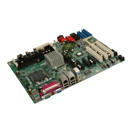
Supports ATX power supplies 1.2 IMBA-X9654 Overview 1.2.1 IMBA-X9654 Overview Photo The IMBA-X9654 has a wide variety of peripheral interface connectors. Figure 1-1 is a labeled photo of the peripheral interface connectors on the IMBA-X9654. Figure 1-1: IMBA-X9654 Overview [Front View]... -
Page 22: Imba-X9654 Peripheral Connectors And Jumpers
1 x SPDIF connector 1 x SPI flash connector 1 x TPM connector 2 x USB 2.0 connectors The IMBA-X9654 has the following external peripheral interface connectors on the board rear panel 3 x Audio jacks 2 x Ethernet connectors... -
Page 23: Technical Specifications
IMBA-X9654 ATX Motherboard Clear CMOS CF card setting Select RS-232/422/485 for COM2 1.2.3 Technical Specifications IMBA-X9654 technical specifications are listed in Table 1-1. See Chapter 2 for details. Specification IMBA-X9654 Form Factor LGA775 Intel® Core™ 2 Quad LGA775 Intel® Core™ 2 Duo LGA775 Intel®... - Page 24 IMBA-X9654 ATX Motherboard One PCIe x16 slot Expansion Options Three PCIe x4 slots Three PCI slots One IrDA by pin header Infrared (IrDA) Dual Intel® Broadcom BCM5787M PCIe GbE chipsets with ASF 2.0 support SuperIO ITE IT8712F CF Type II...
-
Page 25: Table 1-1: Technical Specifications
IMBA-X9654 ATX Motherboard 5%~95% non-condensing Humidity (operating) Dimensions (LxW) 304.80 mm x 243.84 mm Weight (GW/NW) 1350g/750g Table 1-1: Technical Specifications Page 7... -
Page 26: This Page Is Intentionally Left Blank
IMBA-X9654 ATX Motherboard THIS PAGE IS INTENTIONALLY LEFT BLANK Page 8... -
Page 27: Detailed Specifications
IMBA-X9654 ATX Motherboard Chapter Detailed Specifications Page 9... -
Page 28: Dimensions
IMBA-X9654 ATX Motherboard 2.1 Dimensions 2.1.1 Board Dimensions The dimensions of the board are listed below: Length: 304.80mm Width: 243.84mm Figure 2-1: IMBA-X9654 Dimensions (mm) Page 10... -
Page 29: External Interface Panel Dimensions
IMBA-X9654 ATX Motherboard 2.1.2 External Interface Panel Dimensions External peripheral interface connector panel dimensions are shown in Figure 2-2. Figure 2-2: External Interface Panel Dimensions (mm) 2.2 Data Flow Figure 2-3 shows the data flow between the two on-board chipsets and other components installed on the motherboard and described in the following sections of this chapter. -
Page 30: Figure 2-3: Data Flow Block Diagram
IMBA-X9654 ATX Motherboard Figure 2-3: Data Flow Block Diagram Page 12... -
Page 31: Compatible Processors
IMBA-X9654 ATX Motherboard 2.3 Compatible Processors The IMBA-X9654 supports the following LGA775 processors: Intel® Core™2 Quad Intel® Core™2 Duo Intel® Pentium® D Intel® Pentium® 4 Intel® Celeron® D All of the above processors are interfaced with an Intel® Q965 northbridge chipset through the front side bus (FSB). -
Page 32: Intel® Pentium® 4 Features
IMBA-X9654 ATX Motherboard Intel® Advanced Smart Cache Intel® Advanced Digital Media Boost 2.3.3 Intel® Pentium® 4 Features Intel® Pentium® 4 features include: Hyper-Threading Technology Enhanced Intel SpeedStep® Technology Intel® Extended Memory 64 Technology Execute Disable Bit 2.3.4 Intel® Pentium® D Features Intel®... -
Page 33: Intel ® Q965 Northbridge Chipset
® 2.4.2 Intel Q965 Memory Support WARNING: Only DDR2 memory module can be installed on the IMBA-X9654. Do not install DDR memory modules. If a DDR memory module is installed on the IMBA-X9654, the IMBA-X9654 may be irreparably damaged. ®... -
Page 34: Intel Q965 Analog Crt Support
IMBA-X9654 ATX Motherboard Only un-buffered DIMMs supported DDR2 only Maximum supported bandwidth (assuming DDR2 800 MHz): Single-channel: 6.4 GB/s Dual-channel asymmetric mode: 6.4 GB/s Dual-channel interleaved mode: 12.8 GB/s Capacities of 256MB, 512MB, 1GB or 2GB Transfer speeds of 533MHz, 667MHz or 800MHz The memory sockets are shown in Figure 2-4. -
Page 35: Intel ® Q965 Pcie X16
IMBA-X9654 ATX Motherboard Up to 2048x1536 @ 75 Hz refresh Hardware Color Cursor Support DDC2B Compliant Interface ® 2.4.3 Intel Q965 PCIe x16 2.4.3.1 PCIe x16 Bus Overview The Intel® Q965 northbridge has one 16-lane PCIe port that is intended for an external PCIe graphics card. -
Page 36: Intel ® Q965 Direct Media Interface (Dmi)
IMBA-X9654 ATX Motherboard encoding; the port supports a maximum theoretical bandwidth of 40 Gb/s in each direction. Some of the features are listed below. One, 16-lane PCIe port intended for graphics attach, compatible to the PCI Express* Base Specification revision 1.1a. -
Page 37: Intel ® Ich8Do Southbridge Chipset
Integrated SATA host controller with DMA operations and AHCI support interfaced to six SATA connectors on the IMBA-X9654 Supports the eight USB 2.0 devices on the IMBA-X9654 with five UHCI controllers and two EHCI controllers Integrated 10/100/1000 GbE MAC with System Defense Complies with System Management Bus (SMBus) Specification, Version 2.0... -
Page 38: Spi Bios Chipset
2.5.3 Intel High Definition Audio The IMBA-X9654 onboard audio connector can connect to an optional audio kit. The codec on the optional audio kit is connected to the ICH8DO controller through the Intel® High Definition Audio serial link. The DMA engines in the controller move samples of digitally encoded data between system memory and the audio kit codec. -
Page 39: Intel ® Ich8Do Low Pin Count (Lpc) Interface
IMBA-X9654 ATX Motherboard ® 2.5.4 Intel ICH8DO Low Pin Count (LPC) Interface The ICH8DO LPC interface complies with the LPC 1.1 specifications. The LPC bus from the ICH8DO is connected to the following components: BIOS chipset Super I/O chipset ®... -
Page 40: Intel ® Ich8Do Real Time Clock
The two integrated SATA controllers on the ICH8DO southbridge support six SATA II drives on the IMBA-X9654 with independent DMA operations. The SATA controller contains two modes of operation – a legacy mode using I/O space, and an AHCI mode using memory space. -
Page 41: Intel ® Ich8Do Usb Controller
ICH8DO USB Controller Up to eight high-speed, full-speed or low-speed USB devices are supported by the ICH8DO on the IMBA-X9654. High-speed USB 2.0, with data transfers of up to 480MB/s, is enabled with the ICH8DO integrated Enhanced Host Controller Interface (EHCI) compliant host controller. -
Page 42: Intel® Ich8Do Pcie Bus Components
IMBA-X9654 ATX Motherboard Figure 2-8: USB Connector 2.6 Intel® ICH8DO PCIe Bus Components 2.6.1 PCIe Bus Overview The IMBA-X6954 Intel® ICH8DO southbridge PCIe bus is split into two PCIe x1 channels and one PCIe x4 channel. The two PCIe x1 channels are each connected to a Broadcom PCIe GbE controller. -
Page 43: Pcie Gbe Ethernet
IMBA-X9654 ATX Motherboard Figure 2-9: PCIe x4 Expansion The PLX PEX8518 has 16 ports. Four ports are interfaced to four of the PCIe switch ports from the ICH8D0 southbridge. The remaining twelve PCIe ports are interfaced to the three PCIe x4 expansion slots. Some of the features of the PLX PEX8518 are listed below. -
Page 44: Figure 2-10: Broadcom Pci Gbe Controllers
IMBA-X9654 ATX Motherboard Figure 2-10: Broadcom PCI GbE Controllers The Broadcom BCM5787M is a 10/100/1000BASE-T Ethernet LAN controller. The BCM5787M combines a triple-speed IEEE 802.3 compliant Media Access Controller (MAC) with a triple-speed Ethernet transceiver, a PCIe bus interface, and an on-chip buffer memory. -
Page 45: Pci Bus Components
Four PCI expansion slots 2.7.2 ITE 8211 ATA Controller Chipset The 40-pin IDE connectors and the CompactFlash® socket on the IMBA-X9654 are connected to the ATA/ATAPI-6 ITE 8211 ATA controller chipset, which is then connected to the Intel® ICH8DO southbridge chipset through the PCI bus. The controller and connectors are shown in Figure 2-11 below. -
Page 46: Pci Expansion Sockets
IMBA-X9654 ATX Motherboard Four ATA/ATAPI-6 hard disks can be connected to the two IDE connectors or three ATA/ATAPI-6 hard disks and one CF card can be installed. Specifications for the ITE 8211 are listed below. Compatible with ATA/ATAPI-6 specifications Supports ANSI ATA proposal PIO modes 0, 1, 2, 3, and 4 with flow control, DMA modes 0, 1, and 2 and Ultra DMA modes 0, 1, 2, 3, 4, 5 and 6. -
Page 47: Lpc Bus Components
IMBA-X9654 ATX Motherboard Figure 2-12: PCI Expansion Sockets 2.8 LPC Bus Components 2.8.1 LPC Bus Overview The LPC bus is connected to components listed below: Super I/O chipset Serial port chipset Figure 2-13: LPC Bus Components 2.8.2 Super I/O chipset The iTE IT8712F Super I/O chipset is connected to the ICH8DO southbridge through the LPC bus. -
Page 48: Super I/O Lpc Interface
IMBA-X9654 ATX Motherboard Fan Speed Controller Single +5V Power Supply Two 16C550 UARTs for serial port control One IEEE 1284 Parallel Port Keyboard Controller Watchdog Timer Serial IRQ Support Vbat & Vcch Support Single +5V Power Supply Some of the Super I/O features are described in more detail below: 2.8.2.1 Super I/O LPC Interface... -
Page 49: Super I/O Fan Speed Controller
Supports mouse double-click and/or mouse move power on events 2.8.3 Serial Port Chipset The IMBA-X9654 has a Fintek F81216DG chipset onboard enables the addition of four additional UART serial ports (COM3, COM4, COM5 and COM6). UART includes 16-byte send/receive FIFO. The Fintek serial port chipset is interfaced to the southbridge chipset through the LPC bus. -
Page 50: Operating Temperature And Temperature Control
Temperature sensor 3 All three fan speeds are monitored and can be seen in the BIOS as: FAN1 Speed FAN2 Speed FAN3 Speed Eight voltage inputs on the IMBA-X9654 Super I/O Enhanced Hardware Monitor monitor the following volatages: Vcore +3.30V +5.00V +12.0V... -
Page 51: Power Consumption
2.9.3 Power Consumption Table 2-1 shows the power consumption parameters for the IMBA-X9654 running with a 1066MHz FSB 3.73GHz Intel® Pentium® 4 processor with 1GB of 667MHz DDR2 memory. - Page 52 IMBA-X9654 ATX Motherboard THIS PAGE IS INTENTIONALLY LEFT BLANK Page 34...
-
Page 53: Unpacking
IMBA-X9654 ATX Motherboard Chapter Unpacking Page 35... -
Page 54: Anti-Static Precautions
When the IMBA-X9654 is unpacked, please do the following: Follow the anti-static precautions outlined in Section 3.1. Make sure the packing box is facing upwards so the IMBA-X9654 does not fall out of the box. Make sure all the components shown in Section 3.3 are present. -
Page 55: Unpacking Checklist
If some of the components listed in the checklist below are missing, please do not proceed with the installation. Contact the IEI reseller or vendor you purchased the IMBA-X9654 from or contact an IEI sales representative directly. To contact an IEI sales representative, please send an email to sales@iei.com.tw. -
Page 56: Table 3-1: Package List Contents
IMBA-X9654 ATX Motherboard Single RS-232 cable (P/N: 32200-029400-RS) I/O Shielding (P/N: 45002-450903-00-RS) SATA cables (P/N: 32000-062800-RS) SATA power cables (P/N: 32100-088600-RS) Mini jumper Pack Quick Installation Guide Utility CD Table 3-1: Package List Contents Page 38... -
Page 57: Optional Items
IMBA-X9654 ATX Motherboard 3.4 Optional Items 2-port USB cable (w bracket) (P/N:CB-USB02-RS) 4-port USB cable (P/N: CB-USB14-RS) CPU cooling kit (P/N: CF-520-RS) CPU cooling kit (P/N: CF-775A-RS) Dual RS-232/422/485 cable (P/N: 32200-000063-RS) PCIe x16 VGA output SDVO card with dual display support... -
Page 58: Table 3-2: Package List Contents
IMBA-X9654 ATX Motherboard PCIe x16 DVI output SDVO card with dual display support (P/N: SDVO-100DVI-R10) Infineon TPM module (P/N: TPM-IN01-R10) Sinosun TPM module (P/N: TPM-SI01-R10) Winbond TPM module (P/N: TPM-WI01-R10) Table 3-2: Package List Contents Page 40... -
Page 59: Connector Pinouts
IMBA-X9654 ATX Motherboard Chapter Connector Pinouts Page 41... -
Page 60: Peripheral Interface Connectors
IMBA-X9654 ATX Motherboard 4.1 Peripheral Interface Connectors Section 0 shows peripheral interface connector locations. Section 0 lists all the peripheral interface connectors seen in Section 0. 4.1.1 IMBA-X9654 Layout Figure 4-1 shows the on-board peripheral connectors, rear panel peripheral connectors and on-board jumpers. -
Page 61: Peripheral Interface Connectors
IMBA-X9654 ATX Motherboard 4.1.2 Peripheral Interface Connectors Table 4-1 shows a list of the peripheral interface connectors on the IMBA-X9654. Detailed descriptions of these connectors can be found below. Connector Type Label ATX +12V power connector 4-pin ATX CPU12V1 ATX power connector... -
Page 62: External Interface Panel Connectors
8-pin header USB2 Table 4-1: Peripheral Interface Connectors 4.1.3 External Interface Panel Connectors Table 4-2 lists the rear panel connectors on the IMBA-X9654. Detailed descriptions of these connectors can be found in Section 4.3 on page 73 Connector Type Label... -
Page 63: Internal Peripheral Connectors
Internal peripheral connectors are found on the motherboard and are only accessible when the motherboard is outside of the chassis. This section has complete descriptions of all the internal, peripheral connectors on the IMBA-X9654. 4.2.1 ATX +12V Power Connector CN Label:... -
Page 64: Atx Power Connector
IMBA-X9654 ATX Motherboard PIN NO. DESCRIPTION +12V +12V Table 4-3: ATX Power Connector Pinouts 4.2.2 ATX Power Connector CN Label: ATX2 CN Type: 24-pin ATX (2x12) CN Location: See Figure 4-3 CN Pinouts: See Table 4-4 The ATX connector is connected to an external ATX power supply. Power is provided to the system, from the power supply through this connector. -
Page 65: Audio Cd In Connector (4-Pin)
IMBA-X9654 ATX Motherboard PIN NO. DESCRIPTION PIN NO. DESCRIPTION +3.3V +3.3V +3.3V -12V GROUND GROUND PS-ON GROUND GROUND GROUND GROUND GROUND POWER GOOD 5VSB +12V +12V +3.3V Table 4-4: ATX Power Connector Pinouts 4.2.3 Audio CD In Connector (4-pin) CN Label:... -
Page 66: Audio Connector
IMBA-X9654 ATX Motherboard Figure 4-4: Audio CD In Connector Pinouts (4-pin) PIN NO. DESCRIPTION CD Signal (Left) Ground Ground CD Signal (Right) Table 4-5: Audio CD In Connector Pinouts 4.2.4 Audio Connector CN Label: CN Type: 9-pin header (2x5) CN Location:... -
Page 67: Figure 4-5: Audio Connector Location (9-Pin)
IMBA-X9654 ATX Motherboard Figure 4-5: Audio Connector Location (9-pin) PIN NO. DESCRIPTION PIN NO. DESCRIPTION MIC-L MIC-R LINE OUT-R PULL DOWN LINE OUT SENSE LINE OUT-L PULL DOWN Table 4-6: Audio Connector Pinouts Page 49... -
Page 68: Compact Flash Socket
CN Type: CN Location: See Figure 4-6 CN Pinouts: See Table 4-7 A CF Type I or Type II memory card is inserted into the CF socket on the IMBA-X9654. Figure 4-6: CF Card Socket Location PIN NO. DESCRIPTION PIN NO. -
Page 69: Digital Input/Output (Dio) Connector
IMBA-X9654 ATX Motherboard DATA 6 DATA 14 DATA 7 DATA 15 HDC_CS0# HDC_CS1 GROUND IOR# IOW# VCC_COM IRQ15 VCC_COM VCC_COM CSEL HDD_RESET IORDY SDREQ SDACK# HDD_ACTIVE# DATA 0 66DET DATA 1 DATA 8 DATA 2 DATA 9 DATA 10 VCC-IN CHECK2... -
Page 70: Fan Connector (+12V) (Cpu Cooling Fan)
IMBA-X9654 ATX Motherboard Figure 4-7: DIO Connector Connector Locations PIN NO. DESCRIPTION PIN NO. DESCRIPTION Ground Input 0 Output 0 Input 1 Output 1 Input 2 Output 2 Input 3 Output 3 Table 4-8: DIO Connector Connector Pinouts 4.2.7 Fan Connector (+12V) (CPU Cooling Fan) -
Page 71: Fan Connector (+12V) (System Cooling Fans)
IMBA-X9654 ATX Motherboard Figure 4-8: +12V Fan Connector Location PIN NO. DESCRIPTION +12V Rotation Signal Control Table 4-9: +12V Fan Connector Pinouts 4.2.8 Fan Connector (+12V) (System Cooling Fans) CN Label: IO_FAN1, IO_FAN3 CN Type: 3-pin header CN Location: See Figure 4-8... -
Page 72: Front Panel Connector (14-Pin)
IMBA-X9654 ATX Motherboard Figure 4-9: +12V Fan Connector Location PIN NO. DESCRIPTION +12V Fan Speed Detect Table 4-10: +12V Fan Connector Pinouts 4.2.9 Front Panel Connector (14-pin) CN Label: F_PANEL1 14-pin header (2x7) CN Type: CN Location: See Figure 4-10... -
Page 73: Ide Connector (40-Pin)
IMBA-X9654 ATX Motherboard Power LED Speaker Power button Reset HDD LED Figure 4-10: Front Panel Connector Pinout Locations (14-pin) FUNCTION DESCRIPTION FUNCTION DESCRIPTION Power LED+ Buzzer BUZZER- Power PWRBTSW- Button PWRBTSW+ Reset HDD LED IDE_LED+ RESET- IDE_LED- Table 4-11: Front Panel Connector Pinouts (14-pin) 4.2.10 IDE Connector (40-pin) -
Page 74: Figure 4-11: Ide Device Connector Locations
IMBA-X9654 ATX Motherboard CN Location: See Figure 4-11 CN Pinouts: See Table 4-12 Two 40-pin IDE device connectors on the IMBA-X9654 support connectivity to four ATA/33, ATA/66 or ATA/100 hard disk drives. Figure 4-11: IDE Device Connector Locations PIN NO. DESCRIPTION PIN NO. -
Page 75: Infrared Interface Connector (5-Pin)
IMBA-X9654 ATX Motherboard DATA 2 DATA 13 DATA 1 DATA 14 DATA 0 DATA 15 GROUND IDE DRQ GROUND IOW# GROUND IOR# GROUND IDE CHRDY GROUND IDE DACK GROUND–DEFAULT INTERRUPT HDC CS0# HDC CS1# HDD ACTIVE# GROUND Table 4-12: IDE Connector Pinouts 4.2.11 Infrared Interface Connector (5-pin) -
Page 76: Pci Slot
IMBA-X9654 ATX Motherboard Figure 4-12: Infrared Connector Pinout Locations PIN NO. DESCRIPTION IR-RX IR-TX Table 4-13: Infrared Connector Pinouts 4.2.12 PCI Slot CN Label: PCI1 CN Type: PCI Slot CN Location: See Figure 4-13 CN Pinouts: See Table 4-14 The PCI slot enables a PCI expansion module to be connected to the board. -
Page 77: Figure 4-13: Pci Slot Location
IMBA-X9654 ATX Motherboard Figure 4-13: PCI Slot Location PIN NO. DESCRIPTION PIN NO. DESCRIPTION TRST -12V +12V INTA INTC INTB INTD RESERVED3 PRSNT1 Page 59... - Page 78 IMBA-X9654 ATX Motherboard RESERVED1 RESERVED4 PRSNT2 3.3V_AUX RESERVED2 AD30 AD31 +3.3V AD29 AD28 AD26 AD27 AD25 AD24 +3.3V IDSEL C/BE3 +3.3V AD23 AD22 AD20 AD21 AD19 AD18 +3.3V AD16 AD17 +3.3V C/BE2 FRAME IRDY TRDY +3.3V DEVSEL STOP +3.3V LOCK...
-
Page 79: Pci Express X4 Slot
IMBA-X9654 ATX Motherboard SERR +3.3V AD15 C/BE1 +3.3V AD14 AD13 AD11 AD12 AD10 C/BE0 +3.3V +3.3V REQ64 ACK64 Table 4-14: PCI Slot 4.2.13 PCI Express x4 Slot CN Label: PCIE4X_1, PCIE4X_2, PCIE4X_3 CN Type: 64-pin PCIe x4 slots CN Location:... -
Page 80: Figure 4-14: Pcie X4 Connector Locations
IMBA-X9654 ATX Motherboard Figure 4-14: PCIe x4 Connector Locations SIDE A SIDE B NAME NAME NAME NAME +12V +12V +12V +12V +12V SMCLK SMDAT +3.3V +3.3V +3.3V 3.3V RESET WAKE# REFCLK+ REFCLK- HSOp(0) HSIp(0) HSOn(0) HSIn(0) HSOp(1) HSOn(1) HSIp(1) HSIn(1) -
Page 81: Pci Express X16 Slot
IMBA-X9654 ATX Motherboard HSIp(3) HSIn(3) Table 4-15: PCIe x4 Pinouts 4.2.14 PCI Express x16 Slot CN Label: PCIE_1 CN Type: 164-pin PCIe x16 slot CN Location: See Figure 4-25 CN Pinouts: See Table 4-16 (Side A) Table 4-17 (Side B) PCIe x16 expansion devices can be inserted into the PCIe x16 slot. -
Page 82: Figure 4-15: Pcie X16 Connector Location
IMBA-X9654 ATX Motherboard Figure 4-15: PCIe x16 Connector Location NAME NAME NAME NAME Name HSIn(1) HSIp(6) HSIp(11) PRSNT#1 HSIn(6) HSIn(11) +12v +12v HSIp(2) HSIn(2) HSIp(7) HSIp(12) JTAG2 HSIn(7) HSIn(12) JTAG3 JTAG4 HSIp(3) RSVD JTAG5 HSIn(3) HSIp(13) +3.3v HSIp(8) HSIn(13) +3.3v... -
Page 83: Sata Drive Connectors
IMBA-X9654 ATX Motherboard Table 4-16: PCIe x16 Side A Pinouts NAME NAME NAME NAME +12v +12v HSOp(2) RSVD HSOn(2) HSOp(7) HSOp(12) HSOn(7) HSOn(12) SMCLK SMDAT HSOp(3) PRSNT#2 HSOn(3) HSOp(13) +3.3v HSOp(8) HSOn(13) JTAG1 RSVD HSOn(8) 3.3Vaux PRNT#2 WAKE# HSOp(14) RSVD... -
Page 84: Figure 4-16: Sata Drive Connector Locations
IMBA-X9654 ATX Motherboard See Table 4-18 CN Pinouts: The six SATA drive connectors are each connected to a second generation SATA drive. Second generation SATA drives transfer data at speeds as high as 300Mb/s. The SATA drives can be configured in a RAID configuration. -
Page 85: Serial Port Connectors (Rs-232)
IMBA-X9654 ATX Motherboard 4.2.16 Serial Port Connectors (RS-232) CN Label: COM3, COM4, COM5 and COM6 CN Type: 10-pin header (2x5) CN Location: See Figure 4-17 CN Pinouts: See Table 4-19 The four 10-pin serial port connectors provide four additional RS-232 serial communications channels. -
Page 86: Serial Port Connector (Com 2)(Rs-232, Rs-422 Or Rs-485)
IMBA-X9654 ATX Motherboard Data Terminal Ready (DTR) Ring Indicator (RI) Ground (GND) Ground (GND) Table 4-19: RS-232 COM Connector Pinouts 4.2.17 Serial Port Connector (COM 2)(RS-232, RS-422 or RS-485) CN Label: COM2 CN Type: 14-pin header (2x7) CN Location: See Figure 4-18... -
Page 87: Spdif Connector
IMBA-X9654 ATX Motherboard TXD85+ TXD485# RXD85+ RXD485# Table 4-20: RS-232/RS-485 Serial Port Connector Pinouts 4.2.18 SPDIF Connector CN Label: 5-pin header CN Type: CN Location: See Figure 4-19 CN Pinouts: See Table 4-21 Use the SPDIF connector to connect digital audio devices to the system. -
Page 88: Spi Flash Connector
8-pin header CN Type: CN Location: See Figure 4-20 CN Pinouts: See Table 4-22 Use the SPI Flash connector to connect a serial peripheral interface (SPI) flash memory module to the IMBA-X9654. Figure 4-20: SPI Flash Connector Pinout Locations Page 70... -
Page 89: Trusted Platform Module (Tpm) Connector
IMBA-X9654 ATX Motherboard PIN NO. DESCRIPTION PIN NO. DESCRIPTION CLOCK Table 4-22: SPI Flash Connector Pinouts 4.2.20 Trusted Platform Module (TPM) Connector CN Label: TPM1 CN Type: 20-pin header (2x10) CN Location: See Figure 4-21 CN Pinouts: See Table 4-23 The Trusted Platform Module (TPM) connector secures the system on bootup. -
Page 90: Usb Connectors (Internal)
IMBA-X9654 ATX Motherboard LAD0 GND3 SB3V SERIRQ GND1 GLKRUN# LPCPD# LDRQ# Table 4-23: TPM Connector Pinouts 4.2.21 USB Connectors (Internal) CN Label: USB1, USB2 CN Type: 8-pin header (2x4) See Figure 4-22 CN Location: CN Pinouts: See Table 4-24 The 2x4 USB pin connectors each provide connectivity to two USB 1.1 or two USB 2.0 ports. -
Page 91: External Peripheral Interface Connectors
Table 4-24: USB Port Connector Pinouts 4.3 External Peripheral Interface Connectors The external peripheral interface connectors on the back panel are connected to devices externally when the IMBA-X9654 is installed in a chassis. The peripheral connectors on the rear panel are: 1 x Keyboard/mouse connector... -
Page 92: Parallel Port Connector
IMBA-X9654 ATX Motherboard PS/2 connector CN Type: CN Location: See Figure 4-23 CN Pinouts: See Figure 4-24 and Table 4-25 The IMBA-X9654 keyboard and mouse connectors are standard PS/2 connectors. Figure 4-24: PS/2 Pinouts DESCRIPTION DESCRIPTION L_KDAT L_MDAT L_KCLK L_MCLK Table 4-25: PS/2 Connector Pinouts 4.3.2 Parallel Port Connector... -
Page 93: Audio Connectors
IMBA-X9654 ATX Motherboard See Figure 4-25 and Table 4-26 CN Pinouts: These ports are usually connected to a printer. IMBA-X9654 includes one on-board parallel ports accessed through one 25-pin D-type female connector. Figure 4-25: Parallel Port Connector Pinout Locations Description... -
Page 94: Lan Connectors
CN Pinouts: Table 4-27 The IMBA-X9654 is equipped with two built-in RJ-45 Ethernet controllers. The controllers can connect to the LAN through two RJ-45 LAN connectors. There are two LEDs on the connector indicating the status of LAN. The pin assignments are listed in the following... -
Page 95: Usb Connectors
IMBA-X9654 ATX Motherboard DESCRIPTION DESCRIPTION TXA+ TXC- TXA- TXB- TXB+ TXD+ TXC+ TXD- Table 4-27: LAN Pinouts Figure 4-27: RJ-45 Ethernet Connector The RJ-45 Ethernet connector has two status LEDs, one green and one yellow. The green LED indicates activity on the port and the yellow LED indicates the port is linked. See Table 4-28. -
Page 96: Vga Connector
IMBA-X9654 ATX Motherboard Figure 4-28: USB Connector Pinout Locations DESCRIPTION DESCRIPTION USBD0- USBD0- USBD0+ USBD0+ Table 4-29: USB Connector Pinouts 4.3.6 VGA Connector CN Label: CN Type: HD-D-sub 15 Female connector CN Location: See Figure 4-23 (labeled 6) CN Pinouts: See Figure 4-29 and Table 4-30 The standard HD-D-sub 15 female connector connects to a CRT or LCD monitor. -
Page 97: Serial Communications Connector
IMBA-X9654 ATX Motherboard Description Description DDC DAT HSYNC VSYNC DDC CLK Table 4-30: VGA Connector Pinouts 4.3.7 Serial Communications Connector CN Label: COM1 CN Type: D-sub 9 Male connector CN Location: See Figure 4-23 (labeled 7) CN Pinouts: See Figure 4-30 and Table 4-31 The serial connector on the external interface panel provides serial connection in the RS-232 mode. -
Page 98: Table 4-33: Com1 Rs-232 Mode Connector Pinouts
IMBA-X9654 ATX Motherboard REQUEST TO SEND (RTS) CLEAR TO SEND (CTS) RING INDICATOR (RI) Table 4-31: COM1 RS-232 Mode Connector Pinouts Page 80... -
Page 99: Installation
IMBA-X9654 ATX Motherboard Chapter Installation Page 81... -
Page 100: Anti-Static Precautions
Electrostatic discharge (ESD) can cause serious damage to electronic components, including the IMBA-X9654. Dry climates are especially susceptible to ESD. It is therefore critical that whenever the IMBA-X9654, or any other electrical component is handled, the following anti-static precautions are strictly adhered to. -
Page 101: Installation Considerations
IMBA-X9654 is installed. All installation notices pertaining to the installation of the IMBA-X9654 should be strictly adhered to. Failing to adhere to these precautions may lead to severe damage of the IMBA-X9654 and injury to the person installing the motherboard. 5.2.1 Installation Notices... -
Page 102: Installation Checklist
Allow screws to come in contact with the PCB circuit, connector pins, or its components. 5.2.2 Installation Checklist The following checklist is provided to ensure the IMBA-X9654 is properly installed. All the items in the packing list are present The CPU is installed... -
Page 103: Unpacking
When the IMBA-X9654 is unpacked, please do the following: Follow the anti-static precautions outlined in Section 5.1. Make sure the packing box is facing upwards so the IMBA-X9654 does not fall out of the box. Make sure all the components in the checklist shown in Chapter 3 are present. -
Page 104: Cpu, Cpu Cooling Kit And Dimm Installation
Running a CPU without a cooling kit may also result in injury to the user. The CPU, CPU cooling kit and DIMM are the most critical components of the IMBA-X9654. If one of these components is not installed the IMBA-X9654 cannot run. -
Page 105: Figure 5-1: Intel Lga775 Socket
The LGA775 socket is shown in Figure 5-1. Figure 5-1: Intel LGA775 Socket To install a socket LGA775 CPU onto the IMBA-X9654, follow the steps below: WARNING: When handling the CPU, only hold it on the sides. DO NOT touch the pins at the bottom of the CPU. -
Page 106: Figure 5-2: Remove The Cpu Socket Protective Shield
IMBA-X9654 ATX Motherboard Figure 5-2: Remove the CPU Socket Protective Shield Step 2: Open the socket. Disengage the load lever by pressing the lever down and slightly outward to clear the retention tab. Rotate the load lever to a fully open position. -
Page 107: Figure 5-4: Insert The Socket Lga775 Cpu
IMBA-X9654 ATX Motherboard CPU socket. Step 6: Align the CPU pins. Locate pin 1 and the two orientation notches on the CPU. Carefully match the two orientation notches on the CPU with the socket alignment keys. Step 7: Insert the CPU. Gently insert the CPU into the socket. If the CPU pins are properly aligned, the CPU should slide into the CPU socket smoothly. -
Page 108: Lga775 Cooling Kit Installation
WARNING: It is strongly recommended that you DO NOT use the original heat sink and cooler provided by Intel on the IMBA-X9654. IEI’s cooling kits include a support bracket that is combined with the heat sink mounted on the CPU to counterweigh and balance the load on both sides of the PCB. - Page 109 IMBA-X9654 ATX Motherboard WARNING: Do not wipe off (accidentally or otherwise) the pre-sprayed layer of thermal paste on the bottom of the [Fan model#] heat sink. The thermal paste between the CPU and the heat sink is important for optimum heat dissipation.
-
Page 110: Dimm Installation
Step 6: Connect the fan cable. Connect the cooling kit fan cable to the fan connector on the IMBA-X9654. Carefully route the cable and avoid heat generating chips and fan blades.Step 0: 5.4.3 DIMM Installation... -
Page 111: Figure 5-8: Installing A Dimm
IMBA-X9654 ATX Motherboard To install a DIMM into a DIMM socket, please follow the steps below and refer to Figure 5-8. Figure 5-8: Installing a DIMM Step 1: Open the DIMM socket handles. The DIMM socket has two handles that secure the DIMM into the socket. -
Page 112: Cf Card Installation
The IMBA-X9654 can support both CF Type I cards and CF Type II cards. For the complete specifications of the supported CF cards please refer to Chapter 2. To install the a CF card (Type 1 or Type 2) onto the IMBA-X9654, please follow the steps below: Step 1: Locate the CF card socket. -
Page 113: Jumper Settings
IMBA-X9654 ATX Motherboard Figure 5-9: CF Card Installation 5.5 Jumper Settings NOTE: A jumper is a metal bridge that is used to close an electrical circuit. It consists of two metal pins and a small metal clip (often protected by a plastic cover) that slides over the pins to connect them. -
Page 114: Cf Card Setup
IMBA-X9654 ATX Motherboard Before the IMBA-X9654 is installed in the system, the jumpers must be set in accordance with the desired configuration. The jumpers on the IMBA-X9654 are listed in Table 5-1. Description Label Type CF card setup 3-pin header... -
Page 115: Clear Cmos Jumper
Jumper Location: See Figure 5-11 If the IMBA-X9654 fails to boot due to improper BIOS settings, the clear CMOS jumper clears the CMOS data and resets the system BIOS information. To do this, use the jumper cap to close pins 1 and 2 for a few seconds then remove the jumper cap and enable pins 1 and 2 to remain open. -
Page 116: Rs-232/Rs-422/485 Serial Port Select Jumper
IMBA-X9654 ATX Motherboard Jumper Select Description Open Keep CMOS Setup Default Short Clear CMOS Setup Table 5-3: Clear CMOS Jumper Settings The location of the clear CMOS jumper is shown in Figure 5-11 below. Figure 5-11: Clear CMOS Jumper 5.5.3 RS-232/RS-422/485 Serial Port Select Jumper... -
Page 117: Chassis Installation
WARNING: Airflow is critical to the cooling of the CPU and other onboard components. The chassis in which the IMBA-X9654 must have air vents to allow cool air to move into the system and hot air to move out. Page 99... -
Page 118: Internal Peripheral Device Connections
IMBA-X9654 ATX Motherboard The IMBA-X9654 must be installed in a chassis with ventilation holes on the sides allowing airflow to travel through the heat sink surface. In a system with an individual power supply unit, the cooling fan of a power supply can also help generate airflow through the board surface. -
Page 119: Ata Flat Cable Connection
5.7.2 ATA Flat Cable Connection The ATA 66/100 flat cable connects to the IMBA-X9654 to one or two IDE devices. To connect an IDE HDD to the IMBA-X9654 please follow the instructions below. -
Page 120: Dual Rs-232 Cable With Slot Bracket
IMBA-X9654 ATX Motherboard Step 3: Connect the cable to an IDE device. Connect the two connectors on the other side of the cable to one or two IDE devices. Make sure that pin 1 on the cable corresponds to pin 1 on the connectorStep 0: 5.7.3 Dual RS-232 Cable with Slot Bracket... -
Page 121: Single Rs-232 Cable With Slot Bracket
IMBA-X9654 ATX Motherboard 5.7.4 Single RS-232 Cable with Slot Bracket The single RS-232 cable consists of one serial port connectors attached to a serial communications cable that is then attached to a D-sub 9 male connector that is mounted onto a bracket. To install the single RS-232 cable, please follow the steps below. -
Page 122: Dual Rs-232/422/485 Cables
The IMBA-X9654 is shipped with one RS-232/422/485 dual serial port connector cable. The dual serial port connector cable connects the serial port connectors on the cable to the RS-232/422/485 serial port connectors on the IMBA-X9654. Follow the steps below to connect the dual serial port connector cable. -
Page 123: Sata Drive Connection
IMBA-X9654 ATX Motherboard 5.7.6 SATA Drive Connection The IMBA-X9654 is shipped with six SATA drive cables and three SATA drive power cables. To connect the SATA drives to the connectors, please follow the steps below. Step 1: Locate the connectors. The locations of the SATA drive connectors are shown in Chapter 3. -
Page 124: Usb Cable (Dual Port)
IMBA-X9654 ATX Motherboard Figure 5-18: SATA Power Drive Connection 5.7.7 USB Cable (Dual Port) The IMBA-X9654 is shipped with a dual port USB 2.0 cable. To connect the USB cable connector, please follow the steps below. Step 1: Locate the connectors. The locations of the USB connectors are shown in Chapter 3. -
Page 125: Usb Cable (Four Port) (Optional)
5.7.8 USB Cable (Four Port) (Optional) Four port USB 2.0 cables can be separately purchased from IEI. To install a four port USB cable onto the IMBA-X9654, please follow the steps below. Step 1: Locate the connectors. The locations of the USB connectors are shown in Chapter 4. -
Page 126: External Peripheral Interface Connection
1 on the IMBA-X9654 USB connectors. Step 3: Insert the cable connectors.. Once the cable connectors are properly aligned with the USB connectors on the IMBA-X9654, connect the cable connectors to the onboard connectors. See Figure 5-19. Figure 5-20: Four Port USB Cable Connection Step 4: Attach the bracket to the chassis. -
Page 127: Audio Connection
RJ-45 Ethernet cable connectors USB devices To install these devices, connect the corresponding cable connector from the actual device to the corresponding IMBA-X9654 external peripheral interface connector making sure the pins are properly aligned. 5.8.1 Audio Connection Audio signals are interfaced through three phone jack connections. The red phone jack is for Mic In, blue is for Line In and green is for Speaker Out. -
Page 128: Lan Connection
Chapter 4. Step 2: Align the connectors. Align the RJ-45 connector on the LAN cable with one of the RJ-45 connectors on the IMBA-X9654. See Figure 5-22. Figure 5-22: LAN Connection Step 3: Insert the LAN cable RJ-45 connector. Once aligned, gently insert the LAN cable RJ-45 connector into the onboard RJ-45 connector. -
Page 129: Ps/2 Keyboard And Mouse Connection
Step 0: 5.8.4 PS/2 Keyboard and Mouse Connection The IMBA-X9654 has a dual PS/2 connector on the external peripheral interface panel. The dual PS/2 connector is used to connect to a keyboard and mouse to the system. Follow the steps below to connect a keyboard and mouse to the IMBA-X9654. -
Page 130: Serial Device Connection
Step 0: Figure 5-24: PS/2 Keyboard/Mouse Connector 5.8.5 Serial Device Connection The IMBA-X9654 has a single female DB-9 connector on the external peripheral interface panel for a serial device. Follow the steps below to connect a serial device to the IMBA-X9654. -
Page 131: Usb Connection (Dual Connector)
IMBA-X9654 ATX Motherboard Figure 5-25: Serial Device Connector Step 3: Secure the connector. Secure the serial device connector to the external interface by tightening the two retention screws on either side of the connector. Step 0: 5.8.6 USB Connection (Dual Connector) The external USB Series "A"... -
Page 132: Vga Monitor Connection
Figure 5-26: USB Connector 5.8.7 VGA Monitor Connection The IMBA-X9654 has a single female DB-15 connector on the external peripheral interface panel. The DB-15 connector is connected to a CRT or VGA monitor. To connect a monitor to the IMBA-X9654, please follow the instructions below. -
Page 133: Figure 5-27: Vga Connector
IMBA-X9654 ATX Motherboard Figure 5-27: VGA Connector Step 4: Secure the connector. Secure the DB-15 VGA connector from the VGA monitor to the external interface by tightening the two retention screws on either side of the connector. Step 0: Page 115... - Page 134 IMBA-X9654 ATX Motherboard THIS PAGE IS INTENTIONALLY LEFT BLANK Page 116...
-
Page 135: Bios Screens
IMBA-X9654 ATX Motherboard Chapter BIOS Screens Page 117... -
Page 136: Introduction
IMBA-X9654 ATX Motherboard 6.1 Introduction A licensed copy of AMI BIOS is preprogrammed into the ROM BIOS. The BIOS setup program allows users to modify the basic system configuration. This chapter describes how to access the BIOS setup program and the configuration options that may be changed. -
Page 137: Getting Help
IMBA-X9654 ATX Motherboard F1 key General help, only for Status Page Setup Menu and Option Page Setup Menu F2 /F3 key Change color from total 16 colors. F2 to select color forward. F10 key Save all the CMOS changes, only for Main Menu Table 6-1: BIOS Navigation Keys 6.1.3 Getting Help... -
Page 138: Main
IMBA-X9654 ATX Motherboard 6.2 Main The Main BIOS menu (BIOS Menu 1) appears when the BIOS Setup program is entered. The Main menu gives an overview of the basic system information. BIOS Menu 1: Main System Overview The System Overview lists a brief summary of different system components. The fields in System Overview cannot be changed. -
Page 139: Advanced
IMBA-X9654 ATX Motherboard Processor: Displays auto-detected CPU specifications Type: Names the currently installed processor Speed: Lists the processor speed Count: The number of CPUs on the motherboard System Memory: Displays the auto-detected system memory. Size: Lists memory size The System Overview field also has two user configurable fields: System Time [xx:xx:xx] Use the System Time option to set the system time. -
Page 140: Cpu Configuration
IMBA-X9654 ATX Motherboard AHCI Configuration (see Section 6.3.6) APM Configuration (see Section 6.3.7) MPS Configuration (see Section 6.3.8) Remote Access Configuration (see Section 6.3.9) Trusted Computing (see Section 6.3.10) USB Configuration (see Section 6.3.9) BIOS Menu 2: Advanced 6.3.1 CPU Configuration Use the CPU Configuration menu (BIOS Menu 3) to view detailed CPU specifications and configure the CPU. -
Page 141: Ide Configuration
IMBA-X9654 ATX Motherboard BIOS Menu 3: CPU Configuration The CPU Configuration menu (BIOS Menu 3) lists the following CPU details: Manufacturer: Lists the name of the CPU manufacturer Frequency: Lists the CPU processing speed FSB Speed: Lists the FSB speed... -
Page 142: Sata#1 Compatible
IMBA-X9654 ATX Motherboard BIOS Menu 4: IDE Configuration SATA#1 Compatible Use the SATA#1 Compatible BIOS option to select the configuration mode or disable the SATA 1 drive. Disabled SATA 1 drive is disabled Compatible (Default) SATA 1 drive is in compatible mode... -
Page 143: Ide Master, Ide Slave
IMBA-X9654 ATX Motherboard (Default) SATA 1 is configured as an IDE device RAID SATA 1 is configured as an RAID element AHCI SATA 1 is configured as an AHCI device SATA#2 Compatible Use the SATA#2 Compatible BIOS option to select the configuration mode or disable the SATA 2 drive. -
Page 144: Auto-Detected Drive Parameters
IMBA-X9654 ATX Motherboard BIOS Menu 5: IDE Master and IDE Slave Configuration Auto-Detected Drive Parameters The “grayed-out” items in the left frame are IDE disk drive parameters automatically detected from the firmware of the selected IDE disk drive. The drive parameters are listed as follows: Device: Lists the device type (e.g. -
Page 145: Type [Auto]
IMBA-X9654 ATX Motherboard interrupt if block mode is not used. Block mode allows transfers of up to 64 KB per interrupt. PIO Mode: Indicates the PIO mode of the installed device. Async DMA: Indicates the highest Asynchronous DMA Mode that is supported. -
Page 146: Lba/Large Mode [Auto]
IMBA-X9654 ATX Motherboard LBA/Large Mode [Auto] Use the LBA/Large Mode option to disable or enable BIOS to auto detects LBA (Logical Block Addressing). LBA is a method of addressing data on a disk drive. In LBA mode, the maximum drive capacity is 137 GB. -
Page 147: Dma Mode [Auto]
IMBA-X9654 ATX Motherboard PIO mode 0 selected with a maximum transfer rate of 3.3MBps PIO mode 1 selected with a maximum transfer rate of 5.2MBps PIO mode 2 selected with a maximum transfer rate of 8.3MBps PIO mode 3 selected with a maximum transfer rate of 11.1MBps PIO mode 4 selected with a maximum transfer rate of 16.6MBps... -
Page 148: Auto]
IMBA-X9654 ATX Motherboard UDMA1 Ultra DMA mode 0 selected with a maximum data transfer rate of 16.6MBps Ultra DMA mode 1 selected with a maximum data transfer UDMA1 rate of 25MBps UDMA2 Ultra DMA mode 2 selected with a maximum data transfer rate of 33.3MBps... -
Page 149: Super Io Configuration
IMBA-X9654 ATX Motherboard Disabled Prevents the BIOS from using 32-bit data transfers. Enabled Allows BIOS to use 32-bit data transfers on supported EFAULT hard disk drives. 6.3.3 Super IO Configuration Use the Super IO Configuration menu (BIOS Menu 6) to set or change the configurations for the FDD controllers, parallel ports and serial ports. -
Page 150: Parallel Port Mode [Normal]
IMBA-X9654 ATX Motherboard Disabled No I/O port address is assigned to the parallel port (Default) Parallel Port I/O port address is 378 Parallel Port I/O port address is 278 Parallel Port I/O port address is 3BC Parallel Port Mode [Normal] The Parallel Port Mode selection selects the mode the parallel port operates in. -
Page 151: Parallel Port Irq [Irq7]
IMBA-X9654 ATX Motherboard than the Normal mode The parallel port becomes compatible with EPP devices described above Parallel Port IRQ [IRQ7] The Parallel Port Address BIOS option assigns the parallel port interrupt address. The following address options are available. Parallel port interrupt address is IRQ5... -
Page 152: Serial Port2 Mode [Normal]
IMBA-X9654 ATX Motherboard 3E8/IRQ4 Serial Port 2 I/O port address is 3E8 and the interrupt address is IRQ4 Serial Port 2 I/O port address is 2E8 and the interrupt 2E8/IRQ3 address is IRQ3 Serial Port2 Mode [Normal] Use the Serial Port2 Mode option to select the Serial Port2 operational mode. -
Page 153: Serial Port4 Address [2E8]
IMBA-X9654 ATX Motherboard Serial port 3 IRQ address is 10 Serial port 3 IRQ address is 11 EFAULT Serial Port4 Address [2E8] Use the Serial Port4 IRQ option to select the interrupt address for serial port 4. No base address is assigned to serial port 3... -
Page 154: Serial Port5 Irq [11]
IMBA-X9654 ATX Motherboard Serial port 6I/O port address is 2F0 EFAULT Serial port 6 I/O port address is 2E8 Serial Port5 IRQ [11] Use the Serial Port5 IRQ option to select the interrupt address for serial port 5. Serial port 5 IRQ address is 10... -
Page 155: Hardware Health Configuration
IMBA-X9654 ATX Motherboard 6.3.4 Hardware Health Configuration The Hardware Health Configuration menu (BIOS Menu 7) shows the operating temperature, fan speeds and system voltages. BIOS Menu 7: Hardware Health Configuration FAN n Mode Setting [Full On Mode] Use the FAN Mode n Setting option to configure the second fan. -
Page 156: Temperature N Limit Of Off [000]
IMBA-X9654 ATX Motherboard enough. Parameters must be set by the user. PWM Manual mode Pulse width modulation set manually When the FAN Mode n Setting option is in the Automatic Mode, the following parameters can be set. Temperature n Limit of OFF... -
Page 157: Temperature N Limit Of Start [020]
IMBA-X9654 ATX Motherboard Temperature n Limit of Start [020] WARNING: Setting this value too high may cause the fan to start only when the CPU is at a high temperature and therefore cause the system to be damaged. The Temperature n Limit of Start option can only be set if the FAN Mode n Setting option is set to Automatic Mode. - Page 158 IMBA-X9654 ATX Motherboard The Slope PWM n option can only be set if the FAN Mode n Setting option is set to Automatic Mode. Use the Slope PWM n option to select the linear rate at which the PWM mode increases with respect to an increase in temperature. A list of available options is shown below: 0.125 PWM...
-
Page 159: Acpi Configuration
IMBA-X9654 ATX Motherboard 6.3.5 ACPI Configuration The ACPI Configuration menu (BIOS Menu 8) configures the Advanced Configuration and Power Interface (ACPI) and Power Management (APM) options. BIOS Menu 8: ACPI Configuration ACPI Aware O/S [Yes] ACPI Aware O/S can only be configured the OS complies with the ACPI standard. -
Page 160: General Acpi Configuration
IMBA-X9654 ATX Motherboard selection should be enabled if the OS does support ACPI 6.3.5.1 General ACPI Configuration Use the General ACPI Configuration menu (BIOS Menu 9) to select the ACPI state when the system is suspended. BIOS Menu 9: General ACPI Configuration [Advanced\ ACPI Configuration]... -
Page 161: Ahci Configuration
IMBA-X9654 ATX Motherboard the system is running in a low power mode. S3 (STR) System appears off. The CPU has no power; RAM is in slow refresh; the power supply is in a reduced power mode. 6.3.6 AHCI Configuration The AHCI Settings menu reports on the auto-detection of IDE devices connected to the system. -
Page 162: Apm Configuration
IMBA-X9654 ATX Motherboard AHCI Port n [Not Detected] Use the AHCI Port n BIOS option to check what AHCI (Advanced Host Controller Interface) devices are detected by the system. This option displays the status of the auto detection of IDE devices. -
Page 163: Restore On Ac Power Loss [Power Off]
IMBA-X9654 ATX Motherboard On/Off (Default) When the power button is pressed the system is either turned on or off When the power button is pressed the system goes into Suspend suspend mode Restore on AC Power Loss [Power Off] Use the Restore on AC Power Loss BIOS option to specify what state the system returns to if there is a sudden loss of power to the system. -
Page 164: Mps Configuration
IMBA-X9654 ATX Motherboard Enabled Wake event generated by PCI PME controller activity Resume On RTC Alarm [Disabled] Use the Resume On RTC Alarm to specify when the computer is roused from a suspended state. (Default) The real time clock (RTC) cannot generate a wake... -
Page 165: Remote Access Configuration
IMBA-X9654 ATX Motherboard BIOS Menu 12: MPS Configuration MPS Revision [1.1] Use the Multiprocessor Specification (MPS) for OS option to specify the MPS version to be used. MPS version 1.1 is used MPS version 1.4 is used EFAULT 6.3.9 Remote Access Configuration Use the Remote Access Configuration menu (BIOS Menu 13) to configure remote access parameters. -
Page 166: Remote Access [Disabled]
IMBA-X9654 ATX Motherboard BIOS Menu 13: Remote Access Configuration [Advanced] Remote Access [Disabled] Use the Remote Access option to enable or disable access to the remote functionalities of the system. Disabled Remote access is disabled. EFAULT Enabled Remote access configuration options shown below... -
Page 167: Vt-Utf8 Combo Key Support
IMBA-X9654 ATX Motherboard VT-UTF8 Combo Key Support Sredir Memory Display Delay These configuration options are discussed below. Serial Port Number [COM1] Use the Serial Port Number option to select the serial port used for remote access. COM1 System is remotely accessed through COM1... -
Page 168: Flow Control [None]
IMBA-X9654 ATX Motherboard 09600 8,n,1 NOTE: Identical baud rate setting musts be set on the host (a management computer running a terminal software) and the slave Flow Control [None] Use the Flow Control option to report the flow control method for the console redirection application. -
Page 169: Trusted Computing
IMBA-X9654 ATX Motherboard ANSI The target terminal type is ANSI EFAULT VT100 The target terminal type is VT100 VT-UTF8 The target terminal type is VT-UTF8 VT-UTF8 Combo Key Support [Disabled] Use the VT-UFT8 Combo Key Support option to enable additional keys that are not provided by VT100 for the PC 101 keyboard. -
Page 170: Tcg/Tpm Support [Yes]
IMBA-X9654 ATX Motherboard BIOS Menu 14: Trusted Computing TCG/TPM Support [Yes] Use the TCG/TPM Support option to configure support for the TPM. TPM support is disabled. EFAULT TPM support is enabled. TPM Enable/Disable Status [No State] Use the TPM Enable/Disable Status to see if the TPM module has been enabled or disabled. -
Page 171: Usb Configuration
IMBA-X9654 ATX Motherboard 6.3.11 USB Configuration Use the USB Configuration menu (BIOS Menu 15) to read USB configuration information and configure the USB settings. BIOS Menu 15: USB Configuration USB Functions [Enabled] Use the USB Function BIOS option to enable or disable USB function support. -
Page 172: Legacy Usb Support [Enabled]
IMBA-X9654 ATX Motherboard Disabled USB 2.0 controller disabled Enabled USB 2.0 controller enabled EFAULT Legacy USB Support [Enabled] Use the Legacy USB Support BIOS option to enable USB mouse and USB keyboard support. Normally if this option is not enabled, any attached USB mouse or USB keyboard does not become available until a USB compatible operating system is fully booted with all USB drivers loaded. -
Page 173: Usb Mass Storage Device Configuration
IMBA-X9654 ATX Motherboard FullSpeed The controller is capable of operating at 12Mb/s HiSpeed The controller is capable of operating at 480Mb/s EFAULT BIOS EHCI Handoff Use the BIOS EHCI Handoff option for systems running OSes that do not have EHCI hand-off support. -
Page 174: Usb Mass Storage Reset Delay [20 Sec]
IMBA-X9654 ATX Motherboard BIOS Menu 16: USB Mass Storage Device Configuration USB Mass Storage Reset Delay [20 Sec] Use the USB Mass Storage Reset Delay option to set the number of seconds POST waits for the USB mass storage device after the start unit command. -
Page 175: Device
IMBA-X9654 ATX Motherboard 40 Sec POST waits 40 seconds for the USB mass storage device after the start unit command. Device ## The Device## field lists the USB devices that are connected to the system. Emulation Type [Auto] Use the Emulation Type BIOS option to specify the type of emulation BIOS has to provide for the USB device. -
Page 176: Pci/Pnp
IMBA-X9654 ATX Motherboard Hard Disk Allows the USB device to be emulated as hard disk responding to INT13h calls that return DL values of 80h or above. CDROM Assumes the CD-ROM is formatted as bootable media. All the devices that support block sizes greater than 512 bytes can only be booted using this option. -
Page 177: Menu 17: Pci/Pnp Configuration
IMBA-X9654 ATX Motherboard BIOS Menu 17: PCI/PnP Configuration Page 159... -
Page 178: Clear Nvram [No]
IMBA-X9654 ATX Motherboard Clear NVRAM [No] Use the Clear NVRAM option to specify if the NVRAM (Non-Volatile RAM) is cleared when the power is turned off. System does not clear NVRAM during system boot EFAULT System clears NVRAM during system boot Plug &... -
Page 179: Allocate Irq To Pci Vga [Yes]
IMBA-X9654 ATX Motherboard Allocate IRQ to PCI VGA [Yes] Use the Allocate IRQ to PCI VGA option to restrict the system from giving the VGA adapter card an interrupt address. (Default) Assigns an IRQ to a PCI VGA card if card requests IRQ... -
Page 180: Offboard Pci/Isa Ide Card [Auto]
IMBA-X9654 ATX Motherboard OffBoard PCI/ISA IDE Card [Auto] Use the OffBoard PCI/ISA IDE Card BIOS option to select the OffBoard PCI/ISA IDE Card. Auto The location of the Off Board PCI IDE adapter card is EFAULT automatically detected by the AMIBIOS. -
Page 181: Dma Channel# [Available]
IMBA-X9654 ATX Motherboard Available The specified IRQ is available to be used by EFAULT PCI/PnP devices The specified IRQ is reserved for use by Legacy ISA Reserved devices Available IRQ addresses are: IRQ3 IRQ4 IRQ5 IRQ7 IRQ9 IRQ10 IRQ 11... -
Page 182: Boot
IMBA-X9654 ATX Motherboard DM Channel 7 Reserved Memory Size [Disabled] Use the Reserved Memory Size BIOS option to specify the amount of memory that should be reserved for legacy ISA devices. No memory block reserved for legacy ISA devices Disabled... -
Page 183: Boot Settings Configuration
IMBA-X9654 ATX Motherboard 6.5.1 Boot Settings Configuration Use the Boot Settings Configuration menu (BIOS Menu 18) to configure advanced system boot options. BIOS Menu 19: Boot Settings Configuration Quick Boot [Enabled] Use the Quick Boot BIOS option to make the computer speed up the boot process. -
Page 184: Quiet Boot [Disabled]
IMBA-X9654 ATX Motherboard Quiet Boot [Disabled] Use the Quiet Boot BIOS option to select the screen display when the system boots. Disabled Normal POST messages displayed EFAULT Enabled OEM Logo displayed instead of POST messages AddOn ROM Display Mode [Force BIOS] Use the AddOn ROM Display Mode option to allow add-on ROM (read-only memory) messages to be displayed. -
Page 185: Ps/2 Mouse Support [Enabled]
IMBA-X9654 ATX Motherboard PS/2 Mouse Support [Enabled] Use the PS/2 Mouse Support option adjusts PS/2 mouse support capabilities. Disabled PS/2 mouse support is disabled and prevented from using system resources. Enabled Allows the system to use a PS/2 mouse. EFAULT Auto The system auto-adjusts PS/2 mouse support. -
Page 186: Security
IMBA-X9654 ATX Motherboard Enabled Displays “Press DEL to run Setup” message in EFAULT POST Interrupt 19 Capture [Disabled] Use the Interrupt 19 Capture option to allow optional ROMs such as network controllers to trap BIOS interrupt 19. Disabled Does not allow optional ROM to trap interrupt 19... -
Page 187: Change Supervisor Password
IMBA-X9654 ATX Motherboard BIOS Menu 20: Security Change Supervisor Password Use the Change Supervisor Password to set or change a supervisor password. The default for this option is Not Installed. If a supervisor password must be installed, select this field and enter the password. After the password has been added, Install appears next to Change Supervisor Password. -
Page 188: Chipset
IMBA-X9654 ATX Motherboard 6.7 Chipset Use the Chipset menu (BIOS Menu 21) to access the NorthBridge and SouthBridge configuration menus WARNING! Setting the wrong values for the Chipset BIOS selections in the Chipset BIOS menu may cause the system to malfunction. -
Page 189: Northbridge Configuration
IMBA-X9654 ATX Motherboard 6.7.1 NorthBridge Configuration Use the NorthBridge Configuration menu (BIOS Menu 21) to configure the northbridge chipset. BIOS Menu 22:NorthBridge Chipset Configuration DRAM Frequency [Auto] Use the DRAM Frequency option to specify the DRAM frequency or allow the system to automatically detect the DRAM frequency. -
Page 190: Configure Dram Timing By Spd [Enabled]
IMBA-X9654 ATX Motherboard Auto Automatically selects the DRAM frequency EFAULT Configure DRAM Timing by SPD [Enabled] Use the Configure DRAM Timing by SPD option to determine if the system uses the SPD (Serial Presence Detect) EEPROM to configure the DRAM timing. The SPD... -
Page 191: Dram Ras# To Cas# Delay [6 Dram Clocks]
IMBA-X9654 ATX Motherboard 3 nanoseconds DRAM RAS# to CAS# Delay [6 DRAM Clocks] Use the DRAM RAS# to CAS# Delay option to specify the number of clock cycles must elapse between sending a RAS (row address strobe) signal and the CAS (column address strobe) signal. -
Page 192: Memory Hole [Disabled]
IMBA-X9654 ATX Motherboard entirely different memory location is requested. (To be able to change this configuration option the Configure DRAM Timing by SPD configuration option must be set to “Disabled”) The following configuration options are available: 9 DRAM Clocks 10 DRAM Clocks... -
Page 193: Southbridge Configuration
IMBA-X9654 ATX Motherboard Initiate Graphics Adapter [PEG/PCI] Use the Initiate Graphic Adapter option to select the graphics controller used as the primary boot device. Select either an integrated graphics controller (IGD) or a combination of PCI graphics controller, a PCI express (PEG) controller or an IGD. Configuration... -
Page 194: Hda Controller [Enabled]
IMBA-X9654 ATX Motherboard BIOS Menu 23:SouthBridge Chipset Configuration HDA Controller [Enabled] Use the HDA Controller option to enable the high definition audio controller. Disabled HDA controller disabled Enabled (Default) HDA controller enabled ASF Support [Enabled] Use the ASF Support BIOS option to control the system’s ability to connect to a remote management server. -
Page 195: Exit
IMBA-X9654 ATX Motherboard Enabled The Alert Standard Format (ASF) controller is activated EFAULT and can communicate with a remote management server. 6.8 Exit Use the Exit menu (BIOS Menu 24) to load default BIOS values, optimal failsafe values and to save configuration changes. -
Page 196: Save Changes And Exit
IMBA-X9654 ATX Motherboard Save Changes and Exit Use the Save Changes and Exit option to save the changes made to the BIOS options and to exit the BIOS configuration setup program. Discard Changes and Exit Use the Discard Changes and Exit option to exit the BIOS configuration setup program without saving the changes made to the system. -
Page 197: Driver Installation
IMBA-X9654 ATX Motherboard Chapter Driver Installation Page 179... -
Page 198: Available Software Drivers
LAN Driver Installation instructions are given below. 7.2 Driver CD Auto-run All the drivers for the IMBA-X9654 are on the CD that came with the system. To install the drivers, please follow the steps below. Step 1: Insert the CD into a CD drive connected to the system. -
Page 199: Figure 7-1: Introduction Screen
IMBA-X9654 ATX Motherboard Step 2: The driver main menu appears (Figure 7-1). Figure 7-1: Introduction Screen Step 3: Click IMBA-X9654. Step 4: A new screen with a list of available drivers appears (Figure 7-2). Figure 7-2: Available Drivers Step 5: Select the driver to install from the list in Figure 7-2. -
Page 200: Chipset Driver Installation
IMBA-X9654 ATX Motherboard 7.3 Chipset Driver Installation To install the chipset driver, please follow the steps below. Step 1: Select INF from the list in Figure 7-2. Step 2: A new window opens (Figure 7-3). Figure 7-3: Chipset Driver Installation Program Step 3: Double-click the infinst_Autol.exe icon. -
Page 201: Figure 7-5: Chipset Driver Installation License Agreement
IMBA-X9654 ATX Motherboard Step 6: The license agreement in Figure 7-5 appears. Figure 7-5: Chipset Driver Installation License Agreement Step 7: Read the license agreement. To accept the terms and conditions stipulated in the agreement, click Y Step 8: The Readme file in Figure 7-6 appears. -
Page 202: Intel Graphics Media Accelerator Driver Installation
IMBA-X9654 ATX Motherboard installation. Step 10: After the driver installation process is complete, a confirmation screen appears (Figure 7-7). Step 0: Figure 7-7: Chipset Driver Installation Complete Step 1: Click F to complete the driver installation. INISH 7.4 Intel Graphics Media Accelerator Driver Installation To install the chipset driver, please follow the steps below. -
Page 203: Figure 7-8: Select The Operating System
IMBA-X9654 ATX Motherboard Figure 7-8: Select the Operating System Step 4: Double-click the appropriate operating system folder. Step 5: A new window appears (Figure 7-9). Figure 7-9: VGA Driver Step 6: Double-click the installation program icon to continue the installation process. -
Page 204: Figure 7-10: Intel® Graphics Media Accelerator Installshield Wizard
IMBA-X9654 ATX Motherboard Figure 7-10: Intel® Graphics Media Accelerator InstallShield Wizard Step 8: Read the Readme file information and click N to begin extracting files (Figure 7-11). Figure 7-11: InstallShield Wizard Extracting Files Step 9: The Graphics Media Accelerator Driver Welcome screen appears (Figure 7-12). -
Page 205: Figure 7-12: Intel® Graphics Media Accelerator Driver Welcome Screen
IMBA-X9654 ATX Motherboard Figure 7-12: Intel® Graphics Media Accelerator Driver Welcome Screen Step 10: Click N and a license agreement appears (Figure 7-13). Figure 7-13: Intel® Graphics Media Accelerator Driver License Agreement Step 11: Read the license agreement. To accept the terms and conditions stipulated in... -
Page 206: Broadcom Lan Driver (For Gbe Lan) Installation
IMBA-X9654 ATX Motherboard Figure 7-14: Intel® Graphics Media Accelerator Driver Installing Notice Step 12: After the driver installation process is complete, a confirmation screen appears (Figure 7-15). Figure 7-15: Intel® Graphics Media Accelerator Installation Complete Step 13: The confirmation screen offers the option of restarting the computer now or later. -
Page 207: Figure 7-16: Windows Control Panel
IMBA-X9654 ATX Motherboard Figure 7-16: Windows Control Panel Step 2: Double-click the System icon (Figure 7-17). Page 189... -
Page 208: Figure 7-17: System Icon
IMBA-X9654 ATX Motherboard Figure 7-17: System Icon Step 3: Click the Device Manager tab (Figure 7-18). Figure 7-18: Device Manager Tab Step 4: A list of system hardware devices appears (Figure 7-19). Page 190... -
Page 209: Figure 7-19: Device Manager List
IMBA-X9654 ATX Motherboard Figure 7-19: Device Manager List Step 5: Double-click the listed device that has question marks next to it (this means Windows does not recognize the device). Step 6: The Device Driver Wizard appears (Figure 7-20). Page 191... -
Page 210: Figure 7-20: Search For Suitable Driver
IMBA-X9654 ATX Motherboard Figure 7-20: Search for Suitable Driver Step 7: Select “Search for a suitable driver for my device (recommended),” and click to continue. Step 8: Select “Specify a Location” in the Locate Driver Files window (Figure 7-21). Figure 7-21: Locate Driver Files... -
Page 211: Realtek Hd Audio Driver (Alc883) Installation
IMBA-X9654 ATX Motherboard Figure 7-22: Location Browsing Window Step 11: Select the proper OS folder under the “X:\3-LAN\BROADCOM BCM57xx Drivers” directory in the Locate File window, where “X:\” is the system CD drive. Step 12: Click O and the driver is installed.Step 0:... -
Page 212: Figure 7-23: Select The Audio Codec
IMBA-X9654 ATX Motherboard Figure 7-23: Select the Audio CODEC Step 3: Double-click the ALC883 folder. Step 4: Double-click the appropriate operating system folder (Figure 7-24). Page 194... -
Page 213: Figure 7-24: Select The Os
IMBA-X9654 ATX Motherboard Figure 7-24: Select the OS Step 5: Double-click the appropriate operating system version folder (Figure 7-25). Figure 7-25: Select the OS Version Step 6: Double-click the Setup.exe program icon in Figure 7-26. Page 195... -
Page 214: Figure 7-26: Locate The Setup Program Icon
IMBA-X9654 ATX Motherboard Figure 7-26: Locate the Setup Program Icon Step 7: The InstallShield Wizard starts (Figure 7-27). Figure 7-27: The InstallShield Wizard Starts Step 8: The InstallShield Wizard is prepared to guide the user through the rest of the process (Figure 7-28). -
Page 215: Figure 7-28: Preparing Setup Screen
IMBA-X9654 ATX Motherboard Figure 7-28: Preparing Setup Screen Step 9: Once initialized, the InstallShield Wizard welcome screen appears (Figure 7-29). Figure 7-29: InstallShield Wizard Welcome Screen Step 10: Click N to continue the installation. Step 11: InstallShield starts to install the new software as shown in Figure 7-30. -
Page 216: Figure 7-30: Audio Driver Software Configuration
IMBA-X9654 ATX Motherboard Figure 7-30: Audio Driver Software Configuration Step 12: The Installation Wizard updates the system as shown in Figure 7-31. Figure 7-31: Installation Wizard Updates the System Step 13: After the driver installation process is complete, a confirmation screen appears (Figure 7-32). -
Page 217: Sata Raid Driver Installation
IMBA-X9654 ATX Motherboard Figure 7-32: Restart the Computer Step 14: The confirmation screen offers the option of restarting the computer now or later. For the settings to take effect, the computer must be restarted. Click F INISH restart the computer. -
Page 218: Figure 7-33: Sata Raid Driver Installation Program
IMBA-X9654 ATX Motherboard Figure 7-33: SATA RAID Driver Installation Program Step 3: Double-click the INTEL folder. Step 4: Double-click the iata62_cd.exe program icon in Figure 7-34. Page 200... -
Page 219: Figure 7-34: Sata Raid Setup Program Icon
IMBA-X9654 ATX Motherboard Figure 7-34: SATA RAID Setup Program Icon Step 5: Figure 7-35 shows the InstallShield Wizard preparing to guide the user through the rest of the process. Figure 7-35: InstallShield Wizard Setup Screen Step 6: Figure 7-36 shows the Matrix Storage Manager software configuring the installation process. -
Page 220: Figure 7-36: Matrix Storage Manager Setup Screen
IMBA-X9654 ATX Motherboard Figure 7-36: Matrix Storage Manager Setup Screen Step 7: Figure 7-37 shows the Matrix Storage Manager welcome screen. Figure 7-37: Matrix Storage Manager Welcome Screen Step 8: Click N and a warning appears (Figure 7-38). Read the warning carefully and decide whether or not to continue the installation process. -
Page 221: Figure 7-38: Matrix Storage Manager Warning Screen
IMBA-X9654 ATX Motherboard Figure 7-38: Matrix Storage Manager Warning Screen Step 9: Click N and a license agreement appears (Figure 7-39). Figure 7-39: Matrix Storage Manager License Agreement Step 10: Read the license agreement. To accept the terms and conditions stipulated in... -
Page 222: Figure 7-40: Matrix Storage Manager Readme File
IMBA-X9654 ATX Motherboard Figure 7-40: Matrix Storage Manager Readme File Step 11: Read the Readme file information and click N Step 12: After the driver installation process is complete, a confirmation screen appears (Figure 7-41). Figure 7-41: Matrix Storage Manager Setup Complete Step 13: The confirmation screen offers the option of restarting the computer now or later. -
Page 223: Ide Controller Installation
IMBA-X9654 ATX Motherboard For the settings to take effect, the computer must be restarted. Click F INISH restart the computer. Step 0: 7.8 IDE Controller Installation To install the IDE controller, please follow the steps below. Step 1: Open Windows Control Panel (Figure 7-42). -
Page 224: Figure 7-43: Double Click The System Icon
IMBA-X9654 ATX Motherboard Figure 7-43: Double Click the System Icon Step 3: Click the Device Manager tab (Figure 7-44). Page 206... -
Page 225: Figure 7-44: Double Click The Device Manager Tab
IMBA-X9654 ATX Motherboard Figure 7-44: Double Click the Device Manager Tab Step 4: A list of system hardware devices appears (Figure 7-45). Page 207... -
Page 226: Figure 7-45: Device Manager List
IMBA-X9654 ATX Motherboard Figure 7-45: Device Manager List Step 5: Double-click the listed device that has question marks next to it (This means Windows does not recognize the device). Step 6: The Device Driver Wizard appears (Figure 7-46). Page 208... -
Page 227: Figure 7-46: Search For Suitable Driver
IMBA-X9654 ATX Motherboard Figure 7-46: Search for Suitable Driver Step 7: Select “Search for a suitable driver for my device (recommended),” and click to continue. Step 8: The Locate Driver Files window (Figure 7-47) appears. Figure 7-47: Locate Driver Files Step 9: Select “Specify a Location”... -
Page 228: Figure 7-48: Location Browsing Window
IMBA-X9654 ATX Motherboard (Figure 7-48) in the location browsing window, where “X:\” is the system CD drive. Figure 7-48: Location Browsing Window Step 11: Select the iteatapi.inf file, click O and the driver is installed.Step 0: Page 210... -
Page 229: Abios Options
IMBA-X9654 ATX Motherboard Appendix BIOS Options Page 211... - Page 230 IMBA-X9654 ATX Motherboard The following is a list of the BIOS options that are available on this board. System Overview ....................120 System Time [xx:xx:xx] ..................121 System Date [xx/xx/xx] ..................121 SATA#1 Compatible ..................... 124 Configure SATA#1 as [IDE] ................. 124 SATA#2 Compatible .....................
- Page 231 IMBA-X9654 ATX Motherboard FAN n Mode Setting [Full On Mode]..............137 Temperature n Limit of OFF [000]............... 138 Temperature n Limit of Start [020]..............139 Fan n Start PWM [070] ..................139 Slope PWM n [0.5 PWM] ..................139 ACPI Aware O/S [Yes] ..................141 Suspend Mode [S1(POS)]..................
- Page 232 IMBA-X9654 ATX Motherboard TCG/TPM Support [Yes] ..................152 TPM Enable/Disable Status [No State] ............... 152 TPM Owner Status [No State] ................152 USB Functions [Enabled]..................153 USB 2.0 Controller [Enabled]................153 Legacy USB Support [Enabled]................154 Port 64/60 Emulation [Disabled]................. 154 USB2.0 Controller Mode [HiSpeed] ..............
- Page 233 IMBA-X9654 ATX Motherboard Change User Password..................169 DRAM Frequency [Auto] ..................171 Configure DRAM Timing by SPD [Enabled] ............172 DRAM CAS# Latency [5]..................172 DRAM RAS# to CAS# Delay [6 DRAM Clocks]..........173 DRAM RAS# Precharge [3 DRAM Clocks]............173 DRAM RAS# Activate to Precha [15 DRAM Clocks] .........
- Page 234 IMBA-X9654 ATX Motherboard THIS PAGE IS INTENTIONALLY LEFT BLANK Page 216...
-
Page 235: Bdio Interface
IMBA-X9654 ATX Motherboard Appendix DIO Interface Page 217... -
Page 236: Dio Interface Introduction
IMBA-X9654 ATX Motherboard B.1 DIO Interface Introduction The DIO connector on the IMBA-X9654 is interfaced to GIO ports on the iTE Super I/O chipset. The DIO has both 4-bit digital inputs and 4-bit digital outputs. The digital inputs and digital outputs are generally control signals that control the on/off circuit of external devices or TTL devices. -
Page 237: Enable The Dio Output Function
IMBA-X9654 ATX Motherboard B.3.2 Enable the DIO Output Function The BIOS interrupt call INT 15H controls the digital I/O. An assembly program to enable digital I/O output functions is listed below. AX, 6F09H Sets the digital port as output BL, 09H... - Page 238 IMBA-X9654 ATX Motherboard THIS PAGE IS INTENTIONALLY LEFT BLANK Page 220...
-
Page 239: Cwatchdog Timer
IMBA-X9654 ATX Motherboard Appendix Watchdog Timer Page 221... - Page 240 IMBA-X9654 ATX Motherboard NOTE: The following discussion applies to DOS environment. IEI support is contacted or the IEI website visited for specific drivers for more sophisticated operating systems, e.g., Windows and Linux. The Watchdog Timer is provided to ensure that standalone systems can always recover from catastrophic conditions that cause the CPU to crash.
- Page 241 IMBA-X9654 ATX Motherboard NOTE: When exiting a program it is necessary to disable the Watchdog Timer, otherwise the system resets. Example program: ; INITIAL TIMER PERIOD COUNTER W_LOOP: AX, 6F02H ;setting the time-out value BL, 30 ;time-out value is 48 seconds ;...
- Page 242 IMBA-X9654 ATX Motherboard THIS PAGE IS INTENTIONALLY LEFT BLANK Page 224...
-
Page 243: Daddress Mapping
IMBA-X9654 ATX Motherboard Appendix Address Mapping Page 225... -
Page 244: Address Map
IMBA-X9654 ATX Motherboard D.1 Address Map I/O address Range Description 000-01F DMA Controller 020-021 Interrupt Controller 040-043 System time 060-06F Keyboard Controller 070-07F System CMOS/Real time Clock 080-09F DMA Controller 0A0-0A1 Interrupt Controller 0C0-0DF DMA Controller 0F0-0FF Numeric data processor... -
Page 245: Irq Mapping Table
IMBA-X9654 ATX Motherboard D.3 IRQ Mapping Table IRQ0 System Timer IRQ8 RTC clock IRQ1 Keyboard IRQ9 ACPI IRQ2 Available IRQ10 IRQ3 COM2 IRQ11 LAN/USB2.0/SATA IRQ4 COM1 IRQ12 PS/2 mouse IRQ5 SMBus Controller IRQ13 IRQ6 IRQ14 Primary IDE IRQ7 Available IRQ15... - Page 246 IMBA-X9654 ATX Motherboard THIS PAGE IS INTENTIONALLY LEFT BLANK Page 228...
-
Page 247: Intel® Matrix Storage Manager
IMBA-X9654 ATX Motherboard Appendix Intel® Matrix Storage Manager Page 229... -
Page 248: Introduction
IMBA-X9654 ATX Motherboard E.1 Introduction The Intel® ICH7R chipset can provide data protection for serial ATA (SATA) disks via the Intel® Matrix Storage Manager using one of three fault-tolerant RAID levels: RAID 1, 5 or 10. When using two hard drives, matrix RAID allows RAID 0 and RAID 1 functions to be combined, where critical files can be stored on RAID 1, and RAID 0 can be used for non-critical items such as software. -
Page 249: Features And Benefits
IMBA-X9654 ATX Motherboard CAUTION! Do not accidentally disconnect the SATA drive cables. Carefully route the cables within the chassis to avoid system down time. E.2 Features and Benefits Supports RAID levels 0, 1, 5 and 10 Supports connectivity to two or more disk drives... -
Page 250: Raid Configuration
IMBA-X9654 ATX Motherboard Step 3: Save and Exit BIOS. After the SATA support option is enabled, save and exit the BIOS. Step 4: Reboot the system. Reboot the system after saving and exiting the BIOS. Step 5: Press Ctrl+I. During the system boot process, press Ctrl+I when prompted to enter the RAID configuration software. - Page 251 IMBA-X9654 ATX Motherboard Step 1: Select “Create RAID Volume.” Use the arrow keys to highlight Create RAID Volume and press E . See Figure E-1. NTER Figure E-1: Matrix Storage Manager Main Menu Step 2: Name the RAID volume. Enter a name for the RAID volume, or press E NTER accept the default volume name.
- Page 252 IMBA-X9654 ATX Motherboard Step 3: Choose the RAID level. Select a RAID level from the list. RAID levels include RAID 0, 1, 5 and 10. See Figure E-3. NOTE: RAID 0 and RAID1 levels require a minimum of two hard drives.
- Page 253 IMBA-X9654 ATX Motherboard Step 4: Select the Stripe Size. Select a stripe size from the list. See Figure E-4. Figure E-4: Select the Stripe Size Step 5: Enter the Volume Capacity. Enter the volume capacity, or press E NTER accept the default capacity. See Figure E-5.
- Page 254 IMBA-X9654 ATX Motherboard Step 6: Create the RAID Volume. Press E to create the RAID volume as specified. NTER See Figure E-6. Figure E-6: Create the RAID Volume Step 7: Create RAID Volume Verification. After reading the warning, press Y to create the RAID volume as specified, or N to return to the Create RAID Volume menu.
-
Page 255: Deleting A Raid Volume
IMBA-X9654 ATX Motherboard E.4.2 Deleting a RAID Volume WARNING! All data stored on the member drives of a RAID volume are destroyed during the RAID deletion process. Make sure any data to be saved has been moved or backed up before deleting a RAID volume. - Page 256 IMBA-X9654 ATX Motherboard Step 2: Select RAID Volume to be Deleted. Use the arrow keys to highlight the RAID volume to be deleted and press E . See Figure E-9. NTER Figure E-9: Select RAID Volume to be Deleted Step 3: Delete Volume Verification.
-
Page 257: E.4.3 Resetting A Disk To Non-Raid
IMBA-X9654 ATX Motherboard Step 4: Non-RAID Disks. After deleting the RAID volume, the disks belonging to the volume will be shown as non-RAID disks. See Figure E-11. Step 0: Figure E-11: Non-RAID Disks E.4.3 Resetting a Disk to Non-RAID WARNING! All data stored on the disk drive of a RAID volume is destroyed when resetting it to non-RAID. - Page 258 IMBA-X9654 ATX Motherboard Step 1: Select “Reset Disk to Non-RAID.” Use the arrow keys to highlight Reset Disk to Non-RAID and press E . See Figure E-12. NTER Figure E-12: Reset Disk to Non-RAID Menu Step 2: Select Disks to Reset. Use the arrow keys to scroll through the disk drives and press S to select which drives are to be reset as non-RAID.
- Page 259 IMBA-X9654 ATX Motherboard Step 3: Reset Disk Verification. After reading the warning, press Y to reset the selected disks as non-RAID, or N to return to the Reset RAID Data menu. See Figure E-14. Figure E-14: Reset Disk Verification Step 4: Disk Drive and RAID Volume Status.
-
Page 260: E.4.4 Exiting The Matrix Storage Manager
IMBA-X9654 ATX Motherboard E.4.4 Exiting the Matrix Storage Manager Step 1: Select “Exit.” Use the arrow keys to highlight Exit and press E NTER See Figure E-16. Figure E-16: Exit Menu Step 2: Exit Verification. Press Y to exit the Matrix Storage Manager, or N to return to the Main menu. -
Page 261: Index
IMBA-X9654 ATX Motherboard Index Page 243... - Page 262 IMBA-X9654 ATX Motherboard ATA 66/100 flat cable ..... 37 dual port USB ....... 106 dual RS-232 cable ......102 ACPI......... 141, 142 four port USB........ 107 Advanced Power Management ..177 four serial port....... 104 airflow ..........99 SATA drive......38, 105 anti-static precautions ....
- Page 263 IMBA-X9654 ATX Motherboard ATX power........46 board ..........10 audio CD in ........47 external peripheral interface connector COM 2 serial port ....67, 68, 69 panel..........11 CompactFlash ......... 50 DIMM ..........92 fan ..........52, 53 installation........92 front panel ........54 specifcations........
- Page 264 IMBA-X9654 ATX Motherboard fan speed controller......31 FDD........... 131 jumper ........... 95, 96 four port USB cable ......107 CF card setup ........96 four serial port cable ......104 clear CMOS ........97 front panel connector ...... 4, 54 jumper configuration.......
- Page 265 IMBA-X9654 ATX Motherboard peripheral connectors ......45 COM 2 location and pinouts ... 68 peripheral device cables....100 RS-485 .......... 68, 69 power button ........55 COM 2 location and pinouts ... 68 Power Button Mode ......144 power supply........45 AT power supply ......
- Page 266 IMBA-X9654 ATX Motherboard trusted platform module...... 71 USB 2.0........... 72 trusted platform module (TPM) USB 1.1..........72 connector......... 71 USB 2.0........72, 153 location and pinouts ......71 USB 2.0 connector ........ 4 USB cable dual port ........106 four port ........107 unpacking........
Need help?
Do you have a question about the IMBA-X9654 and is the answer not in the manual?
Questions and answers