Table of Contents
Advertisement
Quick Links
IMB-H612 Mic ro -ATX Mo th e rb o a rd
IEI Te c h n o lo g y Co rp .
MODEL:
IMB-H612
Mic ro ATX Mo th e rb o a rd s u p p o rts LGA1155 In te l® Co re ™
i7/i5/i3/P e n tiu m ®/Ce le ro n ® CP U p e r In te l® H61, DDR3, Du a l VGA,
d u a l Re a lte k P CIe Gb E, US B 2.0, COM, S ATA 3Gb /s ,
Re v. 1.01 –Ma rc h 31, 2012
HD Au d io a n d Ro HS
Us e r Ma n u a l
P a g e i
Advertisement
Table of Contents

Related Manuals for IEI Technology IMB-H612


Summary of Contents for IEI Technology IMB-H612
- Page 1 IMB-H612 Mic ro -ATX Mo th e rb o a rd IEI Te c h n o lo g y Co rp . MODEL: IMB-H612 Mic ro ATX Mo th e rb o a rd s u p p o rts LGA1155 In te l® Co re ™...
- Page 2 IMB-H612 Mic ro -ATX Mo th e rb o a rd Re vis io n Date Version Changes March 31, 2012 1.01 Update Section 2.4: Optional Items November 30, 2011 1.00 Initial release P a g e ii...
- Page 3 IMB-H612 Mic ro -ATX Mo th e rb o a rd Co p yrig h t COP YRIGHT NOTICE The information in this document is subject to change without prior notice in order to improve reliability, design and function and does not represent a commitment on the part of the manufacturer.
-
Page 4: Table Of Contents
IMB-H612 Mic ro -ATX Mo th e rb o a rd Ta b le o f Co n te n ts 1 INTRODUCTION ......................1 1.1 I ......................2 NTRODUCTION 1.2 M ....................2 ODEL ARIATIONS 1.3 B ........................3 ENEFITS 1.4 F... - Page 5 IMB-H612 Mic ro -ATX Mo th e rb o a rd 3.2.10 PCI Slot ......................26 3.2.11 PCIe x1 Slots ....................27 3.2.12 SATA 3Gb/s Drive Connectors ............... 28 3.2.13 Serial Port Connector, RS-422/485 ..............29 3.2.14 Serial Port Connectors, RS-232 ..............30 3.2.15 SMBus Connector ..................
- Page 6 IMB-H612 Mic ro -ATX Mo th e rb o a rd 4.6.5 USB Connection ....................62 4.6.6 VGA Monitor Connection ................63 5 BIOS ..........................65 5.1 I ......................66 NTRODUCTION 5.1.1 Starting Setup ....................66 5.1.2 Using Setup ...................... 66 5.1.3 Getting Help .....................
- Page 7 IMB-H612 Mic ro -ATX Mo th e rb o a rd 5.4.4 ME Subsystem ....................105 5.5 B ........................106 5.6 S ....................... 107 ECURITY 5.7 S & E ......................108 6 SOFTWARE DRIVERS ..................... 110 6.1 A ................111...
- Page 8 IMB-H612 Mic ro -ATX Mo th e rb o a rd B.6.4 Start the DHCP, TFTP and HTTP ..............162 B.6.5 Create Shared Directory ................162 B.6.6 Setup a Client System for Auto Recovery ............164 B.7 O .................... 166...
- Page 9 IMB-H612 Mic ro -ATX Mo th e rb o a rd Lis t o f Fig u re s Figure 1-1: IMB-H612 ........................2 Figure 1-2: Connectors ........................4 Figure 1-3: IMB-H612 Dimensions (mm) ..................5 Figure 1-4: Data Flow Diagram ...................... 6 Figure 3-1: Connectors and Jumpers ..................15...
- Page 10 IMB-H612 Mic ro -ATX Mo th e rb o a rd Figure 4-2: Remove Protective Cover ..................48 Figure 4-3: Insert the Socket LGA1155 CPU ................49 Figure 4-4: Close the Socket LGA1155 ..................50 Figure 4-5: Cooling Kits (CF-1156A-RS, CF-1156B-RS, CF-1156C-RS) ........50 Figure 4-6: Cooling Kit Support Bracket ..................51...
- Page 11 IMB-H612 Mic ro -ATX Mo th e rb o a rd Figure 6-18: Audio Driver Welcome Screen ................123 Figure 6-19: Audio Driver Installation ..................123 Figure 6-20: Audio Driver Installation Complete ..............123 Figure B-1: IEI One Key Recovery Tool Menu .................129 Figure B-2: Launching the Recovery Tool ................134...
- Page 12 IMB-H612 Mic ro -ATX Mo th e rb o a rd Figure B-33: Recovery Tool Main Menu ...................153 Figure B-34: Restore Factory Default ..................154 Figure B-35: Recovery Complete Window ................155 Figure B-36: Backup System .....................155 Figure B-37: System Backup Complete Window ..............156 Figure B-38: Restore Backup ....................156...
- Page 13 IMB-H612 Mic ro -ATX Mo th e rb o a rd Lis t o f Ta b le s Table 1-1: Model Variations ......................2 Table 1-2: IMB-H612 Specifications ....................8 Table 2-1: Packing List .........................12 Table 2-2: Optional Items ......................13 Table 3-1: Peripheral Interface Connectors ................17...
- Page 14 IMB-H612 Mic ro -ATX Mo th e rb o a rd Table 3-27: VGA Connector Pinouts (VGA1,VGA2) ..............43 Table 4-1: Jumpers ........................53 Table 4-2: AT/ATX Power Select Jumper Settings ..............54 Table 4-3: Clear CMOS Jumper Settings ..................55 Table 4-4: USB Power Select Jumper Settings .................56 Table 5-1: BIOS Navigation Keys ....................67...
- Page 15 IMB-H612 Mic ro -ATX Mo th e rb o a rd BIOS Me n u s BIOS Menu 1: Main ........................68 BIOS Menu 2: Advanced ......................70 BIOS Menu 3: ACPI Configuration ....................70 BIOS Menu 4: Trusted Computing ....................71 BIOS Menu 5: CPU Configuration ....................72 BIOS Menu 6: CPU Configuration ....................73...
-
Page 16: Introduction
IMB-H612 Mic ro -ATX Mo th e rb o a rd Ch a p te r In tro d u c tio n P a g e 1... -
Page 17: Introduction
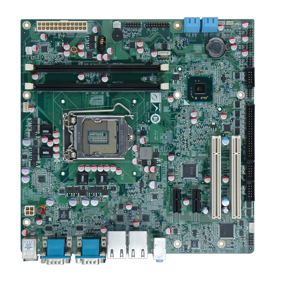
IMB-H612 Mic ro -ATX Mo th e rb o a rd 1.1 In tro d u c tio n Figure 1-1: IMB-H612 The IMB-H612 is a Micro-ATX motherboard. It accepts a LGA1155 Intel® Core™ i3/i5/i7 processor and supports two 240-pin 1333/1066 MHz dual-channel DDR3 DIMM modules up to 16 GB. -
Page 18: Benefits
IMB-H612 Mic ro -ATX Mo th e rb o a rd 1.3 Be n e fits Some of the IMB-H612 motherboard benefits include: Powerful graphics with multiple monitors Staying connected with both wired LAN connections Speedy running of multiple programs and applications 1.4 Fe a tu re s... -
Page 19: Connectors
IMB-H612 Mic ro -ATX Mo th e rb o a rd 1.5 Co n n e c to rs The connectors on the IMB-H612 are shown in the figure below. Figure 1-2: Connectors P a g e 4... -
Page 20: Dimensions
IMB-H612 Mic ro -ATX Mo th e rb o a rd 1.6 Dim e n s io n s The main dimensions of the IMB-H612 are shown in the diagram below. Length: 244 mm Width: 244 mm Figure 1-3: IMB-H612 Dimensions (mm) -
Page 21: Data Flow
IMB-H612 Mic ro -ATX Mo th e rb o a rd 1.7 Da ta Flow Figure 1-4 shows the data flow between the system chipset, the CPU and other components installed on the motherboard. Figure 1-4: Data Flow Diagram P a g e 6... -
Page 22: Technical Specifications
IMB-H612 Mic ro -ATX Mo th e rb o a rd 1.8 Te c h n ic a l Sp e c ific a tio n s IMB-H612 technical specifications are listed below. Specification/Model IMB-H612 Form Factor Micro-ATX CPU Supported LGA1155 socket supports Intel®... -
Page 23: Table 1-2: Imb-H612 Specifications
IMB-H612 Mic ro -ATX Mo th e rb o a rd Specification/Model IMB-H612 Display Port VGA1 integrated in Intel® H61 VGA2 integrated in Chrontel CH7317B Ethernet Two RJ-45 ports One external PS/2 keyboard/mouse port Keyboard/Mouse One 20-pin header Front Audio... -
Page 24: Packing List
IMB-H612 Mic ro -ATX Mo th e rb o a rd Ch a p te r P a c kin g Lis t P a g e 9... -
Page 25: Anti Static Precautions
IMB-H612 Mic ro -ATX Mo th e rb o a rd 2.1 An ti-s ta tic P re c a u tio n s WARNING! Static electricity can destroy certain electronics. Make sure to follow the ESD precautions to prevent damage to the product, and injury to the user. -
Page 26: Packing List
IMB-H612 Mic ro -ATX Mo th e rb o a rd 2.3 P a c kin g Lis t NOTE: If any of the components listed in the checklist below are missing, do not proceed with the installation. Contact the IEI reseller or vendor the IMB-H612 was purchased from or contact an IEI sales representative directly by sending an email to sales@iei.com.tw. -
Page 27: Optional Items
IMB-H612 Mic ro -ATX Mo th e rb o a rd Qu a n tity Ite m a n d P a rt Nu m b e r Im a g e Quick Installation Guide Table 2-1: Packing List 2.4 Op tio n a l Ite m s... -
Page 28: Table 2-2: Optional Items
IMB-H612 Mic ro -ATX Mo th e rb o a rd Ite m a n d P a rt Nu m b e r Im a g e LGA1155/LGA1156 cooler kit, 1U Chassis compatible, 65W (P/N: CF-1156D-RS) Quad-port RS-232 cable without bracket (400/400/400/400MM) -
Page 29: Connectors
IMB-H612 Mic ro -ATX Mo th e rb o a rd Ch a p te r Co n n e c to rs P a g e 14... -
Page 30: Peripheral Interface Connectors
IMB-H612 Mic ro -ATX Mo th e rb o a rd 3.1 P e rip h e ra l In te rfa c e Co n n e c to rs This chapter details all the jumpers and connectors. 3.1.1 IMB-H612 La yo u t The figure below show all the connectors and jumpers. -
Page 31: Peripheral Interface Connectors
IMB-H612 Mic ro -ATX Mo th e rb o a rd 3.1.2 P e rip h e ra l In te rfa c e Co n n e c to rs The table below lists all the connectors on the board. -
Page 32: External Interface Panel Connectors
IMB-H612 Mic ro -ATX Mo th e rb o a rd Co n n e c to r Typ e La b e l USB connectors 8-pin header USB45, USB67, USB89 Table 3-1: Peripheral Interface Connectors 3.1.3 Exte rn a l In te rfa c e P a n e l Co n n e c to rs The table below lists the connectors on the external I/O panel. -
Page 33: Battery Connector
IMB-H612 Mic ro -ATX Mo th e rb o a rd Figure 3-2: ATX Power Connector Location Description Description +3.3 V +3.3V +5 V +5 V PWROK 5VSB +12 V +12 V +3.3V +3.3 V -12V PSON +5 V +5 V... -
Page 34: Cpu Fan Connector
IMB-H612 Mic ro -ATX Mo th e rb o a rd Battery holder CN Typ e : See Figure 3-3 CN Lo c a tio n : The battery connector is connected to the system battery. The battery provides power to the system clock to retain the time when power is turned off. -
Page 35: Cpu Power Connector
IMB-H612 Mic ro -ATX Mo th e rb o a rd Figure 3-4: CPU Fan Connector Location PIN NO. DESCRIPTION VCC12 FANIO1 FANOUT1 Table 3-4: CPU Fan Connector Pinouts 3.2.4 CP U P owe r Co n n e c to r... -
Page 36: Ddr3 Dimm Slots
IMB-H612 Mic ro -ATX Mo th e rb o a rd Figure 3-5: CPU Power Connector Location PIN NO. DESCRIPTION +12V +12V Table 3-5: CPU Power Connector Pinouts 3.2.5 DDR3 DIMM S lo ts CN La b e l: CHA_DIMM1, CHB_DIMM1... -
Page 37: Digital I/O Connector
IMB-H612 Mic ro -ATX Mo th e rb o a rd Figure 3-6: DDR3 DIMM Slot Locations 3.2.6 Dig ita l I/O Co n n e c to r CN La b e l: DIO1 CN Typ e : 10-pin header... -
Page 38: Front Panel Audio Connector
IMB-H612 Mic ro -ATX Mo th e rb o a rd Figure 3-7: Digital I/O Connector Location PIN NO. DESCRIPTION PIN NO. DESCRIPTION DGPO3 DGPO2 DGPO1 DGPO0 DGPI3 DGPI2 DGPI1 DGPI0 Table 3-6: Digital I/O Connector Pinouts 3.2.7 Fro n t P a n e l Au d io Co n n e c to r... -
Page 39: Front Panel Connector
IMB-H612 Mic ro -ATX Mo th e rb o a rd Figure 3-8: Front Panel Audio Connector Location Description Description MIC_L MIC_R FP_AUO_DETECT LINE2_R F_SENCE LINE2_L Table 3-7: Front Panel Audio Connector Pinouts 3.2.8 Fro n t P a n e l Co n n e c to r... -
Page 40: I2C Connector
IMB-H612 Mic ro -ATX Mo th e rb o a rd Figure 3-9: Front Panel Connector Location FUNCTION DESCRIPTION FUNCTION DESCRIPTION ACPILED BEEP_PWR PWR_LED BUZZER Power button PC_BEEP PWR_BTN IDELED RESET External reset HDD_LED SATALED#- Table 3-8: Front Panel Connector Pinouts 3.2.9 I2C Co n n e c to r... -
Page 41: Pci Slot
IMB-H612 Mic ro -ATX Mo th e rb o a rd The I2C connector is for system debug. Figure 3-10: I2C Connector Location Description +5V_DUAL PCH_GP38_PU PCH_GP39_PU Table 3-9: I2C Connector Pinouts 3.2.10 P CI S lo t P CI1,P CI2... -
Page 42: Pcie X1 Slots
IMB-H612 Mic ro -ATX Mo th e rb o a rd Figure 3-11: PCI Slot Locations 3.2.11 P CIe x1 S lo ts CN La b e l: P CIEX1_S LOT1, P CIEX1_S LOT2 PCIe x1 slot CN Typ e :... -
Page 43: Sata 3Gb/S Drive Connectors
IMB-H612 Mic ro -ATX Mo th e rb o a rd Figure 3-12: PCIe x1 Slot Locations 3.2.12 S ATA 3Gb /s Drive Co n n e c to rs CN La b e l: S ATA12, S ATA34 14-pin SATA connector... -
Page 44: Serial Port Connector, Rs-422/485
IMB-H612 Mic ro -ATX Mo th e rb o a rd Figure 3-13: SATA 3Gb/s Drive Connector Locations Description Description TXP_A TXN_A RXN_A RXP_N TXP_B TXN_B RXN_B RXP_B Table 3-10: SATA 3Gb/s Drive Connector Pinouts 3.2.13 S e ria l P o rt Co n n e c to r, RS -422/485... -
Page 45: Serial Port Connectors, Rs-232
IMB-H612 Mic ro -ATX Mo th e rb o a rd This connector provides RS-422 or RS-485 communications. Figure 3-14: Serial Port Connector ( RS-422/485) Location PIN NO. DESCRIPTION PIN NO. DESCRIPTION RXD485# RXD485 TXD485 TXD485# Table 3-11: Serial Port Connector ( RS-422/485) Pinouts 3.2.14 S e ria l P o rt Co n n e c tors , RS -232... -
Page 46: Figure 3-15: Serial Port Connector ( Rs-232) Locations
IMB-H612 Mic ro -ATX Mo th e rb o a rd Figure 3-15: Serial Port Connector ( RS-232) Locations PIN NO. DESCRIPTION PIN NO. DESCRIPTION DCD3/4/5 DSR3/4/5 RXD3/4/5 RTS3/4/5 TXD3/4/5 CTS3/4/5 DTR3/4/5 RI3/4/5 Table 3-12: Serial Port Connector Pinouts (COM3, COM4, COM5) PIN NO. -
Page 47: Smbus Connector
IMB-H612 Mic ro -ATX Mo th e rb o a rd PIN NO. DESCRIPTION PIN NO. DESCRIPTION DCD9 DSR9 RXD9 RTS9 TXD9 CTS9 DTR9 DCD10 DSR10 RXD10 RTS10 TXD10 CTS10 DTR10 RI10 Table 3-13: Serial Port Connector Pinouts (COM7-10) 3.2.15 S MBu s Co n n e c to r... -
Page 48: Spi Connector
IMB-H612 Mic ro -ATX Mo th e rb o a rd Figure 3-16: SMBus Connector Location DESCRIPTION +5V_DUAL SMBCLK_RESUME SMBDATA_RESUME Table 3-14: SMBus Connector Pinouts 3.2.16 S P I Co n n e c to r CN La b e l:... -
Page 49: System Fan Connector
IMB-H612 Mic ro -ATX Mo th e rb o a rd Figure 3-17: SPI Connector Location PIN NO. DESCRIPTION PIN NO. DESCRIPTION SPI_VCC SPI_CS0# SPI_CLK SPI_MISO SPI_MOSI Table 3-15: SPI Connector Pinouts 3.2.17 S ys te m Fa n Co n n e c to r... -
Page 50: Tpm Connector
IMB-H612 Mic ro -ATX Mo th e rb o a rd Figure 3-18: System Fan Connector Locations PIN NO. DESCRIPTION VCC12 Table 3-16: System Fan Connector Pinouts 3.2.18 TP M Co n n e c to r CN La b e l:... -
Page 51: Usb Connectors
IMB-H612 Mic ro -ATX Mo th e rb o a rd Figure 3-19: TPM Connector Location PIN NO. DESCRIPTION PIN NO. DESCRIPTION Clock Frame# NC(KEY) Reset# LAD3 LAD2 +3.3V LAD1 LAD0 SMB CLK SMB DATA +3.3V Standby Serial IRQ Clock Run#... -
Page 52: Figure 3-20: Usb Connector Pinout Locations
IMB-H612 Mic ro -ATX Mo th e rb o a rd See Table 3-18, Table 3-19 and Table 3-20 CN P in o u ts : The USB connectors connect to USB devices. Each pin header provides two USB ports. -
Page 53: External Peripheral Interface Connector Panel
IMB-H612 Mic ro -ATX Mo th e rb o a rd PIN NO. DESCRIPTION PIN NO. DESCRIPTION DATA10_N DATA11_P DATA10_P DATA11_N Table 3-20: USB Port Connector Pinouts (USB89) 3.3 Exte rn a l P e rip h e ra l In te rfa c e Co n n e c to r P a n e l The figure below shows the external peripheral interface connector (EPIC) panel. -
Page 54: Figure 3-22: Audio Connector
IMB-H612 Mic ro -ATX Mo th e rb o a rd See Figure 3-21 CN Lo c a tio n : See Table 3-21 CN P in o u ts : The audio jacks connect to external audio devices. ... -
Page 55: Ethernet And Usb Connectors
IMB-H612 Mic ro -ATX Mo th e rb o a rd 3.3.2 Eth e rn e t a n d US B Con n e c to rs CN La b e l: LAN1_US B01, LAN2_US B23 RJ-45, USB CN Typ e :... -
Page 56: Keyboard/Mouse Connector
IMB-H612 Mic ro -ATX Mo th e rb o a rd DESCRIPTION DESCRIPTION DATA8_N DATA9_N DATA8_P DATA9_P Table 3-23: USB Connector Pinouts (USB01) DESCRIPTION DESCRIPTION DATA2_N DATA3_N DATA2_P DATA3_P Table 3-24: USB Connector Pinouts (USB23) 3.3.3 Ke yb o a rd /Mo u s e Co n n e c to r... -
Page 57: Serial Port Connectors
IMB-H612 Mic ro -ATX Mo th e rb o a rd 3.3.4 RS -232 S e ria l P o rt Co n n e c to rs CN La b e l: COM1, COM2 DB-9 Male CN Typ e :... -
Page 58: Figure 3-25: Vga Connector
IMB-H612 Mic ro -ATX Mo th e rb o a rd Figure 3-25: VGA Connector DESCRIPTION DESCRIPTION CRT_RED CRT_GREEN CRT_BLUE CRT_VCC CRT_PLUG# CRT_DDC_DATA CRT_HSYNC CRT_VSYNC CRT_DDC_CLK Table 3-27: VGA Connector Pinouts (VGA1,VGA2) P a g e 43... -
Page 59: Installation
IMB-H612 Mic ro -ATX Mo th e rb o a rd Ch a p te r In s ta lla tio n P a g e 44... -
Page 60: Anti - Static Precautions
Electrostatic discharge (ESD) can cause serious damage to electronic components, including the IMB-H612. Dry climates are especially susceptible to ESD. It is therefore critical that whenever the IMB-H612 or any other electrical component is handled, the following anti-static precautions are strictly adhered to. - Page 61 Turn all power to the IMB-H612 off: When working with the IMB-H612, make sure that it is disconnected from all power supplies and that no electricity is being fed into the system. Before and during the installation of the IMB-H612 DO NOT: ...
-
Page 62: Basic Installation
Running a CPU without a cooling kit may also result in injury to the user. The CPU, CPU cooling kit and DIMM are the most critical components of the IMB-H612. If one of these component is not installed the IMB-H612 cannot run. -
Page 63: Figure 4-1: Disengage The Cpu Socket Load Lever
IMB-H612 Mic ro -ATX Mo th e rb o a rd Figure 4-1: Disengage the CPU Socket Load Lever Open the socket and remove the protective cover. The black protective S te p 2: cover can be removed by pulling up on the tab labeled “Remove”. See Figure 4-2. -
Page 64: Figure 4-3: Insert The Socket Lga1155 Cpu
IMB-H612 Mic ro -ATX Mo th e rb o a rd S te p 5: Correctly position the CPU. Match the Pin 1 mark with the CPU edge on the CPU socket. Align the CPU pins. Locate pin 1 and the two orientation notches on the CPU. -
Page 65: Cooling Kit Installation
IMB-H612 Mic ro -ATX Mo th e rb o a rd Figure 4-4: Close the Socket LGA1155 Connect the 12 V power to the board. Connect the 12 V power from the power S te p 9: supply to the board. -
Page 66: Figure 4-6: Cooling Kit Support Bracket
IMB-H612 Mic ro -ATX Mo th e rb o a rd WARNING: Do not wipe off (accidentally or otherwise) the pre-sprayed layer of thermal paste on the bottom of the heat sink. The thermal paste between the CPU and the heat sink is important for optimum heat dissipation. -
Page 67: Dimm Installation
Connect the fan cable. Connect the cooling kit fan cable to the fan connector S te p 5: on the IMB-H612. Carefully route the cable and avoid heat generating chips and fan blades. 4.3.3 DIMM In s ta lla tio n To install a DIMM, please follow the steps below and refer to Figure 4-7. -
Page 68: Jumper Settings
Figure 4-8: Jumper Locations plastic clip from a jumper. The jumpers on the IMB-H612 must be set in accordance with the desired configuration before installation. The jumpers on the IMB-H612 are listed in Table 4-1. De s c rip tio n... -
Page 69: Clear Cmos Jumper
J u m p e r Lo c a tio n : If the IMB-H612 fails to boot due to improper BIOS settings, the clear CMOS jumper clears the CMOS data and resets the system BIOS information. To do this, use the jumper cap to close pins 2 and 3 for a few seconds then reinstall the jumper clip back to pins 1 and 2. -
Page 70: Usb Power Select Jumpers
IMB-H612 Mic ro -ATX Mo th e rb o a rd If the “CMOS Settings Wrong” message is displayed during the boot up process, the fault may be corrected by pressing the F1 to enter the CMOS Setup menu. Do one of the following: ... -
Page 71: Internal Peripheral Device Connections
This section outlines the installation of peripheral devices to the onboard connectors. 4.5.1 S ATA Drive Co n n e c tio n The IMB-H612 is shipped with four SATA drive cables. To connect the SATA drives to the connectors, please follow the steps below. -
Page 72: Figure 4-12: Sata Drive Cable Connection
IMB-H612 Mic ro -ATX Mo th e rb o a rd Figure 4-12: SATA Drive Cable Connection Connect the cable to the SATA disk. Connect the connector on the other end S te p 3: of the cable to the connector at the back of the SATA drive. See Figure 4-13. -
Page 73: External Peripheral Interface Connection
4.6.1 Au d io Co n n e c tio n The audio jacks on the external audio connector enable the IMB-H612 to be connected to a stereo sound setup. Each jack supports both input and output. When connecting a device, the High Definition Audio utility will automatically detect input or output. -
Page 74: Lan Connection
IMB-H612 Mic ro -ATX Mo th e rb o a rd Line In port (Light Blue): Connects a CD-ROM, DVD player, or other audio devices. Line Out port (Lime): Connects to a headphone or a speaker. Microphone (Pink): Connects a microphone. -
Page 75: Ps/2 Keyboard And Mouse Connection
4.6.3 P S /2 Ke yb o a rd a n d Mo u s e Co n n e c tio n The IMB-H612 has a dual PS/2 connector on the external peripheral interface panel. The dual PS/2 connector is used to connect to a keyboard and mouse to the system. Follow the steps below to connect a keyboard and mouse to the IMB-H612. -
Page 76: Serial Device Connection
4.6.4 S e ria l De vic e Co n n e c tio n The IMB-H612 has two DB-9 male connectors on the external peripheral interface panel for serial devices. Follow the steps below to connect serial devices to the IMB-H612. S te p 1: Locate the DB-9 connector. -
Page 77: Usb Connection
4.6.5 US B Co n n e c tio n The external USB Series "A" receptacle connectors provide easier and quicker access to external USB devices. Follow the steps below to connect USB devices to the IMB-H612. Locate the USB Series "A" receptacle connectors. The location of the USB S te p 1: Series "A"... -
Page 78: Vga Monitor Connection
4.6.6 VGA Mo n ito r Co n n e c tio n The IMB-H612 has two female DB-15 connectors on the external peripheral interface panel. The DB-15 connector is connected to a CRT or VGA monitor. To connect a monitor to the IMB-H612, please follow the instructions below. -
Page 79: Figure 4-19: Vga Connector
IMB-H612 Mic ro -ATX Mo th e rb o a rd Figure 4-19: VGA Connector Secure the connector. Secure the DB-15 VGA connector from the VGA S te p 4: monitor to the external interface by tightening the two retention screws on either side of the connector. -
Page 80: Bios
IMB-H612 Mic ro -ATX Mo th e rb o a rd Ch a p te r BIOS P a g e 65... -
Page 81: Introduction
IMB-H612 Mic ro -ATX Mo th e rb o a rd 5.1 In tro d u c tio n The BIOS is programmed onto the BIOS chip. The BIOS setup program allows changes to certain system settings. This chapter outlines the options that can be changed. -
Page 82: Getting Help
IMB-H612 Mic ro -ATX Mo th e rb o a rd Ke y Fu n c tio n F2 key Load previous values. F3 key Load optimized defaults F4 key Save changes and Exit BIOS Table 5-1: BIOS Navigation Keys 5.1.3 Ge ttin g He lp... -
Page 83: Main
IMB-H612 Mic ro -ATX Mo th e rb o a rd 5.2 Ma in The Main BIOS menu (BIOS Menu 1) appears when the BIOS Setup program is entered. The Main menu gives an overview of the basic system information. -
Page 84: Advanced
IMB-H612 Mic ro -ATX Mo th e rb o a rd The System Overview field also has two user configurable fields: S ys te m Da te [xx/xx/xx] Use the System Date option to set the system date. Manually enter the day, month and year. -
Page 85: Acpi Settings
IMB-H612 Mic ro -ATX Mo th e rb o a rd Aptio Setup Utility – Copyright (C) 2011 American Megatrends, Inc. Main Advanced Chipset Boot Security Save & Exit > ACPI Settings System ACPI Parameters > Trusted Computing > CPU Configuration >... -
Page 86: Trusted Computing
IMB-H612 Mic ro -ATX Mo th e rb o a rd ACP I S le e p Sta te [S 1 (CP U Sto p Clo c k)] Use the ACPI Sleep State option to specify the sleep state the system enters when it is not being used. -
Page 87: Cpu Configuration
IMB-H612 Mic ro -ATX Mo th e rb o a rd TPM S u p p o rt [Dis a b le ] Use the TPM Support option to configure support for the TPM. TPM support is disabled. -
Page 88: Cpu Information
IMB-H612 Mic ro -ATX Mo th e rb o a rd 5.3.3.1 CP U In fo rm a tio n Use the CPU Information submenu (BIOS Menu 6) to view detailed CPU specifications and configure the CPU. Aptio Setup Utility – Copyright (C) 2011 American Megatrends, Inc. -
Page 89: Sata Configuration
IMB-H612 Mic ro -ATX Mo th e rb o a rd L2 Cache: Lists the amount of storage space on the L2 cache. L3 Cache: Lists the amount of storage space on the L3 cache. 5.3.4 S ATA Co n fig u ra tio n Use the SATA Configuration menu (BIOS Menu 7) to change and/or set the configuration of the SATA devices installed in the system. -
Page 90: Intel Txt(Lt) Configuration
IMB-H612 Mic ro -ATX Mo th e rb o a rd Disables Serial-ATA controller. Disable Enhanced Configures the Serial-ATA controller to be in enhanced mode. In this mode, IDE channels and SATA channels are separated. Some legacy OS do not support this mode. -
Page 91: Usb Configuration
IMB-H612 Mic ro -ATX Mo th e rb o a rd Aptio Setup Utility – Copyright (C) 2011 American Megatrends, Inc. Advanced Intel Trusted Execution Technology Configuration Intel TXT support only can be enabled/disabled if SMX is enabled. VT and VT-d support must also be enabled prior --------------------- : Select Screen... - Page 92 IMB-H612 Mic ro -ATX Mo th e rb o a rd US B De vic e s The USB Devices Enabled field lists the USB devices that are enabled on the system US B S u p p o rt [En a b le d ] Use the USB Support option to enable or disable USB support on the system.
-
Page 93: Super Io Configuration
IMB-H612 Mic ro -ATX Mo th e rb o a rd 5.3.7 S u pe r IO Co n fig u ra tio n Use the Super IO Configuration menu (BIOS Menu 10) to set or change the configurations for the FDD controllers, parallel ports and serial ports. -
Page 94: Serial Port N Configuration
IMB-H612 Mic ro -ATX Mo th e rb o a rd 5.3.7.1 S e ria l P o rt n Co n fig u ra tio n Use the Serial Port n Configuration menu (BIOS Menu 11) to configure the serial port n. - Page 95 IMB-H612 Mic ro -ATX Mo th e rb o a rd Serial Port I/O port address is 3F8h and the interrupt IO=3F8h; IRQ=3, 4 address is IRQ3,4 IO=2F8h; Serial Port I/O port address is 2F8h and the interrupt...
- Page 96 IMB-H612 Mic ro -ATX Mo th e rb o a rd Serial Port I/O port address is 2C8h and the interrupt IO=2C8h; IRQ=10, 11 address is IRQ10, 11 5.3.7.1.3 S e ria l P o rt 3 Co n fig u ra tio n ...
- Page 97 IMB-H612 Mic ro -ATX Mo th e rb o a rd 5.3.7.1.4 S e ria l P o rt 4 Co n fig u ra tio n S e ria l P o rt [En a b le d ] Use the Serial Port option to enable or disable the serial port.
- Page 98 IMB-H612 Mic ro -ATX Mo th e rb o a rd Enable the serial port Enabled EFAULT Ch a n g e S e ttin g s [Au to ] Use the Change Settings option to change the serial port IO port address and interrupt address.
-
Page 99: H/W Monitor
IMB-H612 Mic ro -ATX Mo th e rb o a rd Ch a n g e S e ttin g s [Au to ] Use the Change Settings option to change the serial port IO port address and interrupt address. -
Page 100: Bios Menu 12: H/W Monitor
IMB-H612 Mic ro -ATX Mo th e rb o a rd Aptio Setup Utility – Copyright (C) 2011 American Megatrends, Inc. Advanced PC Health Status Smart FAN Configuration CPU Temperature :+50 C SYS Temperature :+44 C CPU FAN Speed :2189 RPM... -
Page 101: Fan 1 Configuration
IMB-H612 Mic ro -ATX Mo th e rb o a rd 5.3.8.1 FAN 1 Co n fig u ra tio n Use the FAN 1 Configuration submenu (BIOS Menu 13) to configure fan 1 temperature and speed settings. Aptio Setup Utility – Copyright (C) 2011 American Megatrends, Inc. -
Page 102: Fan 2 Configuration
IMB-H612 Mic ro -ATX Mo th e rb o a rd Ta rg e t Te m p . S e n s o r [CP U Te m p e ra tu re ] Use the Target Temp. Sensor option to set the target CPU temperature. -
Page 103: Bios Menu 14: Fan 2 Configuration
IMB-H612 Mic ro -ATX Mo th e rb o a rd Aptio Setup Utility – Copyright (C) 2011 American Megatrends, Inc. Advanced PC Health Status SYS Smart Fan control [Auto by Duty-Cycle] Target Temp Sensor [CPU Temperature] Temperature Bound 1... -
Page 104: Secondary Super Io Configuration
IMB-H612 Mic ro -ATX Mo th e rb o a rd Sets the target temperature sensor to the System Temperature setting. Temperature Te m p e ra tu re Bo u n d n Use the + or – key to change the fan Temperature Bound n value. Enter a decimal number between 0 and 127. -
Page 105: Serial Port 7 Configuration
IMB-H612 Mic ro -ATX Mo th e rb o a rd 5.3.9.1 S e ria l P o rt 7 Co n fig u ra tio n S e ria l P o rt [En a b le d ] Use the Serial Port option to enable or disable the serial port. -
Page 106: Serial Port 8 Configuration
IMB-H612 Mic ro -ATX Mo th e rb o a rd Enables the serial port to function in normal Normal EFAULT mode. Mode, Pusle Enables the serial port to function in IR mode, pulse 1.6 us at full duplex. -
Page 107: Serial Port 9 Configuration
IMB-H612 Mic ro -ATX Mo th e rb o a rd Serial Port I/O port address is 2C0h and the interrupt IO=2C0h; IRQ=10, 11 address is IRQ10, 11 IO=2C8h; Serial Port I/O port address is 2C8h and the interrupt... -
Page 108: Serial Port 10 Configuration
IMB-H612 Mic ro -ATX Mo th e rb o a rd Serial Port I/O port address is 2B0h and the interrupt IO=2B0h; IRQ=10, 11 address is IRQ10, 11 IO=2B8h; Serial Port I/O port address is 2B8h and the interrupt... -
Page 109: Serial Port Console Redirection
IMB-H612 Mic ro -ATX Mo th e rb o a rd 5.3.10 S e ria l P o rt Co n s o le Re d ire c tio n The Serial Port Console Redirection menu (BIOS Menu 16) allows the console redirection options to be configured. -
Page 110: Bios Menu 16: Serial Port Console Redirection
IMB-H612 Mic ro -ATX Mo th e rb o a rd Aptio Setup Utility – Copyright (C) 2011 American Megatrends, Inc. Advanced COM1 Console Redirection Console Redirection [Disabled] Enable or Disable > Console Redirection Settings COM2 Console Redirection [Disabled] > Console Redirection Settings... -
Page 111: Iei Feature
IMB-H612 Mic ro -ATX Mo th e rb o a rd Disabled the console redirection function Disabled Enabled Enabled the console redirection function EFAULT 5.3.11 IEI Fe a tu re Use the IEI Feature menu (BIOS Menu 17) to configure One Key Recovery function. -
Page 112: Chipset
IMB-H612 Mic ro -ATX Mo th e rb o a rd 5.4 Ch ips e t Use the Chipset menu (BIOS Menu 18) to access the Northbridge, Southbridge, Integrated Graphics, and ME Subsystem configuration menus. WARNING! Setting the wrong values for the Chipset BIOS selections in the Chipset BIOS menu may cause the system to malfunction. -
Page 113: Northbridge Configuration
IMB-H612 Mic ro -ATX Mo th e rb o a rd 5.4.1 No rth b rid g e Co n fig u ra tio n Use the Northbridge Chipset Configuration menu (BIOS Menu 19) to configure the Northbridge chipset. Aptio Setup Utility – Copyright (C) 2011 American Megatrends, Inc. - Page 114 IMB-H612 Mic ro -ATX Mo th e rb o a rd IGD Me m o ry [64 M] Use the IGD Memory option to specify the amount of system memory that can be used by the Internal graphics device.
-
Page 115: Southbridge Configuration
IMB-H612 Mic ro -ATX Mo th e rb o a rd 480 MB of memory used by internal graphics 480 M device 512 M 512 MB of memory used by internal graphics device P CI Exp re s s P o rt [En a b le d ] Use the PCI Express Port option to enable or disable the PCI Express port. -
Page 116: Bios Menu 20: Southbridge Chipset Configuration
IMB-H612 Mic ro -ATX Mo th e rb o a rd Aptio Setup Utility – Copyright (C) 2011 American Megatrends, Inc. Chipset Auto Power Button Status [OFF] Enabled/Disabled All USB controllers USB Controller [Enabled] Wake Event Configuration Restore AC Power Loss... - Page 117 IMB-H612 Mic ro -ATX Mo th e rb o a rd The system returns to its previous state. If it was on, it Last State turns itself on. If it was off, it remains off. Re s u m e o n P CIe Wa ke [En a b le d ] Use the Resume on PCIe Wake option to enable or disable resuming from the PCIe wake message and WAKE# signal.
-
Page 118: Integrated Graphics
IMB-H612 Mic ro -ATX Mo th e rb o a rd The onboard High Definition Audio controller is disabled Disabled Enabled The onboard High Definition Audio controller is detected EFAULT automatically and enabled Aza lia in te rn a l HDMI c o d e c [En a b le d ] Use the Azalia internal HDMI codec option to enable or disable the internal HDMI codec for High Definition Audio. -
Page 119: Bios Menu 21: Integrated Graphics
IMB-H612 Mic ro -ATX Mo th e rb o a rd Aptio Setup Utility – Copyright (C) 2011 American Megatrends, Inc. Advanced Intel IGD SWSCI OpRegion Configuration Select DVMT Mode used by Internal Graphics DVMT Mode Select [DVMT Mode] Device. If Fixed Mode... -
Page 120: Me Subsystem
IMB-H612 Mic ro -ATX Mo th e rb o a rd IGD - Bo o t Typ e [AUTO] Use the IGD - Boot Type option to select the display device used by the system when it boots. For dual display support, select “Auto.” Configuration options are listed below. -
Page 121: Boot
IMB-H612 Mic ro -ATX Mo th e rb o a rd Un c o n fig u re AMT/ME [Dis a b le d ] Use the Unconfigure AMT/ME option to perform AMT/ME unconfigure without password operation. Not perform AMT/ME unconfigure... -
Page 122: Security
IMB-H612 Mic ro -ATX Mo th e rb o a rd Allows the Number Lock on the keyboard to be EFAULT enabled automatically when the computer system boots up. This allows the immediate use of the 10-key numeric keypad located on the right side of the keyboard. -
Page 123: Save & Exit
IMB-H612 Mic ro -ATX Mo th e rb o a rd Aptio Setup Utility – Copyright (C) 2011 American Megatrends, Inc. Main Advanced Chipset Boot Security Save & Exit Password Description Set Setup Administrator Password If ONLY the Administrator’s password is set, then this only limits access to Setup and is only asked for when entering Setup. -
Page 124: Bios Menu 25: Save & Exit
IMB-H612 Mic ro -ATX Mo th e rb o a rd Aptio Setup Utility – Copyright (C) 2011 American Megatrends, Inc. Main Advanced Chipset Boot Security Save & Exit Save Changes and Reset Reset the system after Discard Changes and Reset saving the changes. -
Page 125: Software Drivers
IMB-H612 Mic ro -ATX Mo th e rb o a rd Chapter S o ftwa re Drive rs P a g e 110... -
Page 126: Available Software Drivers
Installation instructions are given below. 6.2 S o ftwa re In s ta lla tio n All the drivers for the IMB-H612 are on the CD that came with the system. To install the drivers, please follow the steps below. -
Page 127: Figure 6-1: Introduction Screen
IMB-H612 Mic ro -ATX Mo th e rb o a rd Figure 6-1: Introduction Screen S te p 3: Click IMB-H612. A new screen with a list of available drivers appears (Figure 6-2). S te p 4: Figure 6-2: Available Drivers... -
Page 128: Chipset Driver Installation
IMB-H612 Mic ro -ATX Mo th e rb o a rd S te p 5: Install all of the necessary drivers in this menu. 6.3 Ch ips e t Drive r In s ta lla tio n To install the chipset driver, please do the following. -
Page 129: Figure 6-4: Chipset Driver Welcome Screen
IMB-H612 Mic ro -ATX Mo th e rb o a rd Figure 6-4: Chipset Driver Welcome Screen S te p 7: The license agreement in Figure 6-5 appears. Read the License Agreement. S te p 8: Click Yes to continue. -
Page 130: Figure 6-6: Chipset Driver Read Me File
IMB-H612 Mic ro -ATX Mo th e rb o a rd The Read Me file in Figure 6-6 appears. S te p 10: Click Next to continue. S te p 11: Figure 6-6: Chipset Driver Read Me File Setup Operations are performed as shown in Figure 6-7. -
Page 131: Figure 6-7: Chipset Driver Setup Operations
IMB-H612 Mic ro -ATX Mo th e rb o a rd Figure 6-7: Chipset Driver Setup Operations S te p 14: The Finish screen in Figure 6-8 appears. Select “Yes, I want to restart this computer now” and click Finish.S te p 0:... -
Page 132: Graphics Driver Installation
IMB-H612 Mic ro -ATX Mo th e rb o a rd 6.4 Gra p h ic s Drive r In s ta lla tio n To install the Graphics driver, please do the following. S te p 1: Access the driver list. (See Section 6.2) Click “VGA”... -
Page 133: Figure 6-10: Graphics Driver License Agreement
IMB-H612 Mic ro -ATX Mo th e rb o a rd Figure 6-10: Graphics Driver License Agreement Setup Operations are performed as shown in Figure 6-11. S te p 8: S te p 9: Once the Setup Operations are complete, click Next to continue. -
Page 134: Lan Driver Installation
IMB-H612 Mic ro -ATX Mo th e rb o a rd The Finish screen in Figure 6-12 appears. S te p 10: Select “Yes, I want to restart this computer now” and click Finish.S te p 0: S te p 11: Figure 6-12: Graphics Driver Installation Finish Screen 6.5 LAN Drive r In s ta lla tio n... -
Page 135: Figure 6-13: Lan Driver Welcome Screen
IMB-H612 Mic ro -ATX Mo th e rb o a rd Figure 6-13: LAN Driver Welcome Screen S te p 5: Click Next to continue. The Ready to Install the Program Screen in Figure 6-14 appears. S te p 6: Click Install to proceed with the installation. -
Page 136: Figure 6-15: Lan Driver Setup Status Screen
IMB-H612 Mic ro -ATX Mo th e rb o a rd The Setup Status screen in Figure 6-15 appears. S te p 9: Figure 6-15: LAN Driver Setup Status Screen When the driver installation is complete, the screen in Figure 6-16 appears. -
Page 137: Audio Driver Installation
IMB-H612 Mic ro -ATX Mo th e rb o a rd 6.6 Au d io Drive r In s ta lla tio n To install the audio driver, please do the following. S te p 1: Access the driver list. (See Section 6.2) Click “Audio”... -
Page 138: Figure 6-18: Audio Driver Welcome Screen
IMB-H612 Mic ro -ATX Mo th e rb o a rd Figure 6-18: Audio Driver Welcome Screen S te p 7: The audio driver installation begins. See Figure 6-19. Figure 6-19: Audio Driver Installation When the installation is complete, the screen in Figure 6-20 appears. -
Page 139: A Bios Options
IMB-H612 Mic ro -ATX Mo th e rb o a rd Ap p e n d ix BIOS Op tio n s P a g e 124... - Page 140 IMB-H612 Mic ro -ATX Mo th e rb o a rd Below is a list of BIOS configuration options in the BIOS chapter. System Overview .........................68 Memory Information ......................68 System Date [xx/xx/xx] ......................69 System Time [xx:xx:xx] .......................69 ...
- Page 141 IMB-H612 Mic ro -ATX Mo th e rb o a rd CPU Smart Fan control [Auto by Duty-Cycle] ..............88 Target Temp. Sensor [CPU Temperature] .................88 Temperature Bound n ......................89 Segment n Speed (PWM) .....................89 Serial Port [Enabled] ......................90 ...
- Page 142 IMB-H612 Mic ro -ATX Mo th e rb o a rd Quiet Boot [Enabled] ......................107 Option ROM Messages [Keep Current] ................107 Administrator Password ....................108 User Password ........................108 Save Changes and Reset ....................109 Discard Changes and Reset .....................109 ...
-
Page 143: B One Key Recovery
IMB-H612 Mic ro -ATX Mo th e rb o a rd Ap p e n d ix On e Ke y Re c o ve ry P a g e 128... -
Page 144: One Key Recovery Introduction
IMB-H612 Mic ro -ATX Mo th e rb o a rd B.1 On e Ke y Re c o ve ry In tro d u c tio n The IEI one key recovery is an easy-to-use front end for the Norton Ghost system backup and recovery tool. -
Page 145: System Requirement
IMB-H612 Mic ro -ATX Mo th e rb o a rd After completing the five initial setup procedures as described above, users can access the recovery tool by pressing <F3> while booting up the system. The detailed information of each function is described in Section B.5. -
Page 146: Supported Operating System
IMB-H612 Mic ro -ATX Mo th e rb o a rd partitions. Please take the following table as a reference when calculating the size of the partition. OS Image after Ghost Compression Ratio Windows® 7 7 GB 5 GB Windows® XPE... -
Page 147: Setup Procedure For Windows
IMB-H612 Mic ro -ATX Mo th e rb o a rd Ubuntu 8.10 (Intrepid) Ubuntu 7.10 (Gutsy) Ubuntu 6.10 (Edgy) Debian 5.0 (Lenny) Debian 4.0 (Etch) SuSe 11.2 SuSe 10.3 NOTE: Installing unsupported OS versions may cause the recovery tool to fail. -
Page 148: Hardware And Bios Setup
IMB-H612 Mic ro -ATX Mo th e rb o a rd B.2.1 Ha rdwa re a n d BIOS S e tu p Make sure the system is powered off and unplugged. S te p 1: Install a hard drive or SSD in the system. An unformatted and unpartitioned disk S te p 2: is recommended. -
Page 149: Figure B-2: Launching The Recovery Tool
IMB-H612 Mic ro -ATX Mo th e rb o a rd Figure B-2: Launching the Recovery Tool The recovery tool setup menu is shown as below. S te p 3: Figure B-3: Recovery Tool Setup Menu Press <6> then <Enter>. -
Page 150: Figure B-4: Command Prompt
IMB-H612 Mic ro -ATX Mo th e rb o a rd Figure B-4: Command Prompt S te p 5: The command prompt window appears. Type the following commands (marked in red) to create two partitions. One is for the OS installation; the other is for saving recovery files and images which will be an invisible partition. -
Page 151: Figure B-5: Partition Creation Commands
IMB-H612 Mic ro -ATX Mo th e rb o a rd Figure B-5: Partition Creation Commands P a g e 136... -
Page 152: Install Operating System, Drivers And Applications
IMB-H612 Mic ro -ATX Mo th e rb o a rd NOTE: Use the following commands to check if the partitions were created successfully. Press any key to exit the recovery tool and automatically reboot the system. S te p 6: Please continue to the following procedure: Build the Recovery Partition.S t e p 0 :... -
Page 153: Building The Recovery Partition
IMB-H612 Mic ro -ATX Mo th e rb o a rd B.2.4 Bu ild in g th e Re c o ve ry P a rtitio n Put the recover CD in the optical drive. S te p 1: Start the system. -
Page 154: Figure B-8: Building The Recovery Partition
IMB-H612 Mic ro -ATX Mo th e rb o a rd S te p 5: The Symantec Ghost window appears and starts configuring the system to build a recovery partition. In this process the partition created for recovery files in Section B.2.2 is hidden and the recovery tool is saved in this partition. -
Page 155: Create Factory Default Image
IMB-H612 Mic ro -ATX Mo th e rb o a rd B.2.5 Cre a te Fa c to ry De fa u lt Im a g e NOTE: Before creating the factory default image, please configure the system to a factory default environment, including driver and application installations. -
Page 156: Figure B-12: About Symantec Ghost Window
IMB-H612 Mic ro -ATX Mo th e rb o a rd Figure B-12: About Symantec Ghost Window S te p 4: Use mouse to navigate to the option shown below (Figure B-13). Figure B-13: Symantec Ghost Path S te p 5: Select the local source drive (Drive 1) as shown in Figure B-14. -
Page 157: Figure B-14: Select A Local Source Drive
IMB-H612 Mic ro -ATX Mo th e rb o a rd Figure B-14: Select a Local Source Drive Select a source partition (Part 1) from basic drive as shown in Figure B-15. S te p 6: Then click OK. Figure B-15: Select a Source Partition from Basic Drive Select 1.2: [Recovery] NTFS drive and enter a file name called... -
Page 158: Figure B-16: File Name To Copy Image To
IMB-H612 Mic ro -ATX Mo th e rb o a rd Figure B-16: File Name to Copy Image to When the Compress Image screen in Figure B-17 prompts, click High to make S te p 8: the image file smaller. -
Page 159: Figure B-18: Image Creation Confirmation
IMB-H612 Mic ro -ATX Mo th e rb o a rd The Proceed with partition image creation window appears, click Yes to S te p 9: continue. Figure B-18: Image Creation Confirmation The Symantec Ghost starts to create the factory default image (Figure B-19). -
Page 160: Auto Recovery Setup Procedure
IMB-H612 Mic ro -ATX Mo th e rb o a rd S te p 12: The recovery tool main menu window is shown as below. Press any key to reboot the system. S t e p 0 : Figure B-21: Press Any Key to Continue B.3 Au to Re c o ve ry S e tu p P ro c e d u re... -
Page 161: Figure B-22: Auto Recovery Utility
IMB-H612 Mic ro -ATX Mo th e rb o a rd Figure B-22: Auto Recovery Utility S te p 3: Reboot the system from the recovery CD. When prompted, press any key to boot from the recovery CD. It will take a while to launch the recovery tool. Please... -
Page 162: Figure B-25: Building The Auto Recovery Partition
IMB-H612 Mic ro -ATX Mo th e rb o a rd S te p 5: The Symantec Ghost window appears and starts configuring the system to build an auto recovery partition. In this process the partition created for recovery files in Section B.2.2 is hidden and the auto recovery tool is saved in this partition. -
Page 163: Figure B-27: Image Creation Complete
IMB-H612 Mic ro -ATX Mo th e rb o a rd The Symantec Ghost starts to create the factory default image (Figure B-27). S te p 7: Figure B-27: Image Creation Complete S te p 8: After completing the system configuration, press any key in the following window to restart the system. -
Page 164: Setup Procedure For Linux
IMB-H612 Mic ro -ATX Mo th e rb o a rd BIOS SETUP UTILITY Main Advanced PCIPNP Boot Security Chipset Exit iEi Feature Auto Recovery Function [Enabled] Recover from PXE [Disabled] Select Screen ↑ ↓ Select Item Enter Go to SubScreen... -
Page 165: Figure B-29: Partitions For Linux
IMB-H612 Mic ro -ATX Mo th e rb o a rd Install Linux operating system. Make sure to install GRUB (v0.97 or earlier) S te p 2: MBR type and Ext3 partition type. Leave enough space on the hard drive to create the recover partition later. -
Page 166: Figure B-30: Manual Recovery Environment For Linux
IMB-H612 Mic ro -ATX Mo th e rb o a rd DISKPART>sel disk 0 DISKPART>create part pri size= DISKPART>assign letter=N DISKPART>exit system32>format N: /fs:ntfs /q /v:Recovery /y system32>exit S te p 4: Build the recovery partition. Press any key to boot from the recovery CD. It will take a while to launch the recovery tool. -
Page 167: Figure B-31: Access Menu.lst In Linux (Text Mode)
IMB-H612 Mic ro -ATX Mo th e rb o a rd Figure B-31: Access menu.lst in Linux (Text Mode) S te p 6: Modify the menu.lst as shown below. S te p 7: The recovery tool menu appears. (Figure B-32) Figure B-32: Recovery Tool Menu Create a factory default image. -
Page 168: Recovery Tool Functions
IMB-H612 Mic ro -ATX Mo th e rb o a rd B.5 Re c o ve ry To o l Fu n c tio n s After completing the initial setup procedures as described above, users can access the recovery tool by pressing <F3> while booting up the system. However, if the setup procedure in Section B.3 has been completed and the auto recovery function is enabled,... -
Page 169: Factory Restore
IMB-H612 Mic ro -ATX Mo th e rb o a rd WARNING: All data in the system will be deleted during the system recovery. Please backup the system files before restoring the system (either Factory Restore or Restore Backup). B.5.1 Fa c to ry Re s to re To restore the factory default image, please follow the steps below. -
Page 170: Backup System
IMB-H612 Mic ro -ATX Mo th e rb o a rd Figure B-35: Recovery Complete Window B.5.2 Ba c ku p S ys te m To backup the system, please follow the steps below. Type <2> and press <Enter> in the main menu. -
Page 171: Restore Your Last Backup
IMB-H612 Mic ro -ATX Mo th e rb o a rd Figure B-37: System Backup Complete Window B.5.3 Re s to re Yo u r La s t Ba c ku p To restore the last system backup, please follow the steps below. -
Page 172: Manual
IMB-H612 Mic ro -ATX Mo th e rb o a rd Figure B-39: Restore System Backup Complete Window B.5.4 Ma n u a l To restore the last system backup, please follow the steps below. Type <4> and press <Enter> in the main menu. -
Page 173: Restore Systems From A Linux Server Through Lan
IMB-H612 Mic ro -ATX Mo th e rb o a rd B.6 Re s to re S ys te m s fro m a Lin u x S e rve r thro u g h LAN The One Key Recovery allows a client system to automatically restore to a factory default image saved in a Linux system (the server) through LAN connectivity after encountering a Blue Screen of Death (BSoD) or a hang for around 10 minutes. -
Page 174: Configure Dhcp Server Settings
IMB-H612 Mic ro -ATX Mo th e rb o a rd The detailed descriptions are described in the following sections. In this document, two types of Linux OS are used as examples to explain the configuration process – CentOS 5.5 (Kernel 2.6.18) and Debian 5.0.7 (Kernel 2.6.26). -
Page 175: Configure Tftp Settings
IMB-H612 Mic ro -ATX Mo th e rb o a rd Edit “/etc/dhcpd.conf” for your environment. For example, add next-server PXE server IP address; filename “pxelinux.0”; B.6.2 Co n fig u re TFTP S e ttin g s S te p 1: Install the tftp, httpd and syslinux. -
Page 176: Configure One Key Recovery Server Settings
IMB-H612 Mic ro -ATX Mo th e rb o a rd Debian Replace the TFTP settings from “inetd” to “xinetd” and annotate the “inetd” by adding “#”. #vi /etc/inetd.conf Modify: #tftp dgram udp wait root /usr/sbin..(as shown below) #vi /etc/xinetd.d/tftp B.6.3 Co n fig u re On e Ke y Re c o ve ry S e rve r S e ttin g s... -
Page 177: Start The Dhcp, Tftp And Http
IMB-H612 Mic ro -ATX Mo th e rb o a rd S te p 2: Extract the recovery package to /. #cp RecoveryR10.tar.bz2 / #cd / #tar –xvjf RecoveryR10.tar.bz2 Copy “pxelinux.0” from “syslinux” and install to “/tftboot”. S te p 3: #cp /usr/lib/syslinux/pxelinux.0 /tftpboot/... - Page 178 IMB-H612 Mic ro -ATX Mo th e rb o a rd WARNING: The file name of the factory default image must be iei.gho. Confirm the operating system default settings: smb.conf. S te p 3: #vi /etc/samba/smb.conf Modify: [image] comment = One Key Recovery...
-
Page 179: Setup A Client System For Auto Recovery
IMB-H612 Mic ro -ATX Mo th e rb o a rd B.6.6 S e tu p a Clie n t S ys te m fo r Au to Re c o ve ry Configure the following BIOS options of the client system. - Page 180 IMB-H612 Mic ro -ATX Mo th e rb o a rd NOTE: A firewall or a SELinux is not in use in the whole setup process. If there is a firewall or a SELinux protecting the system, modify the configuration information to accommodate them.
-
Page 181: Other Information
IMB-H612 Mic ro -ATX Mo th e rb o a rd B.7 Oth e r In fo rm a tio n B.7.1 Us in g AHCI Mo d e o r ALi M5283 / VIA VT6421A Co n tro lle r... - Page 182 IMB-H612 Mic ro -ATX Mo th e rb o a rd When the following window appears, press <S> to select “Specify Additional S te p 5: Device”. In the following window, select a SATA controller mode used in the system. Then S te p 6: press <Enter>.
-
Page 183: System Memory Requirement
IMB-H612 Mic ro -ATX Mo th e rb o a rd S te p 7: After pressing <Enter>, the system will get into the recovery tool setup menu. Continue to follow the setup procedure from Step 4 in Section B.2.2 Create Partitions to finish the whole setup process. -
Page 184: C Terminology
IMB-H612 Mic ro -ATX Mo th e rb o a rd Ap p e n d ix Te rm in o lo g y P a g e 169... - Page 185 IMB-H612 Mic ro -ATX Mo th e rb o a rd AC ’97 Audio Codec 97 (AC’97) refers to a codec standard developed by Intel® in 1997. ACP I Advanced Configuration and Power Interface (ACPI) is an OS-directed configuration, power management, and thermal management interface.
- Page 186 IMB-H612 Mic ro -ATX Mo th e rb o a rd DIMM Dual Inline Memory Modules are a type of RAM that offer a 64-bit data bus and have separate electrical contacts on each side of the module. The digital inputs and digital outputs are general control signals that control the on/off circuit of external devices or TTL devices.
- Page 187 IMB-H612 Mic ro -ATX Mo th e rb o a rd LVDS Low-voltage differential signaling (LVDS) is a dual-wire, high-speed differential electrical signaling system commonly used to connect LCD displays to a computer. P OS T The Power-on Self Test (POST) is the pre-boot actions the system performs when the system is turned-on.
-
Page 188: D Digital I/O Interface
IMB-H612 Mic ro -ATX Mo th e rb o a rd Ap p e n d ix Dig ita l I/O In te rfa c e P a g e 173... -
Page 189: Introduction
D.1 In tro d u c tio n The DIO connector on the IMB-H612 is interfaced to GPIO ports on the Super I/O chipset. The DIO has both 4-bit digital inputs and 4-bit digital outputs. The digital inputs and digital outputs are generally control signals that control the on/off circuit of external devices or TTL devices. -
Page 190: Enable The Dio Output Function
IMB-H612 Mic ro -ATX Mo th e rb o a rd D.3.2 En a b le th e DIO Ou tpu t Fu n c tio n The BIOS interrupt call INT 15H controls the digital I/O. An assembly program to enable digital I/O output functions is listed below. -
Page 191: E Watchdog Timer
IMB-H612 Mic ro -ATX Mo th e rb o a rd Ap p e n d ix Wa tc h d o g Tim e r P a g e 176... - Page 192 IMB-H612 Mic ro -ATX Mo th e rb o a rd NOTE: The following discussion applies to DOS environment. Contact IEI support or visit the IEI website for specific drivers for other operating systems. The Watchdog Timer is provided to ensure that standalone systems can always recover from catastrophic conditions that cause the CPU to crash.
- Page 193 IMB-H612 Mic ro -ATX Mo th e rb o a rd NOTE: When exiting a program it is necessary to disable the Watchdog Timer, otherwise the system resets. EXAMP LE P ROGRAM: ; INITIAL TIMER PERIOD COUNTER W_LOOP: AX, 6F02H ;setting the time-out value...
-
Page 194: F Compatibility
IMB-H612 Mic ro -ATX Mo th e rb o a rd Ap p e n d ix Co m p a tib ility P a g e 179... -
Page 195: Compatible Operating Systems
IMB-H612 Mic ro -ATX Mo th e rb o a rd NOTE: The compatible items described here have been tested by the IEI R&D team and found to be compatible with the IMB-H612 F.1 Co m pa tib le Op e ra tin g S ys te m s The following operating systems have been successfully run on the IMB-H612. -
Page 196: G Hazardous Materials Disclosure
IMB-H612 Mic ro -ATX Mo th e rb o a rd Ap p e n d ix Ha za rd o u s Ma te ria ls Dis c lo s u re P a g e 181... -
Page 197: Hazardous Materials Disclosure Table For Ipb Products Certified As R Ohs Compliant Under 2002/95/Ec Without Mercury
IMB-H612 Mic ro -ATX Mo th e rb o a rd G.1 Ha za rd o u s Ma te ria ls Dis c lo s u re Ta ble for IP B P ro d u c ts Ce rtifie d a s Ro HS Co m p lia n t Un d e r 2002/95/EC With o u t... - Page 198 IMB-H612 Mic ro -ATX Mo th e rb o a rd P a rt Na m e To xic o r Ha za rd o u s S u b s ta n c e s a n d Ele m e n ts...
-
Page 199: P A G E X
IMB-H612 Mic ro -ATX Mo th e rb o a rd 此附件旨在确保本产品符合中国 RoHS 标准。以下表格标示此产品中某有毒物质的含量符 合中国 RoHS 标准规定的限量要求。 本产品上会附有”环境友好使用期限”的标签,此期限是估算这些物质”不会有泄漏或突变”的 年限。本 产品可能包含有较短的环境友好使用期限的可替换元件,像是电池或灯管,这些元 件将会单独标示出来。 部件名称 有毒有害物质或元素 铅 汞 镉 六价铬 多溴联苯 多溴二苯 醚 (P b ) (Hg ) (Cd ) (CR(VI)) (P BB) (P BDE) 壳体...
Need help?
Do you have a question about the IMB-H612 and is the answer not in the manual?
Questions and answers