Sign In
Upload
Manuals
Brands
IEI Technology Manuals
Motherboard
IOWA-8522
IEI Technology IOWA-8522 ISA CPU Manuals
Manuals and User Guides for IEI Technology IOWA-8522 ISA CPU. We have
2
IEI Technology IOWA-8522 ISA CPU manuals available for free PDF download: User Manual, Quick Installation Manual
IEI Technology IOWA-8522 User Manual (244 pages)
Brand:
IEI Technology
| Category:
Motherboard
| Size: 8.06 MB
Table of Contents
Packing List
6
Table of Contents
7
1 Introduction
21
Benefits
22
Figure 1-1: IOWA-85
22
Introduction
22
Features
23
Overview
23
Figure 1-3: IOWA-8522 Solder Side
24
Figure 1-2: IOWA-8522 Main View
24
Peripheral Connectors and Jumpers
25
Technical Specifications
26
Table 1-1: Technical Specifications
27
This Page Is Intentionally Left Blank
28
2 Detailed Specifications
29
Dimensions
30
Board Dimensions
30
Figure 2-1: Dimensions (MM)
30
Figure 2-2: External Interface Panel Dimensions (MM)
31
Figure 2-3: Data Flow Block Diagram
32
Compatible Processors
33
Figure 2-5: Intel® 852GM
33
Intel ® 852Gm Graphics Memory Controller Hub
33
Figure 2-6: Onboard DDR RAM
34
Intel 852GM Memory Support
34
Analog CRT
35
Figure 2-7: Display and Graphics Support
35
Intel 852GM Display and Graphics Support
35
LVDS Display Support
35
Intel 852GM Internal Graphics Controller
36
Figure 2-8: Intel® ICH4
37
Intel 82801Db I/O Controller Hub (Ich4)
37
Figure 2-9: IDE Interface
38
IDE Interface
38
AC'97 Controller
39
Figure 2-10:Realtek ALC655 Codec
39
Table 2-1: Supported HDD Specifications
39
Figure 2-11: USB
41
LPC Interface
41
PCI Interface
41
USB Controller
41
BIOS Chipset
42
Figure 2-12: BIOS Chipset
42
Lpc Bus Components
42
LPC Interface
43
Super I/O Chipset
43
Data Flow
32
Overview
30
External Interface Panel Dimensions
31
Figure 2-13: Super I/O Chipset
43
Figure 2-16: Keyboard and Mouse
46
Figure 2-17: Intel® 852GM
46
Figure 2-18: Super I/O Serial Ports
47
Floppy Disk Drive
47
Fan Speed and Fan Control
48
Figure 2-19: Super I/O Floppy Disk Drive Controller
48
Figure 2-20: PCI Interface
49
Pci Bus Components
49
Figure 2-21: Ethernet Controller
50
Intel® EP82562ET Ethernet Controller
50
Figure 2-22: SATA Drive Controller
51
VIA® VT6421A SATA Drive Controller
51
Figure 2-23: PCI-To-ISA Bridge
52
ITE IT8888G PCI-To-ISA Bridge
52
Environmental and Power Specifications
53
Operating Temperature and Temperature Control
53
System Monitoring
53
Power Consumption
54
Table 2-2: Power Consumption
54
Serial Ports
46
Figure 2-14: Infrared
44
Hardware Monitor Functions
44
Infrared
44
Parallel Port
44
Keyboard and Mouse Controller
45
Digital I/O Ports
46
3 Unpacking
55
Anti-Static Precautions
56
Unpacking Precautions
56
Unpacking Checklist
57
Package Contents
57
Optional Components
58
Table 3-1: Package List Contents
58
Table 3-2: Optional Components
58
4 Connector Pinouts
59
Figure 4-1: Connector and Jumper Locations
60
Figure 4-25: VGA Connector
92
Figure 4-24: COM1 Pinout Locations
92
Table 4-25: VGA Connector Pinouts
92
On-Board Jumpers
93
Peripheral Interface Connectors
60
Layout
60
Figure 4-2: Solder Side Connector and Jumper Locations
61
Figure 4-3: +12V Power Connector Location
63
Figure 4-4: ATX Power Supply Enable Connector Location
64
Table 4-4: ATX Power Supply Enable Connector Pinouts
64
Audio Connector (10-Pin)
65
Figure 4-5: Audio Connector Pinouts (10-Pin)
65
Table 4-5: Audio Connector Pinouts (9-Pin)
65
Backlight Inverter Connector
66
Figure 4-6: Panel Backlight Connector Pinout Locations
66
Table 4-6: Panel Backlight Connector Pinouts
66
Battery Connector
67
Figure 4-7: Battery Connector Location
67
Table 4-7: Battery Connector Pinouts
67
Compactflash® Socket
68
Figure 4-8: CF Card Socket Location
69
Table 4-8: CF Card Socket Pinouts
70
CPU Fan Connector
71
Figure 4-9: Fan Connectors Locations
71
Table 4-9: Fan Connectors Pinouts
71
Digital Input/Output (DIO) Connector
72
Figure 4-10: DIO Connector Locations
72
Table 4-10: DIO Connector Pinouts
72
Figure 4-11: 34-Pin FDD Connector Location
73
Floppy Disk Connector (34-Pin)
73
Table 4-11: 34-Pin FDD Connector Pinouts
74
Figure 4-12: Front Panel Connector Pinout Locations
75
Front Panel Connector (8-Pin)
75
Table 4-12: Front Panel Connector Pinouts
75
Figure 4-13: IDE Device Connector Locations
76
IDE Connector(40-Pin)
76
Table 4-13: IDE Connector Pinouts
77
Figure 4-14: Infrared Connector Pinout Locations
78
Infrared Interface Connector (5-Pin)
78
Table 4-14: Infrared Connector Pinouts
78
Figure 4-15: Keyboard Connector Location
79
Keyboard/Mouse Connector
79
Table 4-15: Keyboard/Mouse Connector Pinouts
79
Figure 4-16: LVDS LCD Connector Pinout Locations
80
LVDS LCD Connector
80
Table 4-16: LVDS LCD Port Connector Pinouts
81
Figure 4-17: Parallel Port Connector Location
82
Parallel Port Connector
82
Table 4-17: Parallel Port Connector Pinouts
83
Figure 4-18: SATA Drive Connector Locations
84
SATA Drive Connectors
84
Figure 4-19: RS-232/422/485 Serial Port Connector Location
85
Serial Port Connector (COM2)(RS-232, RS-422 or RS-485)
85
Table 4-18: SATA Drive Connector Pinouts
85
Table 4-19: RS-232/RS-485 Serial Port Connector Pinouts
86
Figure 4-20: USB Connector Pinout Locations
87
Table 4-20: USB Port Connector Pinouts
87
USB Connectors
87
External Peripheral Interface Connectors
88
Figure 4-21: IOWA-8522 External Peripheral Connector Panel
88
Figure 4-22: PS/2 Pinout and Configuration
89
Keyboard/Mouse Connector
89
Table 4-21: PS/2 Connector Pinouts
89
Ethernet Connector
90
Figure 4-23: Ethernet Connector
90
Table 4-22: Ethernet Connector Pinouts
90
Serial Port Connector
91
Table 4-23: Ethernet Connector Leds
91
Table 4-24: RS-232 Serial Port (COM 1) Pinouts
91
VGA Connector
92
Table 4-3: +12V Power Connector Pinouts
63
ATX Power Supply Enable Connector
64
Peripheral Interface Connectors
61
External Peripheral Interface Panel Connectors
62
Table 4-1: Peripheral Interface Connectors
62
Table 4-2: External Peripheral Interface Panel Connectors
62
Internal Peripheral Connectors
63
Power Supply Connector
63
5 Installation
95
Anti-Static Precautions
96
Installation Considerations
96
Installation Notices
97
Installation Checklist
98
Cpu, Cpu Cooling Kit and So-DIMM Installation
99
CPU Installation
99
Figure 5-1: Make Sure the CPU Socket Retention Screw Is Unlocked
100
Cooling Kit Installation
101
Figure 5-2: Lock the CPU Socket Retention Screw
101
Figure 5-3: Cooling Kit
101
Figure 5-4: Cooling Kit Support Bracket
102
Figure 5-5: Securing the Cooling Kit
103
Figure 5-6: Connect the Cooling Fan Cable
103
Figure 5-7: SO-DIMM Installation
104
Figure 5-8: CF Card Installation
106
Jumper Settings
106
Figure 5-10: Clear CMOS Jumper
108
Figure 5-11: COM 2 Function Select Jumper Location
109
Table 5-3: COM 2 Function Select Jumper Settings
109
LVDS Voltage Selection
110
Table 5-4: LVDS Voltage Selection Jumper Settings
110
Figure 5-12: LVDS Voltage Selection Jumper Pinout Locations
111
LVDS Screen Resolution Selection
111
Airflow
112
Chassis Installation
112
Figure 5-13: LVDS Screen Resolution Selection Jumper Pinout Locations
112
Table 5-5: LVDS Screen Resolution Selection Jumper Settings
112
Internal Peripheral Device Connections
113
Motherboard Installation
113
Audio Kit Installation (Optional)
114
Table 5-6: IEI Provided Cables
114
Figure 5-14: Audio Kits
115
IDE Cable Connection
115
Figure 5-15: IDE Cable Connection
116
LVDS LCD Installation
116
Figure 5-16: LVDS Connector
117
Dual RS-232 Cables
118
Figure 5-17: Backlight Inverter Connection
118
Figure 5-18: Dual Serial Port Connector Cable Connection
119
SATA Drive Connection
119
Figure 5-19: SATA Drive Cable Connection
120
External Peripheral Interface Connection
121
Figure 5-20: SATA Power Drive Connection
121
PS/2 Y-Cable Connection
121
Ethernet Connection
122
Figure 5-21: PS/2 Keyboard/Mouse Connector
122
Figure 5-22: RJ-45 Connector
123
Figure 5-23: Serial Device Connector
123
Serial Device Connection
123
VGA Monitor Connection
124
Figure 5-9: Jumper Locations
106
Clear CMOS
107
Table 5-1: Jumpers
107
COM 2 Function Select Jumper
108
Table 5-2: Clear CMOS Jumper Settings
108
SO-DIMM Installation
104
CF Card Installation
105
Figure 5-24: VGA Connector
124
6 Ami Bios
127
Introduction
128
Starting Setup
128
Using Setup
128
Getting Help
129
Unable to Reboot after Configuration Changes
129
BIOS Menu Bar
129
Table 6-1: BIOS Navigation Keys
129
Main
130
Advanced
132
CPU Configuration
133
IDE Configuration
134
IDE Master, IDE Slave
136
Floppy Configuration
141
Super IO Configuration
142
Hardware Health Configuration
146
Power
147
ACPI Configuration
148
APM Configuration
149
Remote Access Configuration
152
USB Configuration
155
USB Mass Storage Device Configuration
157
Pci/Pnp
159
Boot
161
Boot Settings Configuration
162
Boot Device Priority
166
Hard Disk Drives, Removable Drives and CD/DVD Drives
167
Security
169
Chipset
171
Northbridge Configuration
172
Southbridge Chipset Configuration
175
Exit
176
7 Driver Installation
179
Available Software Drivers
180
Driver CD Auto-Run
180
Figure 7-2: Available Drivers
181
Figure 7-1: Introduction Screen
181
Chipset Driver Installation
182
Figure 7-4: Welcome Screen
182
Figure 7-3: Chipset Driver Icon
182
Figure 7-5: License Agreement
183
Figure 7-6: Readme Information
183
Figure 7-7: Restart the Computer
184
Figure 7-8: Operating Systems
184
Intel Graphics Media Accelerator Driver
184
Figure 7-9: VGA Setup Icon
185
Figure 7-10: GMA Installation Screen
185
Figure 7-12: GMA Driver License Agreement
186
Figure 7-11: GMA Driver Installation Welcome Screen
186
Figure 7-13: GMA Driver Installing Notice
187
Figure 7-14: GMA Driver Installation Complete
187
Intel ® Network Adapter Installation
187
Figure 7-16: Select the Chipset Folder
188
Figure 7-17: Select the Operating System Folder
188
Figure 7-18: Select the Driver Version
189
Figure 7-19: Select the Installation File
189
Figure 7-21: Network Adapter License Agreement
190
Figure 7-20: Network Adapter Welcome
190
Figure 7-26: USB2.0 Window
193
Figure 7-27: USB2.0 os Options
193
Figure 7-29: USB 2.0 Installshield Wizard Welcome Screen
194
Figure 7-28: Windows XP USB 2.0 Program Icon
194
Figure 7-30: USB 2.0 License Agreement
195
Figure 7-31: USB 2.0 Driver Installed
195
Figure 7-32: USB 2.0 Driver Installation Complete
196
Realtek Audio Driver Installation
196
Figure 7-33: ALC655 Directory Icon
197
Figure 7-35: Audio Driver Setup Icon
197
Figure 7-34: Audio Driver Operating System
197
Figure 7-37: Audio Driver Welcome Screen
198
Figure 7-36: Audio Driver Setup Icon
198
Figure 7-38: Audio Driver Welcome Screen
199
Figure 7-39: Audio Driver Installation Complete
200
Via® Vt6421 Raid Driver
201
Figure 7-15: Select the Driver Folder
188
Figure 7-22: Network Adapter Setup Options
191
Figure 7-23: Network Adapter Begin Installation
191
Figure 7-24: File Extraction
192
Figure 7-25: Intel® Pro Network Connections
192
Intel ® Usb 2.0 Installation
193
Figure 7-40: SATA Driver Folder
201
Figure 7-41: SATA Driver Folder
201
Figure 7-42: VIA® Driver Folder
202
Figure 7-43: RAID Setup File
202
Figure 7-44: VIA® RAID Driver Setup
203
Figure 7-45: VIA® RAID License Agreement
203
Figure 7-46: VIA® Software Installation Options
204
Figure 7-47: VIA® RAID Driver Confirmation
204
Figure 7-48: VIA® RAID Driver Installation Complete
205
Abios Menu Options
207
Bios Configuration Options
208
Bterminology
211
Cwatchdog Timer
217
Daddress Mapping
221
Io Address Map
222
1St Mb Memory Address Map
222
Irq Mapping Table
223
Dma Channel Assignments
223
Ecompatibility
225
Compatible Operating Systems
226
Compatible Processors
226
Compatible Memory Modules
227
Hazardous Materials Disclosure
229
Hazardous Material Disclosure Table for Ipb Products Certified as Rohs Compliant under 2002/95/Ec Without Mercury
230
Gac'97 Audio Codec
233
Introduction
234
Accessing the AC'97 CODEC
234
Driver Installation
234
Sound Effect Configuration
235
Accessing the Sound Effects Manager
235
Sound Effect Manager Configuration Options
237
Figure 2-4: CPU
241
Figure 2-15: Parallel Port
243
Advertisement
IEI Technology IOWA-8522 Quick Installation Manual (9 pages)
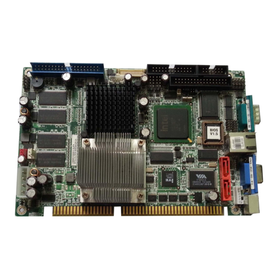
Half-Size ISA CPU Card with Intel Pentium M/ Celeron M at 400MHz FSB, LVDS/CRT for Dual Display, LAN, SATA with RAID, USB2.0
Brand:
IEI Technology
| Category:
Motherboard
| Size: 0.18 MB
Table of Contents
Quick Installation Guide
1
Specifications
2
Ordering Information
3
Jumpers Setting and Connectors
4
Advertisement
Related Products
IEI Technology IMB-G41A
IEI Technology IMBA-9454ISA
IEI Technology IMB-X63 Series
IEI Technology IMBA-H810
IEI Technology IBM-Q670
IEI Technology IMBA-Q870-i2
IEI Technology IMBA-BDE-1548-R10
IEI Technology IEM-DB-7S-RS
IEI Technology IQ7-US15W
IEI Technology IMBA-G412ISA-R20
IEI Technology Categories
Motherboard
Touch Panel
Computer Hardware
Single board computers
Desktop
More IEI Technology Manuals
Login
Sign In
OR
Sign in with Facebook
Sign in with Google
Upload manual
Upload from disk
Upload from URL