Table of Contents
Advertisement
Quick Links
- 1 Tl 6.5 Front Panel Controls
- 2 Back Panel Connections and Controls
- 3 Connecting the Tl 6.5 to a Home Theater System
- 4 Using the Tl 6.5 to Trigger Other Devices
- 5 Operating Modes and Factory Default Settings
- 6 Quick Reference: Special Programming Functions
- 7 Tl-6.5 Specifications
- Download this manual
Advertisement
Table of Contents

Related Manuals for VTL TL6.5


Summary of Contents for VTL TL6.5
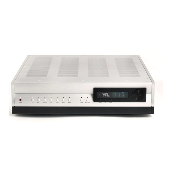
- Page 1 TL6.5 Signature Line Stage Preamplifier O w n e r ’ s M a n u a l...
- Page 2 VTL. Version History: Version 2.2 November, 2007 Part Number: OM-6.5 Copyright © 2008 by VTL Amplifiers Inc. All rights reserved. 4774 Murrieta Street, Suite 10 Chino, CA 91710, USA Phone 909.627.5944 • Fax 909.627.6988 Email: mail@vtl.com • http://www.vtl.com/...
-
Page 4: Table Of Contents
The Remote Control Hand-held Unit ........................12 Fitting the Batteries to the Remote Control..................... 13 Voltage Setting................................. 14 Power Source for the VTL TL 6.5 Preamplifier ...................... 14 Connecting the Preamplifier to your system ......................15 Connecting to a Turntable ..........................15 Select and Connect Source Components...................... - Page 5 Changing the Main, Output stage and Power Supply Protection Fuses..............43 Cleaning ................................... 44 Troubleshooting ............................... 45 ..................................48 CHAPTER 5 TL-6.5 S ............................... 48 PECIFICATIONS ..................................49 CHAPTER 6 ................................... 49 ARRANTY ..................................51 APPENDIX Warranty Registration.............................. 51 Service Notes ................................51 TL6.5 Preamplifier Owner’s Manual...
-
Page 6: Chapter 1
The TL 6.5 Preamplifier truly represents a fresh breakthrough in furthering the refinement of the VTL sound, and the ability of the new TL 6.5 to articulate and present the listener with a broad, cohesive picture of the total musical soundscape in a dynamic, nimble, full range sound gives it the distinction it bears as our Signature Preamplifier. -
Page 7: Symbol Conventions Used In This Guide
The VTL team is proud that you have selected our Signature preamplifier as a new member of your home audio system. This preamplifier is designed to give you the convenience and... -
Page 8: Electrical Safety Notice
Warning – To avoid risk of failure due to overheating, do not stack components The TL 6.5 chassis emits heat and needs proper ventilation to ensure long operational life. Under no circumstances should the TL6.5 be stacked on top of any other unit. -
Page 9: Servicing
Ensure that the TL6.5 is installed in a location that is stable and well ventilated. If the preamplifier is placed in a built-in installation, ensure that there is adequate room for air to flow through the ventilation openings. Allow at least 3 - 5 inches clearance on the top and around the sides of each chassis of the preamplifier. - Page 10 VTL unit. Do not touch the tubes after the TL 6.5 is turned on. The tubes can get very hot while the TL 6.5 is operating. Turn off the TL 6.5 and allow the tubes to cool down before attempting to work with the tubes.
-
Page 11: Chapter 2
Quick Start As the proud owner of this new VTL TL 6.5 Signature preamplifier, you are probably eager at this moment to connect the new preamplifier into your system and hear what TL6.5 Preamplifier Owner’s Manual... - Page 12 Step 5. Turn on the TL 6.5 Preamplifier Locate the Power Rocker switch at the back of the unit. Turn the switch to the “on” position. You should see two blue “--“ displayed in the unit’s Numeric Display window. TL6.5 Preamplifier Owner’s Manual...
-
Page 13: Tl 6.5 Front Panel Controls
Step 6. Turn on your Source component Step 7. Turn on your Power Amplifier(s) Step 8. Wait for the TL6.5 to finish warmup After the TL 6.5’s warm-up countdown is completed, the Power on LED turns to a steady blue indicating that the unit is now ready to play. - Page 14 5. The display window contains the group of three main operational buttons and display LEDs, the numeric display, and the infra red remote receiver, which enables the TL6.5 Preamplifier Owner’s Manual...
- Page 15 When in volume control mode the control knob changes the loudness level of the output from your speaker system. Turning the knob clockwise increases the volume level, and turning the knob counter-clockwise decrease s the volume level. TL6.5 Preamplifier Owner’s Manual...
-
Page 16: The Preamplifier's Back Panel
TL 6.5, including CD, DVD/SACD, and Phono/Aux 1 3 single-ended RCA inputs Aux 2, and Tuner and Aux 3 2 pairs of single ended RCA Tape inputs The RCA and XLR Output Jacks. TL6.5 Preamplifier Owner’s Manual... -
Page 17: The Remote Control Hand-Held Unit
Power the preamplifier on and off. This is a toggle control, which changes the state from one to the other each time it is pressed. • Set the left and right channel balance offset • Select any of the 8 inputs directly TL6.5 Preamplifier Owner’s Manual... -
Page 18: Fitting The Batteries To The Remote Control
There is also a separate RS-232 port on the back of the preamplifier’s chassis that can accept any of the commands required to control the preamplifier remotely, and outputs messages as the front panel controls on the TL6.5 are changed. This RS-232 port is or for a central remote command system. -
Page 19: Voltage Setting
Voltage Setting Your VTL TL 6.5 preamplifier has already been set to the correct voltage for your country where you made your purchase, and the voltage setting is marked on the Serial Number Badge located on the back panel of your TL 6.5. -
Page 20: Connecting The Preamplifier To Your System
Phono/Aux 1 input channel of the preamplifier. Connect the Tape input channels to the preamplifier To take advantage of the Tape Monitor capability of the preamplifier, connect the Tape In on the tape deck(s) to either of TL6.5 Preamplifier Owner’s Manual... -
Page 21: Connecting A Second Pair Of Amplifiers
Although the preamplifier can easily drive extremely low impedances, when connecting more than one pair of amplifiers in parallel it is advised that you are aware of the different input impedances, sensitivities and resultant input impedance. If you have any questions TL6.5 Preamplifier Owner’s Manual... -
Page 22: Connecting The Tl 6.5 To A Home Theater System
VTL factory service department. Connecting the TL 6.5 to a Home Theater System Your VTL TL 6.5 preamplifier is designed to work in conjunction with both conventional two-channel and home theater systems. If you have both systems set... - Page 23 TL-6.5. The connector only plugs in one way, so it is polarized. Your authorized VTL dealer can supply the connector, and make up the correct cable for triggering other devices in your system (usually power amplifier(s)), which will be a custom length, and will include the correct connector for the device to be triggered.
-
Page 24: Chapter 3
AC supply, with the AC ground securely connected to the ground of the AC supply. Contact your VTL dealer if the unit still will not power up after these checks have been performed. -
Page 25: Ground Loop Hum
Ground Loop Hum If you get a ground loop hum from your stereo system after installation and power up you should immediately turn off the TL 6.5 and consult your VTL dealer or the VTL factory. Caution: Under no circumstances should you attempt to lift... -
Page 26: Using The Preamplifier With The Remote Control
If you use a tape deck that gives you the capability of monitoring the recording, i.e. listening to the recording while it is taking place, you can use the TL 6.5’s Tape Loop function to take advantage of this feature. Connect the tape’s input and output cables to the TL 6.5’s Tape Out TL6.5 Preamplifier Owner’s Manual... -
Page 27: Operating Modes And Factory Default Settings
Channel Balance Not selected, no imbalance Bal LED off Unity Gain input Not set None Tape Monitor Not set Mon/Proc LED off Suppress Out of Balance display Not set None Programming Lock Out Not set None TL6.5 Preamplifier Owner’s Manual... -
Page 28: Quick Reference: Special Programming Functions
Release the input button volume of the system will not change. to complete the setting. To remove Input level Offset, hold the input button down and turn the volume control counterclockwise until numeric display indicates TL6.5 Preamplifier Owner’s Manual... -
Page 29: Led Indications
During Power up sequence, these LEDs will blink RED if that trigger (either inputs 1 and 2) is programmed, else no LED is lit. During trigger sequence, blink red until trigger activates, then steady red while other triggers activate, then off after all programmed triggers activated. TL6.5 Preamplifier Owner’s Manual... - Page 30 After power up and trigger sequence, LED off for Phase correct and red for Phase inverting. Channel Balance LED During Power up and trigger sequence, no LED. After power up and trigger sequence, LED will light blue if channel balance function is selected. TL6.5 Preamplifier Owner’s Manual...
-
Page 31: Programming The Preamplifier's Function Controls
The unit is completely off and cannot be turned on via any front panel or remote command. 2. Stand-by Mode Unit is left in standby and waiting power up command when not operated. No circuits are running, except logic circuit to power control microprocessor. TL6.5 Preamplifier Owner’s Manual... - Page 32 User input: During the preamp’s power up cycle, the user presses front panel Power On button while holding Mon/Proc button down. Addressable through RS-232 port also – see specific section for command structure. Indication: No indication. TL6.5 Preamplifier Owner’s Manual...
- Page 33 Triggers that are programmed off will not light trigger LEDs. Trigger outputs that are programmed will blink input LEDs red during power-up cycle before turning on each selected trigger. Countdown begins again at 90 seconds after each TL6.5 Preamplifier Owner’s Manual...
- Page 34 User input: While unit is powered up user presses the selected input button on the front panel while holding down the Mute button. Addressable through RS-232 port also – see specific section for command structure. TL6.5 Preamplifier Owner’s Manual...
- Page 35 (typically multi-channel surround sound) will control gain to the same channels that the preamplifier is controlling in the two-channel system configuration. In this case, to achieve proper system volume balance and make gain adjustment more TL6.5 Preamplifier Owner’s Manual...
- Page 36 Mute mode. If there is no reaction then the input is not selected and the previously selected input stays selected. 13. User toggles between play and mute modes (Remote or Front Panel) TL6.5 Preamplifier Owner’s Manual...
- Page 37 If unit is in Mute mode then volume up changes unit to Play mode, while volume down keeps unit in Mute mode. 14. User changes channel balance (Remote or Front Panel) TL6.5 Preamplifier Owner’s Manual...
- Page 38 (for leftward balance) or on right (for rightward balance). The balance display remains unchanged for 2 seconds after the Balance button is released, and the display returns to indicating the volume setting. TL6.5 Preamplifier Owner’s Manual...
- Page 39 If the user wants to be able to listen to the recording as it is being made on such an equipped tape deck then the monitor function is used. The selected input being recorded will still be routed to the record output (which is connected to the input on TL6.5 Preamplifier Owner’s Manual...
- Page 40 Last used input selection, phase, channel balance unity gain processor loop settings, countdown and balance suppression are all saved in memory for next power-up. 22. User re-powers after power down command (Front panel or remote wand only) TL6.5 Preamplifier Owner’s Manual...
-
Page 41: Using The Preamplifier With Rs232 Control
‘event generation’, to keep other connected components in synch with the TL-6.5. Control functions and information returned are accessed through the rear RS-232 port via a standard DB9 male female connector cable and standard ASCII text strings using TL6.5 Preamplifier Owner’s Manual... - Page 42 {} meaning required parameters and [] meaning optional parameters. For systems without a return button the amplifier’s microprocessor recognizes /C as a carriage return, and /R as a return. The input and output buffers of the TL6.5 can hold a maximum of 256 bytes at one time.
- Page 43 Returns current offset settings for equalize volume between selected input, in degree of offset, for inputs. example: >OFFSET -01 >UNITY For toggling between unity If queried returns current unity inputs, gain settings and normal [input][ON|OFF] example: >UNITY GAIN: TL6.5 Preamplifier Owner’s Manual...
- Page 44 >LOCKOUT ON for locked front panel >VTL Returns factory contact Contact VTL: info Email: mail@vtl.com Tel. 909-627-5944 Fax. 909-627-6988 >VERSION Returns the version Installed version of the software: number of the software. TL6.5 Preamplifier Owner’s Manual...
-
Page 45: Powering The System Off
>Version 050529 Powering the system off You may keep your VTL preamplifier and your source components on permanently if you prefer to keep them warm. If you prefer to keep all your equipment off when not in use then it is best to follow the correct turn off sequence to avoid power off thumps through the system. -
Page 46: Chapter 4
VTL preamplifier Break In Period Your VTL TL6.5 is a hybrid product designed to give you the continued optimum performance over an extremely long time period. Initially the tubes and circuits will require a burn-in period to reach maximum performance. During the first 100 hours of usage the preamplifier will undergo several improvements in sound. - Page 47 Re-tubing the VTL TL 6.5 requires removal of some or all of the covers, which can expose potentially lethal voltages. Be sure to only touch the tubes themselves, and do not allow any part of your body or hanging jewelry to come into contact with any part of the circuit inside the unit.
-
Page 48: Changing The Main, Output Stage And Power Supply Protection Fuses
The fuse cap should spring out from its housing with the fuse held inside the cap. Take the fuse out and replace it with a new one, and insert the fuse cap back into the holder, pushing it TL6.5 Preamplifier Owner’s Manual... -
Page 49: Cleaning
VTL factory for service. Cleaning Your VTL preamplifier should be dusted occasionally with a damp non-abrasive cloth. Do not use any solvents for cleaning the front panel, as this can damage the lettering and the finish. It is recommended that you use a contact cleaner such as Pro-Gold on the input... -
Page 50: Troubleshooting
Factory for a solution to this problem. Note that in either case there is no damage being done to your VTL preamplifier while it is being used in these states, and you can continue to safely use the preamplifier until a solution is reached. - Page 51 TV wire by means of a cable ground lifting transformer available from most electronics stores. If the problem still persists contact your VTL authorized dealer or the VTL factory service department.
- Page 52 If the remote control unit is still not functioning properly, contact your VTL authorized dealer or the VTL factory service department.
-
Page 53: Chapter 5
30 Volts 10Hz – 200kHz into 600 ohms at 1%THD Channel Separation > 100 dB @ 1KHz (>80 dB @ 20kHz) Power Consumption 150 Watts 50 lbs (22.72 Kg) Fully packed in one box Weight Unpacked weight: 45 lbs TL6.5 Preamplifier Owner’s Manual... -
Page 54: Chapter 6
This must be shipped to VTL Amplifiers Inc via insured freight at the customer's own expense. Charges for unauthorized service and transportation costs... - Page 55 USA may not be registered for warranty with the factory in the USA, but may only be registered with the VTL distributor in the country of purchase. In the case of returns from outside the USA, the owner of the product returned is...
-
Page 56: Appendix
A P P E N D I X Warranty Registration Warranty registration for VTL products is valid in the USA only. International VTL customers should consult their local VTL dealer regarding product registration and warranty procedures. To obtain valid US warranty service, please fill out the enclosed VTL Warranty...
Need help?
Do you have a question about the TL6.5 and is the answer not in the manual?
Questions and answers