Table of Contents
Advertisement
Advertisement
Table of Contents

Related Manuals for VTL TL5.5 Series II Signature


Summary of Contents for VTL TL5.5 Series II Signature
- Page 1 TL5.5 Series II Signature Preamplifier O w n e r ’ s M a n u a l...
- Page 2 VTL. Version History: Version 2.0 May 19, 2010 Part Number: OM-6.5 Copyright © 2011 by VTL Amplifiers Inc. All rights reserved. 4774 Murrieta Street, Suite 10 Chino, CA 91710, USA Phone 909.627.5944 • Fax 909.627.6988 Email: mail@vtl.com • http://www.vtl.com/...
-
Page 4: Table Of Contents
The Remote Control Hand-held Unit ........................11 Fitting the Batteries to the Remote Control..................... 12 Voltage Setting ................................ 13 Power Source for the VTL TL-5.5 Preamplifier ..................... 13 Connecting the Preamplifier to your system ......................14 Connecting to a Turntable ..........................14 Select and Connect Source Components...................... - Page 5 Changing the Main Fuses............................44 Internal View of TL5.5 II Line Stage ........................45 Internal View of TL5.5 II Line and Phono Stage ....................45 Internal View of TL5.5 II Phono Stage ........................46 Cleaning..................................46 Troubleshooting ............................... 46 .................................... 49 chapter 5 TL-5.5II Specifications ..............................
-
Page 6: Chapter 1
(and therefore dynamic headroom) always yields superior sound in dynamic musical passages. Ease of installation is another primary benefit with preamplifiers. The VTL TL5.5 Signature Line preamplifier is both a fully active line level preamplifier and a complete source control center in one package, and it offers complete predictability of performance with little or no change of response in a wide range of systems and environments. -
Page 7: Symbol Conventions Used In This Guide
TL-5.5 is a truly fine addition to any system. The VTL team is proud that you have selected our Signature preamplifier as a new member of your home audio system. This preamplifier is designed to give you the convenience and... -
Page 8: Water And Moisture
Servicing Do not attempt to service the TL5.5 beyond the procedures described in this manual. For all other service and questions, please contact your authorized VTL dealer or the factory. TL5.5 SERIES II Preamplifier Owner’s Manual... -
Page 9: Operational Warnings
Do not attempt to disassemble the TL5.5 chassis or remove any covers from the unit. Always consult with your VTL authorized dealer or the VTL factory before attempting any service work on any VTL unit. Do not touch the tubes after the TL5.5 is turned on. The tubes can get very hot while the TL5.5 is operating. -
Page 10: Chapter 2
There should be no rattles inside either the preamplifier chassis or remote control units. Look through the vent slots and check to see that the tubes appear properly seated in their sockets. Contact your VTL dealer immediately if physical damage is detected. -
Page 11: Quick Start
Quick Start As the proud owner of this new VTL TL5.5 Signature preamplifier, you are probably eager at this moment to connect the new preamplifier into your system and hear what it sounds like. This section is a quick setup-up guide to help you get started in the shortest time possible. -
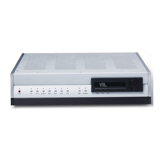
Page 12: Tl5.5 Front Panel Controls
Step 5. Turn on the TL5.5 Preamplifier Locate the Power Rocker switch at the back of the unit. Turn the switch to the “on” position. You should see two blue “--“ displayed in the unit’s Numeric Display window. Locate the red Power button on the front panel of the unit located on the far left side of the Preamplifier. - Page 13 You can operate the various controls and buttons from the front panel to access the full functionality of this unit, and the operational functionality can also be accessed via the remote control. The indication LEDs show the various operating modes of the unit. 1.
- Page 14 5. The display window contains the group of three main operational buttons and display LEDs, the numeric display, and the infra-red remote receiver, which enables the transmission of signal from the remote hand-held unit to be received by the preamplifier. Keep this window clear from any obstruction and out of direct light to allow maximum signal transmission from the remote wand.
-
Page 15: The Preamplifier's Back Panel
• When in volume control mode the control knob changes the loudness level of the output from your speaker system. Turning the knob clockwise increases the volume level, and turning the knob counter-clockwise decrease s the volume level. The Preamplifier’s Back Panel From the back panel of the chassis you can access the power connector, trigger outputs, RS-232 port, AC fuse, and the serial number and power consumption of the unit, as well as all of the audio inputs and outputs. -
Page 16: The Remote Control Hand-Held Unit
1 pairs single ended and 1 pair balanced Main Outputs 1 pair of fixed single ended buffered record out The Remote Control Hand-held Unit Fig 3. Remote Control Unit The Remote Control hand held unit supplied with this preamplifier allows the user to perform the following functions: •... -
Page 17: Fitting The Batteries To The Remote Control
• Set the preamp between phase inverting and phase correct mode by pressing the phase button. This is a toggle control, which changes the state from one to the other each time it is pressed. • Increase/decrease the volume by pressing the up and down buttons respectively on the remote control hand-held unit. -
Page 18: Voltage Setting
VTL dealer. Voltage Setting Your VTL TL5.5 preamplifier has already been set to the correct voltage for your country where you made your purchase, and the voltage setting is marked on the Serial Number Badge located on the back panel of your TL5.5. -
Page 19: Connecting The Preamplifier To Your System
Connecting the Preamplifier to your system Connecting to a Turntable You can connect your TL-5.5 preamplifier to the turntable if the unit comes with the internal optional phono stage. Please check the preamplifier by looking down through the slots on the top cover and see if there is a PC board mounted on the left side of the bottom chassis. -
Page 20: Connecting To A Turntable
TL5.5 preamplifier is 6dB lower in gain than the balanced output. If you have any questions about this then you should contact either your dealer or the manufacturers of your amplifiers, or contact the VTL factory customer service department. -
Page 21: Connecting The Tl5.5 To A Home Theater System
Connecting the TL5.5 to a Home Theater System Your VTL TL5.5 preamplifier is designed to work in conjunction with both conventional two-channel and home theater systems. If you have both systems set up so that your front speakers are used for your audio as well as home theater systems, then connect the external surround processor front left and right main outputs to any of the preamplifier’s inputs. - Page 22 Your authorized VTL dealer can supply the connector, and make up the correct cable for triggering other devices in your system (usually power amplifier(s)), which will be a custom length, and will include the correct connector for the device to be triggered.
-
Page 23: Chapter 3
AC supply, with the AC ground securely connected to the ground of the AC supply. Contact your VTL dealer if the unit still will not power up after these checks have been performed. -
Page 24: Ground Loop Hum
“Operating modes and LED Indications”: Ground Loop Hum If you get a ground loop hum from your stereo system after installation and power up you should immediately turn off the TL5.5 and consult your VTL dealer or the VTL factory. Caution:... -
Page 25: Using The Tape Loop To Monitor Recordings
3. Use the remote control wand’s source buttons to select the desired source. 4. Use the remote control’s volume button to adjust the desired playing level. Increase the volume by pressing the up button on the remote control., and decrease the volume by pressing the down button on the remote control. -
Page 26: Connecting To The Turntable
If your TL-5.5 Series II Preamplifier is equipped with the optional internal phono stage, you can use the phono stage with either MM or MC cartridge. The VTL factory standardly configures the TL-5.5 II phono stage to work with a MC cartridge and with the... -
Page 27: Quick Reference: Special Programming Functions
Tape Monitor Not set Mon/Proc LED off Suppress Out of Balance display Not set None Programming Lock Out Not set None Quick Reference: Special Programming Functions Function Programming Sequence Enable Trigger Output: During the power up 90 to 0 countdown To set up to 2 Trigger sequence, user holds down any of Input 1 thru 2 outputs to remotely turn on your system... -
Page 28: Led Indications
so that when an input is selected the overall The numeric display will now indicate the Offset volume of the system will not change. value that you wish to set. Release the input button to complete the setting. To remove Input level Offset, hold the input button down and turn the volume control counterclockwise until numeric display indicates View Input Level Offset: (In Lock Out... - Page 29 During Power up sequence, these LEDs will blink RED if that trigger (either inputs 1 and 2) is programmed, else no LED is lit. During trigger sequence, blink red until trigger activates, then steady red while other triggers activate, then off after all programmed triggers activated. After trigger sequence, LED will turn OFF if not selected as input.
-
Page 30: Programming The Preamplifier's Function Controls
Channel Balance LED During Power up and trigger sequence, no LED. After power up and trigger sequence, LED will light blue if channel balance function is selected. Mute LED When the unit is in mute the LED light blinks steadily. When the unit is in normal operating mode, the mute LED light is off. - Page 31 Status: The unit is completely off and cannot be turned on via any front panel or remote command. 2. Stand-by Mode Unit is left in standby and waiting power up command when not operated. No circuits are running, except logic circuit to power control microprocessor. User input: AC power is connected to the preampand rear rocker switch is switched to ON position.
- Page 32 User input: During the preamp’s power up cycle, the user presses front panel Power On button while holding Mon/Proc button down. Addressable through RS-232 port also – see specific section for command structure. Indication: No indication. Status: Unit allows all programming functions (Triggers, trigger timing, Unity gain, input mode, input disable or enable, and input offset) while unlocked.
- Page 33 Indication: Except for setup via the RS-232 port, the numeric display changes from incremental timer count (if not suppressed) to steady numerical display indicating time at which trigger output will turn on after power-up cycle is completed. Triggers that are programmed off will not light trigger LEDs.
- Page 34 User input: While unit is powered up user presses the selected input button on the front panel while holding down the Mute button. Addressable through RS-232 port also – see specific section for command structure. Indication: The blanked input LED goes out, and no input is set until any other input is selected, and thereafter the blanked input is unable to be selected until it is re-enabled.
- Page 35 Unity gain is used when there is another unit in the system that in an alternative system configuration (typically multi-channel surround sound) will control gain to the same channels that the preamplifier is controlling in the two-channel system configuration. In this case, to achieve proper system volume balance and make gain adjustment more predictable it is desirable to avoid the need to use two volume controls, and the two channel preamplifier is set to pass signal through to the amplifiers its is connected to without gain or attenuation.
- Page 36 then the unit goes into Mute mode. If there is no reaction then the input is not selected and the previously selected input stays selected. 13. User toggles between play and mute modes (Remote or Front Panel) Mute is used to instantly bring the output of the preamplifier to zero level. User input: User presses the mute button on the front panel or the mute button on the remote control, or sends a discrete mute or unmute signal...
- Page 37 Status: Volume level is changed and the display increments or decrements sequentially to the new volume setting. If unit is in Mute mode then volume up changes unit to Play mode, while volume down keeps unit in Mute mode. 14. User changes channel balance (Remote or Front Panel) Changing channel balance is sometimes required where there is uneven signal from left to right, (or vice versa), or an uneven room acoustic, requiring a compensating adjustment to equalize volume level from both channels.
- Page 38 the volume display reverts to displaying volume, the directional bar is displayed next to the volume level indication in whichever direction the balance is out of balance, either on left (for leftward balance) or on right (for rightward balance). The balance display remains unchanged for 2 seconds after the Balance button is released, and the display returns to indicating the volume setting.
- Page 39 Status: Output volume level drops directly to volume level of 20 (including offset.) If the volume level is less than 20, or if the unit is in Mute mode, pressing the Fade button will not change the level. 19. User monitors input while recording (any input) (Front Panel only) If the user wants to be able to listen to the recording as it is being made on such an equipped tape deck then the monitor function is used.
-
Page 40: Using The Preamplifier With Rs232 Control
Status: The unit immediately begins power down and releases output relays to closed position. Last used input selection, phase, channel balance unity gain processor loop settings, countdown and balance suppression are all saved in memory for next power-up. 22. User re-powers after power down command (Front panel or remote wand only) User changes mind on powering down, or powers down accidentally, and does not wish to wait for 90 second power up timer in order to be able to continue operation. - Page 41 The preamplifier also communicates via the RS-232 port any changes made via the front panel or remote wand, using what is called ‘event generation’, to keep other connected components in synch with the TL-5.5. Control functions and information returned are accessed through the rear RS-232 port via a standard DB9 male female connector cable and standard ASCII text strings using pre-defined commands as listed below in the summary of all the control functions that can be performed on the front panel and the expected results on the RS-232 port.
- Page 42 > HELP, LOCKOUT [ON|OFF], MUTE [ON|OFF], OFFSET [[+|-]n], PHASE [0|180], > POWER [ON|OFF], STATUS, TRIGGER, UNITY [input][ON|OFF], VERSION, > VOLUME [[+|-]n], VTL >STATUS For querying the status Returns current status as set, for of the preamplifier example: >STATUS: POWER ON,...
- Page 43 X1|PHAUX2|A input. UX3|TUN|AUX 4|AUX5|TAPE} >BALANCE For changing the channel Changes the channel balance in single balance, or going directly [{L|R|+|-}n] step increments (or decrements) and to a particular channel outputs the new balance setting to the balance setting. RS-232 port >PHASE [0|180] For querying or setting Returns current phase setting.
-
Page 44: Powering The System Off
>Version 072109 Powering the system off You may keep your VTL preamplifier and your source components on permanently if you prefer to keep them warm. If you prefer to keep all your equipment off when not in use then it is best to follow the correct turn off sequence to avoid power off thumps through the system. - Page 45 2. Allow a short time (15 - 20 seconds) for the amplifier(s) to power down before you turn the preamplifier off. If the trigger function is being used, powering the preamplifier off will automatically turn off the power amplifier(s). 3. Turn the source components off, if you prefer to keep these off when not in use. TL5.5 SERIES II Preamplifier Owner’s Manual...
-
Page 46: Chapter 4
VTL preamplifier Break In Period Your VTL TL5.5 SERIES II preamplifier is a pure tube product designed to give you the continued optimum performance over an extremely long time period. Initially the tubes and circuits will require a burn-in period to reach maximum performance. During the first 100 hours of usage the preamplifier will undergo several improvements in sound. - Page 47 PREAMPLIFIER WITH YOUR FINGERS OR WITH ANY METALLIC OBJECT, UNTIL AFTER THE UNIT HAS BEEN SAFELY DISCHARGED. VTL preamplifiers can store energy in the power supplies long after they have been turned off, and incorrectly discharging the unit can damage the circuits, which will NOT be covered under the warranty.
- Page 48 tube pins, gently and in small amounts rotate and rock the tube with your fingers to loosen it from its socket until its pins are completely disengaged from the socket. Take the tube out of the unit. 1. Plugging in a new tube: Hold onto the upper portion of the tube towards its tip.
-
Page 49: Changing The Main Fuses
TL5.5. If you have problems locating the correct fuse contact your VTL dealer or the VTL factory service department. TL5.5 SERIES II Preamplifier Owner’s Manual... -
Page 50: Internal View Of Tl5.5 Ii Line Stage
Internal View of TL5.5 II Line Stage Internal View of TL5.5 II Line and Phono Stage TL5.5 SERIES II Preamplifier Owner’s Manual... -
Page 51: Internal View Of Tl5.5 Ii Phono Stage
Consult your dealer or the VTL factory for service. Cleaning Your VTL preamplifier should be dusted occasionally with a damp non-abrasive cloth. Do not use any solvents for cleaning the front panel, as this can damage the lettering and the finish. - Page 52 Factory for a solution to this problem. Note that in either case there is no damage being done to your VTL preamplifier while it is being used in these states, and you can continue to safely use the preamplifier until a solution is reached.
- Page 53 If the remote control unit is still not functioning properly, contact your VTL authorized dealer or the VTL factory service department.
-
Page 54: Chapter 5
C H A P T E R TL-5.5II Specifications Vacuum Tube Complement 2 x 12AU7, 4 x 12AT7 (line stage) 2 pair balanced/XLR or RCA single-ended Inputs 6 pairs single-ended/RCA 1 pair balanced out 1 pair single-ended RCA out Outputs 1 pair single-ended RCA buffered Record Out Power Source Select... - Page 55 TL5.5 II Phono Stage Tube Complement 2x12AX7, 2x12AT7 2x12AT7, 2x12AX7, 2x12AU7 Load 47K ohm Selectable 100 ohm, 220 ohm, 470 ohm, 1K ohm, 47K ohm Gain 40 dB Selectable 54dB, 60dB, 66dB TL5.5 SERIES II Preamplifier Owner’s Manual...
-
Page 56: Chapter 6
This must be shipped to VTL Amplifiers Inc via insured freight at the customer's own expense. Charges for unauthorized service and transportation costs... - Page 57 USA may not be registered for warranty with the factory in the USA, but may only be registered with the VTL distributor in the country of purchase. In the case of returns from outside the USA, the owner of the product returned is...
-
Page 58: Appendix
A P P E N D I X Warranty Registration Warranty registration for VTL products is valid in the USA only. International VTL customers should consult their local VTL dealer regarding product registration and warranty procedures. To obtain valid US warranty service, please fill out the enclosed VTL Warranty...
Need help?
Do you have a question about the TL5.5 Series II Signature and is the answer not in the manual?
Questions and answers