Advantech SmartMotion ST355 User Manual
Twin cellular module router
Hide thumbs
Also See for SmartMotion ST355:
- User manual (51 pages) ,
- Hardware manual (48 pages) ,
- Start manual (20 pages)
Table of Contents
Advertisement
Quick Links
Advertisement
Table of Contents

Related Manuals for Advantech SmartMotion ST355


Summary of Contents for Advantech SmartMotion ST355
- Page 1 Twin Cellular Module Router SmartMotion ST355 USER’S MANUAL...
- Page 2 2016 Advantech B+B SmartWorx s.r.o.. No part of this publication may be reproduced or transmitted in any form or by any means, electronic or mechanical, including photography, recording, or any information storage and retrieval system without written consent. Information in this manual is subject to change without notice, and does not represent a commitment on the part of Advantech B+B SmartWorx.
- Page 3 GPL licence Source codes under GPL licence are available free of charge by sending an email to: cellularsales@advantech-bb.com. Advantech B+B SmartWorx s.r.o., Sokolska 71, 562 04 Usti nad Orlici, Czech Republic Manual Rev. 1 released in CZ, April 15, 2016...
-
Page 4: Table Of Contents
CONTENTS Contents 1 Safety Instruction 2 WEEE directive 3 Router Description 3.1 Usage of the Router ....... . . 4 Contents of Package 5 Router Design 5.1 Router versions... - Page 5 CONTENTS 7.3 Type tests and environmental conditions ..... . 7.4 Technical parameters of cellular modules ..... 7.4.1 Technical parameters of the first cellular module .
- Page 6 LIST OF FIGURES List of Figures Access to the Internet from LAN ......Backed up access to the Internet .
- Page 7 LIST OF TABLES List of Tables Router versions ........Delivery identification .
-
Page 8: Safety Instruction
1. SAFETY INSTRUCTION 1. Safety Instruction Please, observe the following instructions: The router must be used in compliance with all applicable international and national laws and in compliance with any special restrictions regulating the utilization of the router in prescribed applications and environments. To prevent possible injury and damage to appliances and to ensure compliance with all relevant provisions, use only the original accessories. -
Page 9: Weee Directive
2. WEEE DIRECTIVE 2. Product Disposal Instructions The WEEE (Waste Electrical and Electronic Equipment: 2002/96/EC) directive has been introduced to ensure that electrical/electronic products are recycled using the best available recovery techniques to minimize the impact on the environment. This product contains high quality materials and components which can be recycled. -
Page 10: Router Description
3. ROUTER DESCRIPTION 3. Router Description SmartMotion ST355 is an industrial cellular router intended for wireless communication in mobile networks that make use of LTE, HSPA+, UMTS, CDMA, EDGE or GPRS technol- ogy. The router is equipped with two independent cellular modules for backed up communi- cation. -
Page 11: Usage Of The Router
3. ROUTER DESCRIPTION Examples of possible applications mobile office telemetric fleet management remote monitoring security system vending and dispatcher machines telematic 3.1 Usage of the Router The router is primarily intended for these four basic situations: I. Access to the Internet from LAN Figure 1: Access to the Internet from LAN... -
Page 12: Backed Up Access To The Internet
3. ROUTER DESCRIPTION II. Backed up access to the Internet (from LAN) Figure 2: Backed up access to the Internet III. Secure networks interconnection or using VPN Figure 3: Using VPN tunnel... -
Page 13: Serial Gateway
3. ROUTER DESCRIPTION IV. Serial Gateway Figure 4: Serial Gateway... -
Page 14: Contents Of Package
4. CONTENTS OF PACKAGE 4. Contents of Package Basic delivered set of router includes: router, power supply, crossover UTP cable, up to three external antennas, loose power and I/O connector (+8 pins clip for the DIN rail, paper start guide. Figure 5: Contents of package Temperature range for power supply is reduced to 0 C to +40 C! These pins are designed for cables with a diameter from 0.2 to 0.8 mm... -
Page 15: Router Design
5. Router Design 5.1 Router versions SmartMotion ST355 router is supplied in the following versions (see table below). All ver- sions are available in a metal box. All versions are available with PoE PD (Power over Ethernet – powered device) so you can power the router from both ETH0 and ETH1 interfaces, or with PoE PSE (power source equipment) so you can power other devices by the router. -
Page 16: Order Codes
5. ROUTER DESIGN 5.3 Order codes Order codes overview is shown in the table below. Product Name Order code Features – interfaces ST355 ST3520x0yz 2x LTE module (1x LTE 450 MHz), 2x ETH, 1x USB, 2x BI, 1x BO, 1x microSD reader, 4x SIM reader ST355 ST3521x0yz 2x LTE module (1x LTE 450 MHz), 2x ETH, 1x USB, 2x BI,... -
Page 17: Examples Of Order Code
5. ROUTER DESIGN Examples of complete order code: Order code Features – interfaces Power supply SR35508020 2x LTE module (1x LTE 450 MHz), 2x ETH, 1x USB, metal none 2x BI, 1x BO, 1x microSD reader, 4x SIM reader, PoE PSE SR35519020 2x LTE module (1x LTE 450 MHz), 2x ETH, 1x USB, metal... -
Page 18: Basic Dimensions Of The Router Box
5. ROUTER DESIGN 5.4 Basic dimensions of the router box Figure 9: Basic dimensions of the router box 5.5 Mounting recommendations Possibility to be put on a work surface, DIN rail EN 60715 with included clip CPD3 (or CKD2 for metal version). For the most of applications with a built-in router in a switch board it is possible to recognize two kinds of environments: No public and industry environment of low voltage with high interference,... -
Page 19: Removing From The Din Rail
5. ROUTER DESIGN – With data cables they mustn’t carry cables with reticular tension 230 V/50 Hz. Sufficient space must be left before individual connectors for handling of cables, For correct function of the router we recommend to use in the switch-board earth-bonding distribution frame for grounding of power supply of router, data cables and antenna. -
Page 20: Description Of The Rear Panel
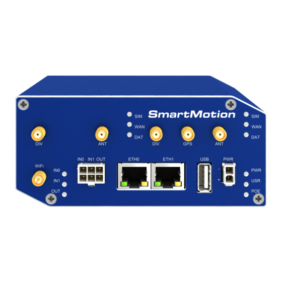
5. ROUTER DESIGN 5.7 Description of the rear panel The rear panel contains only four SIM cards readers (SIM1, SIM2, SIM3 and SIM4), mi- croSD card reader (SD) and RST button used to restore default configuration and reboot the SmartMotion router. 5.8 Description of the front panel On the front panel is the following: Caption... -
Page 21: Status Indication
5. ROUTER DESIGN 5.8.1 Status indication About router status inform nine LED indicators on the front panel. Each ETH port has two additional LEDs that provide information about port status. Caption Color State Description Green Blinking Router is ready Starting of the router Fast blinking Updating firmware Yellow... -
Page 22: Power Connector Pwr
5. ROUTER DESIGN 5.8.2 Power connector PWR Panel socket 2-pin. Pin number Signal mark Description GND(-) Negative pole of DC supply voltage VCC(+) Positive pole of DC supply voltage (+10 to +60 V DC) Table 10: Connection of power connector Figure 13: Power connector Power supply for the router must be between +10 V to +60 V DC supply. -
Page 23: Antenna Connector Ant, Div, Gps And Wifi
5. ROUTER DESIGN 5.8.3 Antenna connector ANT, DIV, GPS and WiFi Main, diversity and GPS antennas are connected to the router using the SMA connector on the front panel. There is also available R-SMA antenna connector through which the additional antenna can be connected, if the router is equipped with WiFi module. -
Page 24: Sim Card Reader
5. ROUTER DESIGN 5.8.4 SIM card reader Four SIM card readers for 3 V and 1.8 V SIM cards are placed on the rear panel of the router. For getting the router to work is necessary to insert an activated SIM card with an un- blocked PIN code. -
Page 25: Ethernet Ports (Eth0 And Eth1)
5. ROUTER DESIGN Changing the microSD card: Use the flat end of a spudger, or your fingernail, to press the microSD card slightly deeper into its slot until you hear a click. After the click, release the card and it will pop out of its slot. Remove the microSD card and push any other microSD card into the slot until it clicks in place. -
Page 26: Power Over Ethernet (Poe)
5. ROUTER DESIGN Crossover UTP cable (Ethernet cable) plug into the RJ45 connector labeled as ETH0 or ETH1 (see figure below). Figure 19: Connection of ethernet cable The insulation strength of Ethernet ports from each other and from the rest of the router (grounding) is dependent on the router version: Router Version Insul. -
Page 27: Poe Pse Usage
5. ROUTER DESIGN The PoE PD parameters can be found in Chapter 7.8. The POE LED on the front panel of the router turns on with the green light on the voltage present in an Ethernet port so the user knows the router can be PoE powered. -
Page 28: Usb Port
5. ROUTER DESIGN 5.8.8 USB Port Panel socket USB-A. Signal mark Description Data flow direction +5 V Positive pole of 5 V DC supply voltage, 0.5 A USB data - USB data signal – negative pole Input/Output USB data + USB data signal –... -
Page 29: Binary Inputs Connection
5. ROUTER DESIGN Binary inputs Characteristics of inputs: logical 0 / 1 Voltage Current Web interface status log. 1 max 0.4 mA log. 0 min 0.7 mA log. 0 type 12 V 2 mA log. 0 max 60 V 7 mA Table 16: Characteristics of inputs The binary input status in the Shell returned via io get bin0 or io get bin1. -
Page 30: Reset
5. ROUTER DESIGN 5.8.10 Reset When PWR LED starts flashing on the front panel, it is possible to restore the default con- figuration of the router by pressing the RST button on the rear panel. After pressing this button the default configuration is restored and then router reboots (green LED will be on). For pressing the RST button could be used a narrow screwdriver. -
Page 31: First Use
6. FIRST USE 6. First Use 6.1 Connecting the router before first use Before putting the router into operation it is necessary to connect all components which are required to run your applications. Don’t forget to insert SIM card. The router can not operate without connected antenna, SIM card and power supply. If the antenna is not connected, router can be damaged. -
Page 32: Start
6. FIRST USE 6.2 Start The router is put into operation when the power supply is connected to this router. By default, the router will automatically start to log on to the default APN. DHCP server will start to assign addresses for devices on the Ethernet port ETH0. Router behavior can be changed via the web interface. -
Page 33: Router Web Interface
6. FIRST USE After successfully entering login information user gains access to the router via his internet browser. Figure 30: Router web interface A detailed description of the router settings via the Web interface can be found in the document Configuration manual for SmartMotion routers. -
Page 34: Technical Parameters
7. TECHNICAL PARAMETERS 7. Technical Parameters 7.1 Basic parameters SmartMotion Router Temperature range Operating -20 C to +60 C Storage -40 C to +85 C Cold start -15 C Data transfers via mobile network are available immediately -20 C Data transfers via mobile network are available approximately in five minutes after the start of the router. -
Page 35: Standards And Regulations
7. TECHNICAL PARAMETERS 7.2 Standards and regulations The router complies with the following standards and regulations. Standards and regulations Telecom and emission ETSI EN 301 511 v9.0.2, ETSI EN 301 908-1 v5.2.1, for the 1st module ETSI EN 301 908-2 v5.2.1, ETSI EN 301 908-13 v5.2.1, ETSI EN 300 328 v1.8.1 Telecom and emission ETSI EN 301 908-1 v6.2.1, ETSI EN 301 908-13 v6.2.1,... -
Page 36: Type Tests And Environmental Conditions
7. TECHNICAL PARAMETERS 7.3 Type tests and environmental conditions Phenomena Test Description Test levels EN 61000-4-2 Enclosure contact 6 kV (crit. A) Enclosure air 8 kV (crit. A) RF field AM IEC 61000-4-3 Enclosure 20 V/m (crit. A) modulated (80 – 2700 MHz) Fast transient EN 61000-4-4 Signal ports... -
Page 37: Technical Parameters Of Cellular Modules
7. TECHNICAL PARAMETERS 7.4 Technical parameters of cellular modules 7.4.1 Technical parameters of the first cellular module Technical parameters of the first cellular module LTE parameters Bit rate 100 Mbit/s (DL) / 50 Mbit/s (UL) 3GPP rel. 8 standard Supported bandwidths: 5 MHz, 10 MHz, 20 MHz Supported frequencies: 800 / 900 / 1800 / 2100 / 2600 MHz HSPA+ parameters Bit rate 42 Mbit/s (DL) / 5,76 Mbit/s (UL) -
Page 38: Technical Parameters Of The Second Cellular Module
7. TECHNICAL PARAMETERS 7.4.2 Technical parameters of the second cellular module Technical parameters of the second cellular module LTE parameters Bit rate 100 Mbit/s (DL) / 50 Mbit/s (UL), UE CAT. 3 3GPP rel. 9 standard Supported bandwidths: 5 Mhz, 10 Mhz, 20 Mhz Supported frequencies: 450 / 800 / 1800 / 2600 MHz Rated Output Power: B3, B7, B20, 31 MIMO (Multi-Input Multi-Output) antenna support... -
Page 39: Technical Parameters Of Gps
7. TECHNICAL PARAMETERS 7.5 Technical parameters of GPS GPS specifications Antenna 50 Ohms – active Protocols NMEA 0183 v3.0 Frequency 1575.42 MHz Sensitivity Tracking: -161 dBm Acquisition (Assisted): -158 dBm Acquisition (Standalone): -145 dBm Acquisition time Hot start: 1 s Warm start: 29 s Cold start: 32 s Accuracy... -
Page 40: Technical Parameters Of I/O Port
7. TECHNICAL PARAMETERS 7.7 Technical parameters of I/O port Characteristics of inputs: logical 0 / 1 Voltage Current Web interface status log. 1 max 0.4 mA log. 0 min 0.7 mA log. 0 type 12 V 2 mA log. 0 max 60 V 7 mA Table 25: Characteristics of inputs... -
Page 41: Other Technical Parameters
7. TECHNICAL PARAMETERS 7.9 Other Technical Parameters Other technical parameters CPU power 2 DMIPS per MHz Flash memory 256 MB 512 MB M-RAM 128 kB Table 28: Other technical parameters... -
Page 42: Recommended Literature
8. RECOMMENDED LITERATURE 8. Recommended Literature Advantech B+B SmartWorx: Start Guide, Advantech B+B SmartWorx: Configuration Manual for SmartMotion Routers. -
Page 43: Troubleshooting
9. TROUBLESHOOTING 9. Troubleshooting If you can not connect to the router from your PC, your network card may be configured the way it is not possible to connect to the router. Take one or more of the following steps to solve the problem: Select the communication rate 10 MB/s in the properties of your network card. - Page 44 9. TROUBLESHOOTING Ethernet connection fails or isn’t establishing. It is possible to turn auto negotiation off and set a rate and duplex manually on the Ethernet interface of the router. DynDNS doesn’t function. With private APN this is not functional. If the same IP address is recorded in your canonic name as dynamically assigned address, it means that the operator is using NAT or firewall.
-
Page 45: Customers Support
During cleaning of the router do not use aggressive chemicals, solvents and abrasive cleaners! Advantech B+B SmartWorx Company hereby declares that the router narrated in this user’s guide fits all basic demands of directive 1999/5/EC (R&TTE). Router fits values of coefficient SAR defined by association ICNIRP and values of "About protection of health before non-ionized radiation".
Need help?
Do you have a question about the SmartMotion ST355 and is the answer not in the manual?
Questions and answers