Table of Contents
Advertisement
Quick Links
Download this manual
See also:
User Manual
Advertisement
Table of Contents
Troubleshooting

Related Manuals for Alloy GSS-16T2SFP


Summary of Contents for Alloy GSS-16T2SFP
-
Page 1: User Manual
User Manual GSS-16T2SFP 16 Port Gigabit Web Managed Switch 16x 10/100/1000Mbps ports + 2 paired SFP Ports GSS-24T2SFPV2 24 Port Gigabit Web Managed Switch 24x 10/100/1000Mbps ports + 2 paired SFP Ports Version: 1.01... - Page 2 June 24th, 20005...
-
Page 3: Table Of Contents
Table of Contents ---------------------------------------------------------------------------------------------------------- AUTION ----------------------------------------------------------------------------- LECTRONIC MISSION OTICES --------------------------------------------------------------------------- USTRALIAN OMPLIANCE --------------------------------------------------------------------------------- 1 BOUT ANAUAL 1. INTRODUCTION ---------------------------------------------------------------------------------------------- 2 1.1. O 16/24 P ---------------------------------- 2 VERVIEW OF IGABIT ANAGED WITCHES 1-2. C ------------------------------------------------------------------------------------------------- 3 HECKLIST 1-3. F -------------------------------------------------------------------------------------------------- 4 EATURES 1.4. - Page 4 3.4.4. Logout---------------------------------------------------------------------------------------------- 48 4. MAINTENANCE AND BASIC TROUBLESHOOTING--------------------------------------------- 49 4.1. M ----------------------------------------------------------------------- 49 AINTENANCE ENVIRONMENT 4.2. M – ------------------------------------------- 49 AINTENANCE SWITCH COMPONENTS ATTACHMENTS 4.3. B ----------------------------------------------------------------------------- 50 ASIC ROUBLESHOOTING APPENDIX A TECHNICAL SPECIFICATIONS -------------------------------------------------------- 52...
-
Page 5: Caution
Caution Electronic Circuit devices are sensitive to static electricity. Dry weather conditions or walking across a carpeted floor may cause you to acquire a static electrical charge. To protect your switch, always: • Touch the metal chassis of your computer to ground the static electrical charge before you handle the switch. -
Page 7: About This User Manual
About this User Manual This User Manual will guide you on procedures to install, configure and monitor Alloy 16 port Gigabit (GSS-16T2SFP) and 24 port (GSS-16T2SFP) Gigabit web Managed Switch models utilizing the built-in web management interface. The two models GSS-16T2SFP and GSS-24T2SFPV2 differ in terms of port density – the former model offering 16x 10/100/100Mbps Gigabit Ethernet ports, and the latter 24x ports of the same specification. -
Page 8: Introduction
1. Introduction 1.1. Overview of 16/24 Port Gigabit Web Managed Switches Alloy 16/24 Port Gigabit Switches meet all IEEE 802.3/u/x/z standards Gigabit and Fast Ethernet specifications. The 16 Port Gigabit Switch model features 16x 10/100/1000Mbps copper RJ-45 ports and 2x Gigabit Ethernet SFP Ports. The SFP ports can be used to install a range of optional mini-GBIC Gigabit Ethernet Port Modules (which provide the ability to connect multimode and/or singlemode fibre optic cable links –... -
Page 9: Checklist
* See Apendix A “Technical Specifications” for further details 1.2. Checklist Before you start installing your switch, verify that the package contains the following: • A GSS-16T2SFP or GSS-24T2SFPV2 Gigabit Web Managed Switch • Mounting Accessories (for 19” Rack Shelf mounting) • This Users Manual CD-ROM •... -
Page 10: Features
Alloy 16/24 Port Gigabit Switches provide a comprehensive range of features: Hardware • • 16x 10/100/1000Mbps Nway Gigabit Ethernet copper RJ-45 ports (GSS-16T2SFP) or • 24x 10/100/1000Mbps Nway Gigabit Ethernet copper RJ-45 ports (GSS-24T2SFPV2) • 2x SFP ports for optional Mini-GBIC fibre optic modules (paired with an RJ-45 port) •... -
Page 11: Overview Of 16/24 Port Gigabit Web Managed Switches
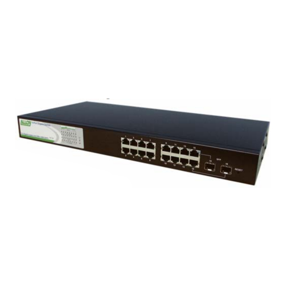
GSS-16T2SFP Switch 1.4.1. User Interfaces on the Front Panel (Button, LEDs and Plugs) There are 16x (GSS-16T2SFP model) or 24x (GSS-24T2SFPV2 model) copper RJ-45 Gigabit Ethernet ports and 2x SFP fibre ports for optional mini-GBIC modules (both models) on the front panel of the switch. The LED display area, located on the left side of the panel, contains a Power LED (which indicates the power status of the switch) and 16/24 LEDs that indicate the status of each of the RJ-45 ports on the switch. -
Page 12: User Interfaces On The Rear Panel
Amber when 100Mbps speed is active 10/100/1000Mbps Amber Off when 10Mbps speed is active LEDS for: SFP Gigabit Fibre Ports 15 & 16 (GSS-16T2SFP)* or SFP Gigabit Fibre Ports 23 & 24 (GSS-24TSFP)* On when connection with the remote device is good SFP(LINK/ACT) -
Page 13: Overview Of The Optional Sfp Modules
1.5. Overview of the Optional SFP Modules With the GSS-16T2SFP switch, the SFP ports are paired with RJ-45 copper ports 15 and 16. In the case of the GSS-24T2SFPV2, the SFP ports are paired with RJ-45 copper ports 23 and 24. Only one of any given paired port can be used. In this manner, these paired ports can be seen as ‘Dual Media’... -
Page 14: Installation
2. Installation 2.1. Starting the 16/24 Port Gigabit Web Managed Switches This section provides a quick start guide for: • Hardware and Cable Installation • Management Station Installation • Software booting and configuration 2.1.1. Hardware and Cable Installation Please Note: ⇒... - Page 15 2. Repeat the above steps, as needed, for each RJ-45 port to be connected. • Power On Please Note: ⇒ Alloy 16/24 Port Gigabit Switches use a 100-240 VAC, 50-60 Hz power supply. The power supply will automatically convert your local AC power source to DC power for use by the switch.
-
Page 16: Cabling Requirements
These are SX, LX, LHX, ZX and EZX. The majority of mini-GBIC modules available use a LC type connector. The connector types used currently on Alloy mini-GBIC modules are LC and WDM SC, for the following module types: •... - Page 17 Please Note: ⇒ Further in formation can be found in section 1.5 on page 7 ⇒ All figures denoting the range a given cable type can achieve must be treated as maximum values. A number of variables can limit the actual range that can be achieved –...
-
Page 18: Operation Of Web-Based Management
3. Operation of Web-based Management This chapter instructs you how to configure and manage Alloy 16/24 Port Gigabit Web Managed Switches through the web user interface. The default values of the GSS-16T2SFP and GSS-24T2SFPV2 Gigabit Web Managed Switches are as follows: IP Address 192.168.1.1... -
Page 19: Web Management Home Page Overview
3.1. Web Management Home Page Overview After you have successfully logged into the management interface screen, the system status information is displayed as in Fig. 3.2. This page informs you about the basic information of the system, including “Switch Status”, “TP Port Status”, “Fibre Port Status”, “Aggregation”, “VLAN”, “Mirror”, “Trap Event”, and “Maximum Packet Length”. -
Page 20: System" - The System Configuration Submenu
The functions of each group are described in the corresponded sections through the remainder of this manual. The organization of the submenus shown in diagrammatical format is shown in Fig. 3.3 Main Menu Configuration Monitoring Fig. 3.3 Maintenance 3.2. “System” – The System Configuration Submenu 11 functions are included in the System Configuration group. -
Page 21: System Configuration
3.2.1. System Configuration System configuration is one of the most important options in the management of the switch. Without proper configuration, the switch cannot be accessed or managed. The switch supports manual IP address settings. When the IP address is changed you must reboot the switch to have the settings take effect. - Page 22 * Used to set a logical name for the switch. Up to 16 alphanumeric characters and nulls are allowed in this parameter. Click the <apply> button to update the field. The default value is: GSS-16T2SFP Password (RW): * Used to set a password to access the switch’s management interface.
-
Page 23: Port Configuration Submenu
3.2.2. Port Configuration Submenu Fig. 3.6 • Function Name: Port Configuration • Function Port Configuration allows the various port settings to be changed • Description: • Parameter Mode: Description: * Used to set the speed and duplex parameters of a port. * If the media is 1Gbps fibre, then there are three modes to choose from: ‘Auto Speed’, ‘1000 Full’... -
Page 24: Vlan Mode Configuration
3.2.3. VLAN Mode Configuration Fig. 3.7 The switch supports Port-based VLAN and Tag-based VLAN (802.1q) 16 active VLANs are supported, with VLAN ID’s from 1-4094. VLAN configuration is used to partition your LAN into small broadcast domains (groups). Properly configuring VLANS can improve your network security and increase network performance by limiting broadcast propagation. - Page 25 specific policies on accepting or denying non- tagged packets. Each tag-based VLAN that is configured must be assigned a VLAN name and a VLAN ID. Valid VLAN ID’s are from 1 to 4094. Administrators can create a total of up to 16 Tag VLAN groups.
-
Page 26: Vlan Group Configuration
3.2.4. VLAN Group Configuration Fig. 3.8 • Function Name: Tag-based VLAN Group Configuration • Function In port-based VLAN mode, this will display the “ID - Description” Description: - and members of existing port-based VLAN groups. If in tag-based VLAN mode, this will display the “ID - Description – VID” and Members of the existing tag-based VLAN group. - Page 27 Fig. 3.9 Delete Group: * Select the check box ( beside the ID, to delete a group. Then press the <Delete Group> button to delete the group. Fig. 3.10...
-
Page 28: Pvid Configuration
3.2.5. PVID Configuration Fig. 3.11 • Function Name: PVID Configuration • Function From within this menu users can assign a VID number for Description: each port. The range of VID numbers is from 1 to 4094. You can also choose ingress filtering rules to each port. There are two ingress filtering rules which can be applied to the switch. - Page 29 Rule 2: * Drop untagged frame. You can configure a given port to accept all frames (Tagged and Untagged) or just receive tagged only frames. If the former is the case, then packets either tagged or untagged will be processed. If the later is the case, only packets carrying a VLAN tag will be processed, all other packets will be discarded.
-
Page 30: Aggregation Configuration
3.2.6. Aggregation Configuration Aggregation (Port Trunking) Configuration is used to configure Link Aggregation. You can bundle more than one port with the same speed and duplex settings to form a single logical port. The logical port aggregates the bandwidth of the individual member ports. This allows you to create a higher speed uplink or backbone connection via bandwidth aggregation. -
Page 31: Mirror Configuration
3.2.7 Mirror Configuration Fig. 3.13 • Function Name: Mirror Setting • Function Mirror Configuration used monitor traffic Description: the network. For example, assume that Port A is a ‘sniffer’ port Port B is the Source Port; configuring a mirror setting allows the traffic passed by Port B to be copied to Port A for monitoring purposes •... - Page 32 Fig. 3.14 The QoS function as VLAN Tag Priority mode, and then choose Default Class as High, the priority of the packets with no tags will be considered as High priority precedence. The initial value of the Default Class is 'High'. Fig.
- Page 33 Within the Layer 3 network framework is a TOS field for IP Description: headers. Alloy 16/24 Port Gigabit Switches can prioritise packet forwarding based on this TOS header. TOS Headers include 3 bits for 8 levels of TOS. Once again these 8 levels can be mapped to ‘High’...
- Page 34 (Mode Selection Screen) • Function In Layer 4 QoS Configuration you can prioritise packets Description: based on the application type that they contain; for example, to down prioritise web browsing, e-mail and FTP. Fig. 3.17 • Advanced/: Toggle the <Simple> / <Advanced> button to switch between Simple Mode configuration modes and to display details on the TCP/UDP ports configured (See Fig 3.18).
- Page 35 Fig. 3.18 • Advanced: The Advanced Configuration Mode interface box allows you Mode to further customise the initial simple configuration defaults with your own TCP/UDP port definitions, or to create your own definition list from scratch. (Refer to Fig 3.18) •...
- Page 36 (0-63) Description: Traffic Classifications based on a 6-bit field in the DSCP header of IP packets. The GSS-16T2SFP switch allows mapping of these 64 classifications to High or Low priority queues • Parameter IP Differentiated Services (DiffServe) Configuration: Description:...
-
Page 37: Bandwidth Management
3.2.9. Bandwidth Management • Function Name: Bandwidth Management Configuration • Function The Bandwidth Management function is used to set Ingress Description: and Egress bandwidth limits for each port Fig. 3.20 • Parameter Port Number: Description: * Select the port to which you want to add a Rate Control Policy. -
Page 38: Trap Event Configuration
3.2.10. Trap Event Configuration • Function Name: Trap Event Configuration • Function The Trap Event Configuration interface screen enables Alloy Description: 16/24 Port Gigabit Switches to send out trap information when pre- defined events occur on the network. The switch offers 7 different trap events and 2 configurable destination Trap Hosts. -
Page 39: Maximum Packet Length
3.2.11. Maximum Packet Length • Function Name: Maximum Packet Length • Function The switch is capable of dealing with 9k Jumbo Frames. Description: Jumbo frames are effective in point to point environments for large payload data transfers. They maximise the data-to- header payload ratio, so that more data is sent with less header information (note that both transmitting and receiving nodes need to support Jumbo Frames) -
Page 40: Monitoring
.3. Monitoring There are two functi ons contained in the monitoring section of the management. Monitoring Statistics Overview Detailed Statistics .3.1. Statistics Overview The Statistics Overview func tion collects summary information from port-based traffic counters. The type of data that can be collected includes information about Frames, Bytes, and Errors. -
Page 41: Detailed Statistics
* Total re ceived bytes Rx Frames: * The num ber of packets received Tx Errors: * The nu mber of bad packets transmitted Rx Errors: * The num ber of bad packets received Fig. 3.23a .3.2. Detailed Statistics • Function Name: Detailed Statistics •... - Page 42 • Parameter Received (Rx) Packets: Description: * The number of the packets received RX Octets: * Total received data in bytes Rx High Priority Packets: * Number of Rx packets classified as high priority Rx Low Priority Packets: * Number of Rx packets classified as low priority Rx Broadcast: * Number of broadcast packets received Rx Multicast:...
- Page 43 Rx 65-127 Bytes: * Number of 65 to 127-byte frames (includes non valid packets) received Rx 128-255 Bytes: * Number of 128 to 255-byte frames (includes non valid packets) received Rx 256-511 Bytes: * Number of 256 to 511-byte frames (includes non valid packets) received Rx 512-1023 Bytes: * Number of 512 to 1023-byte frames (includes non valid packets)
- Page 44 Tx 512-1023 Bytes: * Number of 512 to 1023-byte frames (includes non valid packets) transmitted Tx 1024-Bytes: * Number of 1024-maximum length byte frames (includes non valid packets) transmitted Rx CRC/Alignment: * Number of alignment errors/CRC error packets received Rx Undersize: * Number of short frames (64 Bytes or under) with valid CRC Rx Oversize: * Number of long frames (according to maximum length register)
-
Page 45: Maintenance
3.4. Maintenance There are four functions contained in the maintenance section. Maintenance Status Warm Restart Factory Default Logout 3.4.1. Status 8 sections are reported on in the switch status screen. These comprise: Switch status, TP Port Status, Fibre Port Status, Aggregation, VLAN, Mirror, Trap Event and Maximum Packet Length Status Switch Status... - Page 46 MAC Address: * Displays the Ethernet MAC address of the switch System Name: * Displays the Alloy part number for the model of the switch (i.e. GSS-16T2SFP for a 16 port Gigabit switch and GSS-24T2SFPV2 for a 24 port Gigabit switch)
-
Page 47: Utp And Fibre Ports Status
3.4.1.2. UTP & Fibre Port Status • Function Name: TP/Fibre Port Status • Function Displays a summary of the port status for both TP and Fibre Description: ports Fig. 3.26 • Parameter Port: Description: * Ports 1 to 16. Both ports 15 and 16 are optional SFP modules Link Status: * Displays the status of the link for the port: Options are: o <10FULL>:... -
Page 48: Aggregation
Two options are available to choose from: <Enable> and <Disable>. The default mode is <Enabled>. There are two types of Flow Control supported by Ethernet (Both supported by Alloy Gigabit Switches): o Pause flow control: As stipulated by IEEE standard 802.3x, for full-... -
Page 49: Vlan
3.4.1.4. VLAN • Function Name: VLAN Status • Function Display which VLAN mode the switch is operating with, and Description: details of VLAN group settings. • Parameter VLAN Mode: Description: * Displays the 3 supported VLAN modes, with status displayed for each mode. -
Page 50: Mirror
3.4.1.5. Mirror • Function Name: Mirror Status • Function Mirror Status displays the current mirror configuration Description: Fig. 3.31 • Parameter Sniffer Mode: Description: * Displays the mirror status. The default is “disabled” Sniffer Port: * Displays the number of the port that is receiving the monitored data Source Port: * Displays the number of the port that is being... - Page 51 • Parameter Trap IP (1 and 2): Description: * The IP address of 1 or 2 two P.C.’s which can access trap event data and receive trap event warnings can be entered here. Current IP addresses are displayed as status information Boot: * Two parameters are available for Boot Traps.
-
Page 52: Maximum Packet Length
Fig. 3.33 3.4.2. Warm Restart The management interface for Alloy 16/24 Port Gigabit Switches offers a Warm Restart option. This simply reboots the switch with the current switch settings intact. (Optionally you could also press the RESET button on the front panel to reset the switch). -
Page 53: Restore Default Configuration
3.4.3. Restore Default Configuration • Function Name: Restore Default Configuration • Function The Factory Default function will reset the current configuration Description: settings of the switch, and replace them with the original Factory Default settings. Fig. 3.35... -
Page 54: Logout
3.4.4. Logout Alloy 16/24 Gigabit Switches supports a web management auto-logout (see section 3.2.1) from the web interface, but there is also a manual logout function. If you need to release control of the web management so that another user can access it immediately, then you can manually perform a Logout with this function. -
Page 55: Maintenance And Basic Troubleshooting
The following items should be kept in mind: Fans: Alloy 16/24 Port Gigabit Switches use a fan to ensure good levels of airflow in the switch case. The fan does not need maintenance. As the only moving part in the switch, this is the only possible source of mechanical noise inside the switch. -
Page 56: Basic Troubleshooting
Switch, Hub etc) is an older legacy device, it may not support Nway auto-negotiation, as in the case of modern switches. In such cases, it is possible that your Alloy 16/24 Gigabit switch has not been able to synch speed and/or duplex characteristics correctly with the legacy device. - Page 57 ⇒ Problems of this type can have many causes. However, if the LED indicators on your Alloy 16/24 Gigabit switch show such problems, check that network cards used in your system are functioning correctly. Faulty Network Adapters can propagate high...
-
Page 58: Appendix A Technical Specifications
• 2 Gigabit Copper/SFP paired ports for support of Fibre or Copper Mini-GBIC media. SFP ports are paired with TP ports 15 and 16 (GSS-16T2SFP) and ports 23 and 24 (GSS- 24T2SFPV2). Only one of the two paired ports can be used at any one time •... - Page 59 1000 FDX SFP 23, 24 (GSS-16T2SFP) Notes: 1: Ports 15 & 16 (GSS-16T2SFP) and 23 & 24 (GSS-16T2SFP) are paired copper TP RJ-45/SFP fibre module slot dual media ports. Only one port from each pair can be used at any given point. The paired ports have...
- Page 60 Maximum Cable Length: Cat. 5 UTP cable or higher, max. range to 100m Up to 220/275/500/550 metres, 1000Base-SX Depending on Multimode Fibre type and quality Singlemode Fibre, various distances 1000Base-LX 10/30/50Km etc… 1000Base-LX WDM Singlemode Single Fibre, up to 20Km Diagnostic LED: System LED : Power...
Need help?
Do you have a question about the GSS-16T2SFP and is the answer not in the manual?
Questions and answers