Table of Contents
Advertisement
Quick Links
User Manual
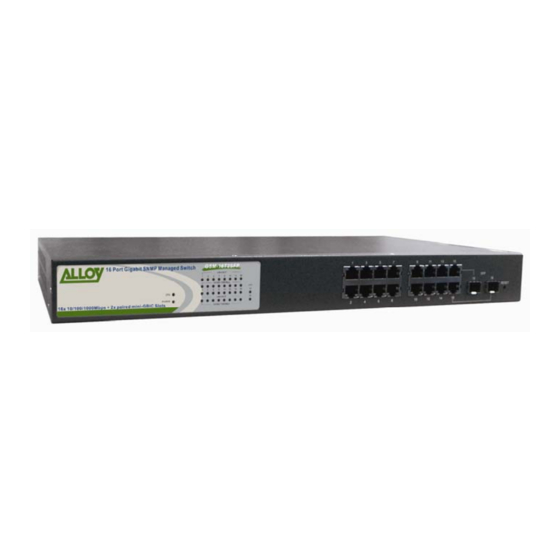
16 Port Gigabit SNMP Managed Switch
16x 10/100/1000Mbps ports + 2 paired SFP Ports
24 Port Gigabit SNMP Managed Switch
24x 10/100/1000Mbps ports + 2 paired SFP Ports
24 Port Gigabit SNMP Managed Switch
8x 10/100/1000Mbps ports + 16 SFP Ports
GSM-16T2SFP
GSM-24T2SFP
GSM-8T16SFP
Version: 1.01
March 1, 2006
Advertisement
Table of Contents

Related Manuals for Alloy GSM-16T2SFP


Summary of Contents for Alloy GSM-16T2SFP
-
Page 1: User Manual
User Manual GSM-16T2SFP 16 Port Gigabit SNMP Managed Switch 16x 10/100/1000Mbps ports + 2 paired SFP Ports GSM-24T2SFP 24 Port Gigabit SNMP Managed Switch 24x 10/100/1000Mbps ports + 2 paired SFP Ports GSM-8T16SFP 24 Port Gigabit SNMP Managed Switch 8x 10/100/1000Mbps ports + 16 SFP Ports Version: 1.01... -
Page 2: Table Of Contents
3-11-2. MAC Table Maintenance...70 3-11-3. Static Forward ...71 3-11-4. Static Filter ...72 3-11-5. MAC Alias ...73 3-12. GVRP ...74 3-12-1. GVRP Configuration ...74 3-12-2. GVRP Counter...76 Alloy Computer Products Pty Ltd Copyright ©2006 GSM Series User Manual ONTENTS ...1 ...2 ANAGED WITCHES ...5... - Page 3 ... 114 ANAGEMENT 4-1-1. Login ... 114 4-2. C CLI ... 115 OMMANDS OF THE 4-2-1. Global Commands of the CLI ... 117 4-2-2. Local Commands of CLI ...123 Alloy Computer Products Pty Ltd Copyright ©2006 GSM Series User Manual...
-
Page 4: Caution
Touch the metal chassis of your computer to ground the static electrical charge before you handle the switch. • Pick up the switch by holding it on the left and right edges only. Electronic Emission Notices Federal Communications Commission (FCC) Statement... -
Page 5: About This User Manual
For the purposes of this User Manual the illustrations included are of the GSM-16T2SFP model. If the model you have purchased is the GSM-24T2SFP or GSM-8T16SFP, please bear in mind that your switch has 24x 10/100/1000Mbps ports or 8x 10/100/1000Mbps ports and 16x Mini- GBIC ports. -
Page 6: Overview Of Gsm Series Snmp Managed Switches
Intelligent Network features, offer a complete management solution that can enable you to scale your network from a single departmental switch right up to any Enterprise environment. STP and RSTP offer network redundancy features, IGMP snooping offers support for Streaming Video and Multicasting images, Tagged VLAN offers logical security and management of nodes within defined groups. -
Page 7: Checklist
Port Trunking: Allows two or more links to be aggregated together to form a Link Aggregation Group (LAG). Up to 12 Gigabit ports can be set up per trunk, and a switch can support up to 8 trunking groups. Port trunks are useful for switch-to-switch cascading, providing very high full-duplex connection speeds. -
Page 8: Features
1.3. Features Alloy GSM Series Switches provide a comprehensive range of features: • Hardware • 14 10/100/1000Mbps Auto-negotiation Gigabit Ethernet Ports (GSM-16T2SFP) • 22 10/100/1000Mbps Auto-negotiation Gigabit Ethernet Ports (GSM-24T2SFP) • 8 10/100/1000Mbps Auto-negotiation Gigabit Ethernet Ports (GSM-8T16SFP) • 2 Paired 10/100/1000Mbps or 1000Mbps SFP Mini-GBIC Ports (GSM-16T2SFP &... -
Page 9: Overview Of Gsm Series Switches
• TFTP for firmware upgrade, system log upload and config file import/export 1.4. Overview of GSM Series Switches Fig. 1-1: Front View of the GSM-16T2SFP Switch Fig. 1-2: Front View of the GSM-24T2SFP Switch Fig. 1-3: Front View of the GSM-8T16SFP Switch Alloy Computer Products Pty Ltd Copyright ©2006... -
Page 10: User Interfaces On The Front Panel (Button, Led's And Plugs)
There are 16x (GSM-16T2SFP), 24x (GSM-24T2SFP) or 8x (GSM-8T16SFP) copper RJ-45 Gigabit Ethernet ports and 2x SFP fibre ports (GSM-16T2SFP & GSM-24T2SFP) or 16x SFP fibre ports (GSM-8T16SFP) for optional mini-GBIC modules on the front panel of the switch. The... -
Page 11: User Interfaces On The Rear Panel
1.5. Overview of the Optional SFP Modules With the GSM-16T2SFP switch, the SFP ports are paired with RJ-45 copper ports 15 and 16. In the case of the GSM-24T2SFP, the SFP ports are paired with RJ-45 copper ports 23 and 24. - Page 12 The two units must be used in a paired manner, one at either end of the link. Mini-GBIC modules that are designed to the relevant standards should be compatible with any make of switch with SFP ports. If you have concerns regarding compatibility, please contact the supplier of your mini-GBIC product.
-
Page 13: Starting The Gsm Series Snmp Managed Switches
Please Note: ⇒ Wear a grounding strap to avoid damaging the switch with an electrostatic discharge ⇒ Be sure that the power switch is in the ‘OFF’ position before you insert the power cord Installing Optional SFP Mini-GBIC Modules •... - Page 14 ⇒ The minimum grade of cable for use with the switch is Cat. 5 grade UTP or STP. Higher grades of UTP/STP cable may also be used to connect to the copper RJ-45 ports.
-
Page 15: Cabling Requirements
Single-mode transceiver 1310nm 10Km, 40Km LX/LHX/XD/ZX Single-mode transceiver 1550nm 40Km, 70Km, 100Km Single-mode 1000Base-LX *20Km Single Fibre (WDM SC) Single-mode *20Km Alloy Computer Products Pty Ltd Copyright ©2006 GSM Series User Manual Multimode 50/125μm Modal Range Bandwidth 220m 400MHz-Km 275m 500MHz-Km Single-mode Fibre 9/125μm... -
Page 16: Management Options Available With The Gsm Series Switches
Username: admin Password: admin The RS-232 console port on the switch is mainly used for the initial setup of the switch including setting the IP Address, Subnet Mask and Gateway. It is recommended that all other management duties that need to be performed should be done via the Web Management or CLI. - Page 17 To set or change the default IP address of the switch via the console port, please follow the steps below: 1. Log into the switch via hyper terminal using the above settings. 2. Type IP and press Enter to enter the IP configuration mode.
-
Page 18: Configuring The Gsm Series Switches Through The Ethernet Port
Network Management Software that is being used. Note: MIB files can be located for each switch on the CD-ROM, which can then be used with your Network Management Software. - Page 19 If using the CLI open a command prompt and create a telnet session to the default IP Address of the switch. You will now be prompted to log into the switch, the default username and password is shown below: Username: admin Password: admin Fig.
- Page 20 Username: admin Password: admin Once you have entered the IP address of the GSM Series switch into a web browser you will be prompted with a login screen where you will need to enter a valid username and password to gain access to the switch.
-
Page 21: Web Management Home Overview
GSM Series User Manual 3-1. Web Management Home Overview Once you have entered a valid username and password and logged into the switch the System Information page will be displayed, this is the default page, it will be displayed every time that you log into the switch. - Page 22 At the top of the page, there is a picture of the front panel of the switch. The picture displays the port status of each of the ports on the switch. If the port is green this tells us that the port has an active connection, if the port is grey then no link is present.
-
Page 23: System Information
Device Name: Specify a descriptive device name for the switch. Location name can be up to 36 Alphanumeric Characters long. Click the <apply> button to update. (Read/Write) Alloy Computer Products Pty Ltd Copyright ©2006 GSM Series User Manual Fig. 3-5... - Page 24 The time accumulated since last power up. Format is Day, Hour, Minute, Second. (Read Only) Current Time: Shows the system time of the switch. Format is Day of week, Month, Day, Hours, Minutes, Seconds, Year. Eg Mon Jan 16 3:46:49 2006 (Read Only) BIOS Version: The version of the BIOS in the switch.
-
Page 25: Ip Configuration
3-1-2. IP Configuration The IP configuration is used to set the IP settings in the switch. The GSM Series switches support either a static IP address allocated to them via the system administrator or can be assigned an IP address dynamically from a DHCP server on your network. The IP address is used to gain access to the management functionality of the switch. - Page 26 If DHCP has been enabled the switch will receive a DNS IP Address dynamically from the DHCP Server. If you are not using DHCP you will need to set a DNS address in the switch. A DNS Server address should be given to you from your ISP.
-
Page 27: Time Configuration
3-1-3. Time Configuration The GSM Series switches provide two methods to keep the switch’s time settings correct, they are via manual input and via a Time Server on the internet. If you are manually entering your time settings enter the “Year”, “Month”, “Day, “Hour”, “Minute” and “Seconds” into the space provided. - Page 28 The Time Zone is an offset time of the GMT. The switch supports a configurable time zone from -12 to +13 hours in increments of 1 hour.
-
Page 29: Account Configuration
GSM Series switches allow the administrator to create up to 5 guest accounts, accounts can only be created by the administrator. When a Guest user logs into the switch they will not be able to modify any parameters, they just have read only rights to the switch. A Guest user can log into the switch and change there own password, but will not be able to modify any other accounts. - Page 30 Please enter a username for the administrator or guest account, a maximum of 15 alphanumeric characters only. Password: Please enter a password for the administrator or guest account, a maximum of 15 alphanumeric characters only. Confirm Password: Please confirm the password. Alloy Computer Products Pty Ltd Copyright ©2006 GSM Series User Manual...
-
Page 31: Management Security Configuration
Rules can also be created to allow access to management from certain switch ports only. Eg only port 5 has access to the switch’s management. Rules can then be broken down even further to allow particular management access to these VLAN groups, IP Ranges or Ports. - Page 32 Incoming Port: If you want to lock the management interface access down to certain ports on your switch please select the Custom radio button and tick the required ports which will allow/deny access to the management. Otherwise select the Any radio button.
-
Page 33: Virtual Stack Configuration
Administrators will only need to know the IP address of the master switch to gain access to all GSM Series switches on the network. An additional table will appear above the web management screen showing all switches that belong to the virtual stacking group. -
Page 34: Port Configuration
Additional Information is also available for ports 15 and 16 (GSM- 16T2SFP) or 23 and 24 (GSM-24T2SFP) or 9 to 24 (GSM-8T16SFP) when running SFP modules. Fig. 3-12 Alloy Computer Products Pty Ltd Copyright ©2006... - Page 35 Parameter Description: Port No: Displays every port on the switch. If the port is paired with another port you will see that port 15 and port 15b will be displayed. This applies for the GSM- 16T2SFP and GSM-24T2SFP where they have 2 copper ports that are paired with 2 SFP Fibre ports.
- Page 36 1310nm, 1550nm and so on. Baud Rate: Displays the maximum speed the SFP module supports. Vendor OUI: Displays the manufacturers OUI code which is assigned by the IEEE. Alloy Computer Products Pty Ltd Copyright ©2006 GSM Series User Manual Fig. 3-13...
- Page 37 Mon1(Bias) mA: Shows the Bias current of the SFP module. Mon2(TX PWR): Shows the transmit power of the SFP Module. Mon3(RX PWR): Shows the receive power of the SFP Module. Alloy Computer Products Pty Ltd Copyright ©2006 GSM Series User Manual...
-
Page 38: Port Configuration
Parameter Description: Port No: Displays every port on the switch, if the port is paired with another port you will see that port 15 and port 15b will be displayed. This applies for the GSM- 16T2SFP and GSM-24T2SFP where they have 2 copper ports that are paired with 2 SFP Fibre ports. - Page 39 Shows the port’s flow control status. The GSM Series switches support both Backpressure flow control for Half Duplex and Pause flow control for Full Duplex. Select Enable to enable flow control and Disable to disable flow control. Default: Enabled Alloy Computer Products Pty Ltd Copyright ©2006...
-
Page 40: Simple Counter
Fig. 3-15 shows you a screen shot of the simple counter screen. As you can see from the image all ports on the switch are displayed at one time. If the amount of data being displayed on the screen is more that 12 digits long, the counter will be reset back to zero and continue on. - Page 41 Displays the total amount of bad packets received. Refresh Interval: The user can define the amount of time the switch will take to update the ports statistics. This is measured in seconds and ranges from 3 – 10. Default: 3 seconds.
-
Page 42: Detail Counter
RX High Priority Packets: Displays the total number of received packets classified as High Priority. RX Low Priority Packets: Displays the total number of received packets classified as Low Priority. Alloy Computer Products Pty Ltd Copyright ©2006 GSM Series User Manual Fig. 3-16... - Page 43 TX 65 ~ 127 Bytes: Displays the total number of 65 ~ 127 byte frames transmitted. TX 128 ~ 255 Bytes: Displays the total number of 128 ~ 255 byte frames transmitted. Alloy Computer Products Pty Ltd Copyright ©2006 GSM Series User Manual...
- Page 44 Used to select what ports statistics are being displayed. Refresh Interval: The user can define the amount of time the switch will take to update the ports statistics this is measured in seconds and ranges from 3 – 10. Default: 3 seconds.
-
Page 45: Mirror
Here you can select which port is going to be used as the monitoring port. You can select any port on the switch in the case of the GSM-16T2SFP, ports 1 -16 can be selected and 1 – 24 for the GSM-24T2SFP and GSM-8T16SFP. -
Page 46: Bandwidth
Flow Control is enabled. The Ingress Rate Limiting will limit all data including unicast, broadcast and multicast traffic. Valid range is 0 ~ 1000. Default State: Disable Alloy Computer Products Pty Ltd Copyright ©2006 GSM Series User Manual Fig. 3-18... - Page 47 Traffic may be lost if the egress buffers are full. The Egress Rate Limiting will limit all data including unicast, broadcast and multicast traffic. Valid range is 0 ~ 1000. Default State: Disable Alloy Computer Products Pty Ltd Copyright ©2006 GSM Series User Manual...
-
Page 48: Qos (Quality Of Service)
The GSM Series switches allow the administrator to configure High and Low priority levels to individual ports on the switch. For instance if port 1 is set to High priority and port 2 is set to Low priority and both ports are transmitting data at 1G to port 5, packets transmitted from port 2 will be dropped if there is congestion in the switch. - Page 49 8 types of traffic classifications, including 000, 001, 010, 011, 100, 101, 110 and 111. Class: You can now assign a High or Low priority level to each of the 8 traffic classes. Alloy Computer Products Pty Ltd Copyright ©2006 GSM Series User Manual Fig. 3-20...
- Page 50 1 with a TOS field of 000 and packets to port 2 with a TOS field of 001 at 1Gb to port 3 of the switch and the switch becomes congested packets from port 2 may be partially dropped due to the lower priority levels.
- Page 51 The GSM Series switches allow the administrator to configure QoS rules based on Layer 4 networking protocols such as HTTP, FTP etc. The switch provides built in rules to down prioritise, or prioritise different types of services. If the built in rules do not suit your particular application, custom services can also be created based on a particular TCP/UDP port number.
- Page 52 Prioritise IP Telephony (VoIP): 1718, 1719, 1720 Prioritise iSCSI: 3225, 3260, 3420 Prioritise web browsing, email, FTP and news: 80, 280, 443, 25, 110, 20, 21, 69, 119, 2009 Alloy Computer Products Pty Ltd Copyright ©2006 GSM Series User Manual...
- Page 53 Prioritise Streaming Audio/Video: 2979, 1755, 7070, 7071, 554, 8000 Prioritise Databases (Oracle, IBM DB2, SQL, Microsoft): 66, 1571, 1575, 523, 118, 156, 3306, 1232, 1433, 1434 Fig. 3-22 Advanced Mode Fig. 3-23 Simple Mode Alloy Computer Products Pty Ltd Copyright ©2006 GSM Series User Manual...
- Page 54 Displays the 64 traffic classes in which a priority level can be assigned. Class: Set a High or Low priority level to any of the 64 different traffic classes. Alloy Computer Products Pty Ltd Copyright ©2006 GSM Series User Manual Fig. 3-24...
-
Page 55: Snmp Configuration
SNMP managers and agents and traverses the Object Identity (OID) of the Management Information Base (MIB), described in the form of SMI syntax. The SNMP agent is running on the switch to respond to requests issued by an SNMP manager. - Page 56 IP address; which are user-definable. To configure a Trap host you will need a network management System to receive the Trap messages from the switch. Six Trap hosts can be configured to allow the trap messages to be received by multiple recipients.
-
Page 57: Igmp Snooping
The GSM Series switches support all functions of IGMP Snooping including query, report and leave. IGMP Snooping is used by the switch to learn who belongs to a multicast group and also update the multicast table within the switch with new multicast members. Once the switch has learned who belongs to the multicast group all packets forwarded to a multicast address will be forwarded to all members belonging to the multicast group. - Page 58 To disable IGMP select the disable radio button and click Apply. Active: When using Active mode the switch will periodically issue the membership query message to all hosts attached to the switch and update the multicast table respectively. By using Active mode you will reduce multicast traffic on your network.
-
Page 59: Allowed Group
Edit button. If you wish to delete an existing rule highlight the required rule and click the Delete button. Alloy Computer Products Pty Ltd Copyright ©2006 GSM Series User Manual Fig. 3-27... -
Page 60: Max. Packet Length
The port number in which you wish to apply a smaller or larger packet size. Max. Frame Size: Used to set the maximum length of the packet that each port of the switch can accept. There are three sizes that can be selected 1518, 1532 and 9216. -
Page 61: Dhcp Boot
DHCP. The switch supports a random delay time for DHCP and boot delay for each device. This suppresses the broadcast storm while all devices on the network are booting at the same time. -
Page 62: Vlan (Virtual Local Area Network)
VLAN group in which it belongs. A typical example of where a VLAN could be used is in a school environment where the teacher and student networks must be kept separate. The switch supports up to 256 active VLAN entries and a VLAN ID ranging from 1 – 4096. - Page 63 Metro Mode: Metro mode is a quick and easy configuration of port-based VLAN’s. Metro mode quickly separates the switch into 14 or 15 (GSM-16T2SFP) 23 or 24 (GSM- 24T2SFP, GSM-8T16SFP) port-based VLAN groups. All ports on the switch are configured into separate VLAN groups and can not communicate with each other.
- Page 64 (depending on model) port-based VLAN groups containing two member ports in each group. 15 & 16 (GSM-16T2SFP) 23 & 24 (GSM-24T2SFP, GSM-8T16SFP): Each port of the switch can no longer communicate with each other, they can only communicate with the uplink ports chosen therefore creating 14 or 22 (depending on model) port-based VLAN groups containing three member ports in each group.
-
Page 65: Tag-Based Group
VID is the VLAN Identifier. Each tag-based VLAN group must have a unique VID. SYM-VLAN: Used to add additional security to the switch. If the SYM-VLAN function of the group is enabled, all packets with this group VID will be dropped in case they are transmitted from the ports that do not belong to this group. - Page 66 VLAN group from the table. Edit: Highlight the VLAN group you wish to edit and click the Edit button to modify the selected VLAN group. Alloy Computer Products Pty Ltd Copyright ©2006 GSM Series User Manual Fig. 3-33 Fig. 3-34...
-
Page 67: Port-Based Group
Port-based Group Configuration Function description: Shows information of the existing port-based VLAN groups, the administrator can also Add, Delete and Edit VLAN’s using the function buttons provided. Alloy Computer Products Pty Ltd Copyright ©2006 GSM Series User Manual Fig. 3-35 Fig. 3-36... - Page 68 Click the Apply button for the settings to take effect. Delete: Highlight the VLAN group you wish to delete and click the Delete button to remove the VLAN group from the table. Alloy Computer Products Pty Ltd Copyright ©2006 GSM Series User Manual Fig. 3-37...
- Page 69 Edit: Highlight the VLAN group you wish to edit and click the Edit button to modify the selected VLAN group. Alloy Computer Products Pty Ltd Copyright ©2006 GSM Series User Manual Fig. 3-38 Fig. 3-39...
-
Page 70: Tag Rule
Tag Rule Function description: The administrator can apply a VID to each port of the switch; the valid range of the VID is from 1 to 4094. Ingress filtering rules can also be applied to each port, there are two rules that can be applied Rule 1 “Forward only packets with VID matching this ports... - Page 71 VID matches the VID configured in the Untag VID section. Untag VID: Valid range is 0 – 4094. This will only work if the Role is set to Hybrid. Alloy Computer Products Pty Ltd Copyright ©2006 GSM Series User Manual Fig. 3-41...
-
Page 72: Mac Table
The MAC Table configuration can be used by the administrator to statically add MAC entries to the switches MAC table, display MAC address information from connecting devices, allow you to flush the switches MAC table and also allow you to configure the MAC age out time of the switch. 3-11-1. MAC Table Information... - Page 73 MAC address connected to all ports of the switch. If you wish to search for a particular MAC address, enter the MAC address in the Search section and click Search.
-
Page 74: Mac Table Maintenance
After a MAC address has been learned by the switch the MAC address is stored in the MAC table of the switch. If the MAC address is no longer used the switch will drop the MAC address from the table after a certain period of time. This time can be defined by the administrator. -
Page 75: Static Forward
The Static Forward function is used to associate a MAC address to a particular port of the switch. When a MAC address is assigned to a specific port all of the switches traffic sent to that MAC address will be forwarded to this port. -
Page 76: Static Filter
Function description: The Static Filter function allows the administrator to block MAC addresses from being forwarded by the switch. If a MAC address belongs to the Static Filtering table the switch will discard all traffic from that MAC address. The administrator can easily add MAC addresses to the Static Filter table by entering the MAC Address, VID and Alias fields. -
Page 77: Mac Alias
Delete button. Parameters description: MAC: Enter the MAC address you wish to assign a user friendly name to. Alias: Enter a user friendly name for the MAC address. Alloy Computer Products Pty Ltd Copyright ©2006 GSM Series User Manual Fig. 3-46... -
Page 78: Gvrp
GARP application that provides the 802.1Q-compliant VLAN pruning and dynamic VLAN creation on 802.1Q trunk ports. With GVRP, the switch can exchange VLAN configuration information with other GVRP switches, prune unnecessary broadcast and unknown unicast traffic, and dynamically create and manage VLAN’s on switches connected through 802.1Q trunk ports. - Page 79 The switch participates normally in the GARP protocol exchanges. This is the default setting. Non-Participant: In this mode the switch does not send or reply to any GARP messages, it just listens to messages and reacts to any received GVRP BPDU. Default Registrar Mode: There are three types of administrative control values that can be set, they are normal registrar, fixed registrar and forbidden registrar.
-
Page 80: Gvrp Counter
Enabled: The switch will not create dynamic VLAN’s when this port receives GVRP BDU, except if it receives a dynamic VLAN message and the GVRP PDU is an existing static VLAN entry. 3-12-2. GVRP Counter Function name: GVRP Counter Function description: All GVRP counters are divided into Received and Transmitted sections to allow you to monitor all GVRP actions. - Page 81 Leave Empty Message Packets: The total number of GARP BPDU with Leave Empty Messages transmitted by the GARP application. Empty Message Packets: The total number of GARP BPDU with Empty Messages transmitted by the GARP application. Alloy Computer Products Pty Ltd Copyright ©2006...
-
Page 82: Gvrp Group Information
When you have created a GVRP group, you can use the Administrative control function to change the Applicant and Registrar modes of the GVRP group. Refresh: Click the refresh button to get current GVRP group status. Alloy Computer Products Pty Ltd Copyright ©2006 GSM Series User Manual Fig. 3-49... -
Page 83: Stp
The Spanning Tree Protocol (STP) is a standardised method (IEEE 802.1D) for avoiding loops in switched networks. When STP is enabled, the switch will ensure that only one path is active between any two nodes on the network at a time. The administrator can enable Spanning Tree Protocol via the switch’s web management and then set up other advanced items. - Page 84 Shows the accumulated time in units of seconds since the last STP Topology Change was made. When a Topology Change is initiated again, this counter will be reset to 0. Alloy Computer Products Pty Ltd Copyright ©2006 GSM Series User Manual...
-
Page 85: Stp Configuration
If you wish the GSM Series switch to be the root bridge you will need to ensure that other bridges on your network have a higher bridge priority than that of this switch. The valid value is 0 –... - Page 86 Max. Age: If the GSM Series switch is the root bridge, the whole network will apply this figure as their maximum age time. When a switch receives a BPDU message originating from the root bridge and if the message age exceeds the maximum age of the bridge, the bridge will treat the root bridge as malfunctioned and issue a Topology Change Notification (TCN) BPDU to all other bridges.
-
Page 87: Stp Port Configuration
Path Cost Status: Determines the shortest path to the root bridge, the smaller the path cost value the more possible the port will become the root port. Alloy Computer Products Pty Ltd Copyright ©2006 GSM Series User Manual Fig. 3-52... - Page 88 STP BPDU at the next transmission. The only benefit of this operation is to make the port quickly act as an RSTP port. Click the <M Check> button to send a RSTP BPDU from the port you specified. Alloy Computer Products Pty Ltd Copyright ©2006 GSM Series User Manual...
-
Page 89: Trunking Configuration
Aggregation can bundle more than one port with the same speed, full duplex and the same MAC address to be a single logical port, thus the logical port aggregates the bandwidth of these ports. This allows the switch to aggregate multiple ports together to form a high bandwidth backbone link. -
Page 90: Trunk Port Settings/Status
3-14-1. Trunk Port Settings/Status Function name: Port Settings/Status Function description: Port Settings/Status is used to configure the trunk properties of each port on the switch. Parameters description: Method: Determines the method the port will use to aggregate with other ports. - Page 91 Status: This field represents the status of a port belonging to a trunking group. Alloy Computer Products Pty Ltd Copyright ©2006 GSM Series User Manual...
-
Page 92: Aggregator View
Shows the method the port uses to aggregate with other ports. Member Ports: Shows all member ports of an aggregator. Ready Ports: Shows only the ready member ports within an aggregator. Alloy Computer Products Pty Ltd Copyright ©2006 GSM Series User Manual Fig. 3-54... -
Page 93: Lacp Detail
Shows the key value of the aggregator. The key value is determined by the LACP protocol entity and can’t be set through the management. Trunk Status: Shows the trunk status of a single port. Alloy Computer Products Pty Ltd Copyright ©2006 GSM Series User Manual Fig. 3-55... -
Page 94: Lacp System Priority
The LACP System Priority is used to set the priority of the LACP system ID. LACP will only aggregate ports whose partner ports belong to a single switch. Each system that has support for LACP will be assigned a globally unique System Identifier for this purpose. A system ID is a 64-bit field comprising of a 48-bit MAC address and a 16-bit priority value. -
Page 95: Configuration
A device that provides the authentication service, through EAP, to an authenticator by using authentication credentials supplied by the supplicant to determine if the supplicant is authorised to access the network resource. Alloy Computer Products Pty Ltd Copyright ©2006 GSM Series User Manual... - Page 96 Supplicant’s Authenticator’s System System Services Offered by Authenticator Supplicant (e.g Bridge Relay) Controlled port Alloy Computer Products Pty Ltd Copyright ©2006 GSM Series User Manual Authenticator Uncontrolled port Port Authorize MAC Enable Fig. 3-57 Authentication Server’s System...
- Page 97 B and C are on the internal network, D is the Authentication server running RADIUS, the switch at the central location acts as the Authenticator connecting to PC A and A is a PC outside the controlled port, running Supplicant PAE. In this case, PC A wants to access the services on device B and C, first, it must exchange the authentication message with the authenticator on the port it is connected via EAPOL packet.
-
Page 98: State
The secret key is used to authenticate the RADIUS server with the Authenticator. The secret key is an ASCII based string with a length of 1 – 31 characters, with no blank spaces allowed. Default: Radius Alloy Computer Products Pty Ltd Copyright ©2006 GSM Series User Manual Fig. 3-59... -
Page 99: Mode
There are two modes that can be selected, they are Disabled and Multihost mode. Disable: The selected port will not use 802.1x authentication. Multihost: Once the supplicant has been authenticated they can then access network resources through that port. Alloy Computer Products Pty Ltd Copyright ©2006 GSM Series User Manual Fig. 3-60... -
Page 100: Security
If the port has been authorised, authorised will be displayed in the ports status section, if the user has not been authorised, then unauthorised will be displayed. Alloy Computer Products Pty Ltd Copyright ©2006 GSM Series User Manual Fig. 3-61... -
Page 101: Parameter Setting
Default: Auto reAuthMAx (1-10): The number of authentication attempts that are permitted before the port becomes unauthorised. Default: 2 Alloy Computer Products Pty Ltd Copyright ©2006 GSM Series User Manual Fig. 3-62... - Page 102 Valid range: 1 – 65535. Default: 30 serverTimeout (1- 65535 sec.): A time out condition in the exchange between the authenticator and the authentication server. Valid range: 1 – 65535. Default: 30 Alloy Computer Products Pty Ltd Copyright ©2006 GSM Series User Manual...
-
Page 103: Alarm Configuration
The GSM Series switches support a number of trap messages that can be sent to an administrator if certain events occur on the switch. The switch offers 24 different trap events that can be sent to the administrator in 3 different ways; email, mobile phone SMS or trap. - Page 104 Tick the required trap method check box to enable a trap to be sent when a LACP Port has failed. GVRP Disabled: Tick the required trap method check box to enable a trap to be sent when GVRP has been disabled. Alloy Computer Products Pty Ltd Copyright ©2006 GSM Series User Manual...
- Page 105 Tick the required trap method check box to enable a trap to be sent when the dual media port has been swapped from fibre to copper or vice versa. Alloy Computer Products Pty Ltd Copyright ©2006 GSM Series User Manual...
-
Page 106: Email/Sms Configuration
Enter the email address(s) that will receive the trap messages. SMS Server: Enter the IP Address of the SMS server used to send SMS messages. Username: Enter the username required by the SMS server. Alloy Computer Products Pty Ltd Copyright ©2006 GSM Series User Manual Fig. 3-64... - Page 107 Password: Enter the password required by the SMS server. Email Address 1 – 6: Enter the mobile phone number(s) that will receive the trap messages. Alloy Computer Products Pty Ltd Copyright ©2006 GSM Series User Manual...
-
Page 108: Configuration
In this section the administrator can save the switch’s configuration, restore the switch to factory default and also save the current configuration as the startup configuration when the switch is re-booted. -
Page 109: Config File
Enter the file path of where you would like to import the configuration file from. Import Start: After configuring the import path click on the import start button to import the startup configuration file. Import User-Conf: Alloy Computer Products Pty Ltd Copyright ©2006 GSM Series User Manual Fig. 3-66... -
Page 110: Diagnostics
Self tests the UART in the switch. DRAM Test: Self test the DRAM used in the switch. Flash Test: Self test the Flash RAM used in the switch. Alloy Computer Products Pty Ltd Copyright ©2006 GSM Series User Manual Fig. 3-67... -
Page 111: Loopback Test
External loopback test. The internal loopback test is an internal test and no test signal is sent out of the switch. The external loopback test will send the test signal to its link partner to check if the port has got an active link. If there is no active link the external loopback test will fail. -
Page 112: Ping Test
3-18-3. Ping Test Function name: Ping Test Function description: The GSM Series switches support a ping test function to allow the switch to test communication between other IP based devices. Parameters description: IP Address: Enter an IP Address that you would like to test connectivity between. -
Page 113: Tftp Server
Function name: TFTP Server Function description: Used to set the IP address of the TFTP Server. Parameters description: Server: Enter the IP address of the TFTP Server. Alloy Computer Products Pty Ltd Copyright ©2006 GSM Series User Manual Fig. 3-70... -
Page 114: Log
Function description: The Trap Log Data displays all SNMP Private trap events, SNMP Public traps and all other user logs. The GSM Series switch support up to 120 log entries. Parameters description: Displays the order number of all entries in the log. -
Page 115: Firmware Upgrade
3-21. Firmware Upgrade The GSM Series switches allow the administrator to upgrade the firmware to improve the features and capabilities of the switch. The firmware is upgraded via a TFTP server using any Ethernet port on the switch. Function name:... -
Page 116: Reboot
3-22. Reboot The GSM Series of switches allow the Administrator to reboot the switch from the web management you can also reboot the switch using the reset button on the front panel of the switch. Function name: Reboot Function description: Used to reboot the switch, this can also be performed via the RESET button on the front panel of the switch. -
Page 117: Logout
Click the Logout button to log out of the management interface. Auto Logout: The Web management interface allows the user to be automatically logged out after a predetermined period of the time. Default: 3 minutes Alloy Computer Products Pty Ltd Copyright ©2006 GSM Series User Manual Fig. 3-74... -
Page 118: Cli Management
After you have logged in successfully the prompt will be shown as “#” meaning that you are the first to login to the switch with administrator rights. If a “$” prompt is shown it means that you have logged in as a guest and you are only allowed to view the system, no changes can be made to the switch. -
Page 119: Commands Of The Cli
To display the list of commands that are supported on the GSM Series Switches CLI type “?” and press enter. All commands on the switch are divided into 2 groups Global commands and Local commands. The Global commands include “exit”, “end”, “help”, “history”, “logout”, “save start”, “save user”, “restore default”... - Page 120 GSM Series User Manual Fig. 4-3 Alloy Computer Products Pty Ltd Copyright ©2006...
-
Page 121: Global Commands Of The Cli
Use this command to return to the root menu. Unlike the exit command which will take you back to the previous menu, the end command will take you directly to the root menu. Argument: None. Possible value: None. Example: GSM-16T2SFP# alarm GSM-16T2SFP(alarm)# events GSM-16T2SFP(alarm-events)# end GSM-16T2SFP# Alloy Computer Products Pty Ltd Copyright ©2006... - Page 122 Show a list of previously run commands logout Logout of the system save start Save as start config save user Save as user config restore default Restore default config restore user Restore user config GSM-16T2SFP(ip)# Alloy Computer Products Pty Ltd Copyright ©2006 GSM Series User Manual...
- Page 123 6. trunk 7. exit 8. alarm 9. events 10. end 11. ip 12. help 13. ip 14. history GSM-16T2SFP(ip)# history 3 Command history: 13. ip 14. history 15. history 3 Alloy Computer Products Pty Ltd Copyright ©2006 GSM Series User Manual...
- Page 124 When you enter this command, the CLI will save your current configuration into the non-volatile FLASH as the start up configuration. Argument: None. Possible value: None. Example: GSM-16T2SFP# save start Saving start... Save Successfully GSM-16T2SFP# Alloy Computer Products Pty Ltd Copyright ©2006...
- Page 125 If the switch has been correctly restored back to default you will be prompted immediately to reboot the switch. If you press “Y” or “y” the switch will be rebooted and loaded with the default configuration. If you select “N” or “n” you will return to the previous screen.
- Page 126 If the switch has been correctly restored back to the user defined configuration you will be prompted immediately to reboot the switch. If you press “Y” or “y” the switch will be rebooted and loaded with the user defined configuration. If you select “N” or “n” you will return to the previous screen.
-
Page 127: Local Commands Of Cli
Host MAC Address Device Port RAM Size Flash Size set location Alloy Computer Products Pty Ltd Copyright ©2006 : GSM-16T2SFP : 16 Port Gigabit SNMP Managed Switch : GSM-16T2SFP : 0 Days 1 Hours 19 Mins 17 Secs : Fri Apr 15 01:26:11 2005 : v1.01... - Page 128 Enter a descriptive name for the switch. Argument: String length up to 32 characters. Possible value: a, b, c, d, ... ,z and 1, 2, 3, …. etc. Example: GSM-16T2SFP(system)# set device-name GSM-16T2SFP Alloy Computer Products Pty Ltd Copyright ©2006...
- Page 129 <mask> : 255.255.255.0 or other. <gateway> : 192.168.1.253 or other. Example: GSM-16T2SFP(ip)# set ip 192.168.1.2 255.255.255.0 192.168.1.253 : Sets the IP address of the switch to 192.168.1.2, subnet mask to 255.255.255.0 and the default gateway to 192.168.1.253 set dns Syntax: set dns <ip address>...
- Page 130 : Enables DHCP function and sets DNS server via manual mode. disable dhcp Syntax: disable dhcp Description: Disables the DHCP function in the Switch. Argument: None Possible value: None Example: GSM-16T2SFP(ip)# disable dhcp : Disables the DHCP function. Alloy Computer Products Pty Ltd Copyright ©2006...
- Page 131 Example: GSM-16T2SFP(ip)# show DHCP : Disable IP Address : 192.168.2.65 Subnet mask : 255.255.255.0 Gateway : 192.168.2.252 DNS Setting : Manual DNS Server : 168.95.1.1 Current IP : 192.168.2.65 Alloy Computer Products Pty Ltd Copyright ©2006 GSM Series User Manual...
- Page 132 Used to set up the current time via a NTP server. Argument: : ntp server ip address or domain name timezone : time zone (GMT), range: -12 to +13 Possible value: Timezone: -12,-11…,0,1…,13 Example: GSM-16T2SFP(time)# set ntp 210.59.157.10 8 Alloy Computer Products Pty Ltd Copyright ©2006 GSM Series User Manual...
- Page 133 : daylight saving start month/day/hour : daylight saving end month/day/hour : Month (01-12) : Day (01-31) : Hour (00-23) Example: GSM-16T2SFP(time)# set daylightsaving 3 10/12/01 11/12/01 Save Successfully show Syntax: show Description: To show the time configuration, including “Current Time”, “NTP Server”,” Timezone”, ”...
- Page 134 GSM Series User Manual Day light Saving End : Mth: 1 Day: 1 Hour: 0 Alloy Computer Products Pty Ltd Copyright ©2006...
- Page 135 GSM-16T2SFP(account)# add Freddy Password: Confirm Password: Save Successfully Syntax: del <name> Description: Used to delete an existing account. Argument: <name> : existing user account Possible value: None. Example: GSM-16T2SFP(account)# del Freddy Account Freddy deleted Alloy Computer Products Pty Ltd Copyright ©2006...
- Page 136 Description: Displays the current users configured in the switch. Argument: None. Possible value: None. Example: GSM-16T2SFP(account)# show Account Name Identity --------------- -------- admin : Administrator guest : guest Alloy Computer Products Pty Ltd Copyright ©2006 GSM Series User Manual...
- Page 137 Syntax: set speed-duplex <range> <auto|10half|10full|100half|100full|1Gfull> Description: Used to configure the speed and duplex settings of each port. Argument: <range>:syntax 1,5-7, available from 1 to 16 (GSM-16T2SFP) 1 to 24 (GSM-24T2SFP, GSM- 8T16SFP) <port-speed>: auto: set auto-negotiation mode 10half:...
- Page 138 Show detail-counter <range> Description: Used to display a detailed traffic counter for each port. Argument: <range>:syntax 1,5-7, available from 1 to 16 (GSM-16T2SFP) 1 to 24 (GSM-24T2SFP, GSM- 8T16SFP). Possible value: 1 to 16 (GSM-16T2SFP) 1 to 24 (GSM-24T2SFP, GSM-8T16SFP)
- Page 139 <port> Description: Used to display the SFP module information. Argument: <port>: available 15, 16 (GSM-16T2SFP) 23, 24 (GSM-24T2SFP) 9 – 24 (GSM-8T16SFP) Possible value: 15, 16 (GSM-16T2SFP) 23, 24 (GSM-24T2SFP) 9 – 24 (GSM-8T16SFP) Example: GSM-16T2SFP(port)# show sfp 15 : Displays the SFP module information for port 15.
- Page 140 Syntax: enable state <range> Description: Used to enable the port. Argument: range syntax: 1,5-7, available from 1 to 16 (GSM-16T2SFP) 1 to 24 (GSM-24T2SFP, GSM- 8T16SFP) Possible value: <range>: 1 ~ 16 (GSM-16T2SFP) 1 ~ 24 (GSM-24T2SFP, GSM-8T16SFP) Example: GSM-16T2SFP(port)# enable state 3-12 : Enables ports 3 through to 12.
- Page 141 <range> Description: Used to enable flow control on a particular port. Argument: range syntax: 1,5-7, available from 1 to 16 (GSM-16T2SFP) 1 to 24 (GSM-24T2SFP, GSM- 8T16SFP) Possible value: <range>: 1 ~ 16 (GSM-16T2SFP) 1 ~ 24 (GSM-24T2SFP, GSM-8T16SFP)
- Page 142 <range> Description: Used to disable flow control on a particular port. Argument: range syntax: 1,5-7, available from 1 to 16 (GSM-16T2SFP) 1 to 24 (GSM-24T2SFP, GSM- 8T16SFP) Possible value: <range>: 1 ~ 16 (GSM-16T2SFP) 1 ~ 24 (GSM-24T2SFP, GSM-8T16SFP)
- Page 143 Possible value: None Example: GSM-16T2SFP(mirror)# set monitoring-port 2 : Enables port 2 to become the monitoring port which will capture all packets received by the monitored port. Alloy Computer Products Pty Ltd Copyright ©2006 GSM Series User Manual...
- Page 144 Show Description: Displays the status of the mirror function. Argument: None Possible value: None Example: GSM-16T2SFP(mirror)# show Mirror Mode : rx Monitoring Port : 2 Monitored Port : 3 4 5 7 10 Alloy Computer Products Pty Ltd Copyright ©2006...
- Page 145 <range> <data_rate> Description: Used to set up the Ingress-rate of each port on the switch. Argument: <range>:syntax 1,5-7, available from 1 to 16 (GSM-16T2SFP), 1 – 24 (GSM-24T2SFP, GSM- 8T16SFP). <data_rate>: 0-1000Mbps. Possible value: <range>: 1 to 16 (GSM-16T2SFP), 1 to 24 (GSM-24T2SFP, GSM-8T16SFP).
- Page 146 <range> <data_rate> Description: Used to set up the Egress-rate of each port on the switch. Argument: <range>:syntax 1, 5-7, available from 1 to 16 (GSM-16T2SFP), 1 – 24 (GSM-24T2SFP, GSM- 8T16SFP). <data_rate>: 0-1000Mbps. Possible value: <range>: 1 to 16 (GSM-16T2SFP), 1 to 24 (GSM-24T2SFP, GSM-8T16SFP).
- Page 147 <range> Description: Used to disable the storm-rate of the port. Argument: <range>:syntax 1,5-7, available from 1 to 16 (GSM-16T2SFP), 1 – 24 (GSM-24T2SFP, GSM- 8T16SFP). Possible value: <range>: 1 to 16 (GSM-16T2SFP), 1 to 24 (GSM-24T2SFP, GSM-8T16SFP). Example: GSM-16T2SFP(bandwidth)# disable storm-rate 1-16 : Disables the storm rate control for all ports from 1 through to 16.
- Page 148 Disabled Disabled Disabled Disabled Disabled Disabled Disabled Disabled Disabled Disabled Disabled Disabled Disabled Disabled Disabled Alloy Computer Products Pty Ltd Copyright ©2006 GSM Series User Manual Disabled Disabled Disabled Disabled Disabled Disabled Disabled Disabled Disabled Disabled Disabled Disabled Disabled Disabled...
- Page 149 Possible value: port/pri_tag/tos/layer4/diffserv Example: GSM-16T2SFP(qos)# set mode port : Sets the QoS mode of the switch to per port priority. set default Syntax: set default <class> Description: Used to set a priority class on all packets that won’t be affected by QoS.
- Page 150 Used to set a High or Low priority class to all ports being used by port-based QoS. Argument: <range> : port range <class> : class of service setting. Possible value: <range>: syntax: 1,5-7, available from 1 to 16 (GSM-16T2SFP), 1 to 24 (GSM-24T2SFP, GSM- 8T16SFP) <class>: 1: high, 0: low Example: GSM-16T2SFP(qos)# set port 1-10 1 : Sets a high priority on all port from 1 through to 10.
- Page 151 <port-range>: port range <tos-range>: tos precedence field <class>: class of service Possible value: <port-range>: syntax: 1,5-7, available from 1 to 16 (GSM-16T2SFP), 1 to 24 (GSM-24T2SFP, GSM-8T16SFP) <tos-range>: syntax: 1,5-7, available from 0 to 7 <class>: 1: high, 0: low...
- Page 152 5: prioritise streaming Audio/Video 6: prioritise databases (Oracle, IBM DB2, SQL, Microsoft) Example: GSM-16T2SFP(qos)# set simple-layer4 2 : Allows all IP Telephony (VoIP) traffic to be prioritized over all other traffic. Alloy Computer Products Pty Ltd Copyright ©2006 GSM Series User Manual...
- Page 153 (all other TCP/UDP ports). 1: high, 0: low Possible value: Valid values are: <port-range>: syntax: 1,5-7, available from 1 to 16 (GSM-16T2SFP), 1 to 24 (GSM-24T2SFP, GSM-8T16SFP) <#:> tcp/udp port number, range: 1-10 <tcp/udp port range>: 0-65535.
- Page 154 <ds-range>: syntax: 1,5-7, available from 0 to 63 <class>: 1: high, 0: low Example: GSM-16T2SFP(qos)# set diffserv 0-20 1 :Sets all classes of traffic with a diffserv value from 1 through to 20 with a high priority. Alloy Computer Products Pty Ltd Copyright ©2006...
- Page 155 Alloy Computer Products Pty Ltd Copyright ©2006 high high high high high high high high high high high high high high high high...
- Page 156 Used to disable the SNMP function. Argument: None. Possible value: None. Example: GSM-16T2SFP(snmp)# disable snmp : Disables the SNMP function in the switch. GSM-16T2SFP(snmp)# disable set-ability : Disables the private community of the SNMP function. Alloy Computer Products Pty Ltd Copyright ©2006...
- Page 157 GSM-16T2SFP(snmp)# set set-community private : Sets the set-community name to private. GSM-16T2SFP(snmp)# set trap 1 192.168.1.1 162 public : Sets trap 1 host IP address of 192.168.1.1 using port number 162. The community name is set to public. Any SNMP traps will be sent to the IP address specified above.
- Page 158 Trap Host 3 IP Address: 0.0.0.0 Port: 162 Community: public Trap Host 4 IP Address: 0.0.0.0 Port: 162 Community: public Trap Host 5 IP Address: 0.0.0.0 Port: 162 Community: public Trap Host 6 IP Address: 0.0.0.0 Port: 162 Community: public Alloy Computer Products Pty Ltd Copyright ©2006...
- Page 159 (bytes): 1518/1532/9216 Argument: <range> port range <length >(bytes): Maximum Packet Length supported Possible value: <range> : syntax 1,5-7, available from 1 to 16 (GSM-16T2SFP) 1 to 24 (GSM-24T2SFP, GSM- 8T16SFP) <length>(bytes): 1518/1532/9216 Example: GSM-16T2SFP(max-pkt-len)# set len 1-8 9216 : Sets packet length of 9216 bytes for ports through 1 to 8.
- Page 160 None Possible value: None Example: GSM-16T2SFP(max-pkt-len)# show PORT Max Packet Length ------ ------------------- 1518 1518 1518 1518 1518 1518 1518 1518 1518 1518 1518 1518 1518 1518 1518 1518 Alloy Computer Products Pty Ltd Copyright ©2006 GSM Series User Manual...
- Page 161 Display’s the IGMP snooping mode and IP Multicast Table. Argument: None Possible value: None Example: GSM-16T2SFP(igmp)# show Snoop Mode: Active IP Multicast: 1) IP Address : 224.1.1.1 VLAN ID Member Port : 22 Alloy Computer Products Pty Ltd Copyright ©2006 GSM Series User Manual...
- Page 162 : Sets the DHCP Broadcast Suppression delay time to 30 seconds. show Syntax: show Description: Display’s the status of DHCP Broadcast Suppression. Argument: None Possible value: None Example: GSM-16T2SFP(dhcp-boot)# show Dhcp Boot : Enable Second : 10 Alloy Computer Products Pty Ltd Copyright ©2006...
- Page 163 Q-in-Q function up-link syntax: 1,5-7, available from 15 to 16 (GSM-16T2SFP), 23 to 24 (GSM-24T2SFP) only for metro mode vlan Possible value: <disable | port | tag | metro | double-tag>: disable, port, tag, metro, double-tag [up-link]: 15 or 16 or “15,16”...
- Page 164 #: sym/asym vlan setting. 1: symmetric vlan, 0: asymmetric vlan Possible value: vid: range from 1 to 4094 name: tag-vlan name range: from 1 to 16 (GSM-16T2SFP), 1 to 24 (GSM-24T2SFP, GSM-8T16SFP) # :0,1 Example: GSM-16T2SFP(vlan)# set tag-group 2 VLAN-2 2-5,6,15-13 0 : Creates a Tag-based VLAN group with a VID of 2, and a group name of VLAN-2.
- Page 165 1,5-7 Possible value: name: port-vlan name range: available from 1 to 16 (GSM-16T2SFP), 1 to 24 (GSM-24T2SFP, GSM-8T16SFP) Example: GSM-16T2SFP(vlan)# set port-group VLAN-1 2-5,6,15-13 : Creates a port-based VLAN group with a group name of VLAN-1 and member ports consisting of ports 2 through to 5, 6, 15 and 13.
- Page 166 Tag all frames except a specific VID vid: untag-vid for hybrid port Possible value: range : available from 1 to 16 (GSM-16T2SFP), 1 to 24 (GSM-24T2SFP, GSM-8T16SFP) vid: available from 1 to 4094 Example: GSM-16T2SFP(vlan)# set port-role 5 hybrid 6 : Sets port 5 as Hybrid mode with a VID of 6.
- Page 167 Argument: range: what port(s) you want to configure. Syntax: 1,5-7 Possible value: range: available from 1 to 16 (GSM-16T2SFP), 1 to 24 (GSM-24T2SFP, GSM-8T16SFP) Example: GSM-16T2SFP(vlan)# enable sym-vlan 5-10 : Enables sym-vlan on all ports ranging from 5 through to 10.
- Page 168 Argument: range: which port(s) you want to configure. Syntax: 1,5-7 Possible value: range: available from 1 to 16 (GSM-16T2SFP), 1 to 24 (GSM-24T2SFP, GSM-8T16SFP) Example: GSM-16T2SFP(vlan)# enable drop-untag 5-10 : Creates a rule to drop all untagged frames received on ports 5 through to 10.
- Page 169 Description: Used to delete the port-based vlan group. Argument: name: which vlan group you want to delete. Possible value: name: port-vlan name Example: GSM-16T2SFP(vlan)# del port-group VLAN-2 : Deletes port-based VLAN group VLAN-2 Alloy Computer Products Pty Ltd Copyright ©2006...
- Page 170 : 1 2 3 4 5 6 7 8 9 10 11 12 13 14 15 16 2) Vlan Name : VLAN-2 Vlan ID : 2 Sym-vlan : Disable Member : 2 3 4 5 6 13 14 15 Alloy Computer Products Pty Ltd Copyright ©2006 GSM Series User Manual...
- Page 171 Access 1 Disable Disable Access 1 Disable Disable Access 1 Disable Disable Access 1 Disable Disable Access 1 Disable Disable Access 1 Disable Disable Access Alloy Computer Products Pty Ltd Copyright ©2006 Port Rule Untag Vid GSM Series User Manual...
- Page 172 Syntax: Show Description: Used to display all MAC table information. Argument: None Possible value: None Example: GSM-16T2SFP(mac-table-information)# show MAC Table List Alias MAC Address Port VID State ---------------- ----------------- ---- ---- ----------------- Alloy Computer Products Pty Ltd Copyright ©2006...
- Page 173 Used to search the MAC table for specific MAC information. Argument: <port> : set up the range of the ports to search for, syntax: 1,5-7, available from 1 to 16 (GSM-16T2SFP), 1 to 24 (GSM-24T2SFP, GSM- 8T16SFP). <mac> : mac address, format: 01-02-03-04-05-06, '?' can be used <vid>...
- Page 174 Description: Used to delete all of the MAC's that have been learnt dynamically. Argument: None Possible value: None Example: GSM-16T2SFP(mac-table-maintain)# set flush : Flushes all learnt dynamic MAC addresses from the MAC table. Alloy Computer Products Pty Ltd Copyright ©2006...
- Page 175 Used to add a static MAC entry into the switches MAC table. Argument: <mac> : mac address, format: 00-02-03-04-05-06 <port> : 0-16 (GSM-16T2SFP) 0-24 (GSM-24T2SFP, GSM-8T16SFP). <vid> : vlan id. 0, 1-4094. vid must be zero if vlan mode is not tag-based [alias] : mac alias name, max 15 characters...
- Page 176 Description: Used to display the static forward table. Argument: None Possible value: None Example: GSM-16T2SFP(mac-table-static-mac)# show forward Static Forwarding Entry: (Total 1 item(s)) 1) MAC: 00-02-03-04-05-06, port: 3, vid: -, alias: aaa Alloy Computer Products Pty Ltd Copyright ©2006...
- Page 177 <mac> : mac address, format: 00-02-03-04-05-06 <alias> : mac alias name, max 15 characters Possible value: None Example: GSM-16T2SFP(mac-table-alias)# set 00-44-33-44-55-44 Test : Create a MAC Alias of Test for MAC address 00-02-03-04-05-06 Alloy Computer Products Pty Ltd Copyright ©2006...
- Page 178 Used to display the MAC alias entries. Argument: None Possible value: None Example: GSM-16T2SFP(mac-table-alias)# show MAC Alias List MAC Address Alias ----- ----------------- ---------------- 00-02-03-04-05-06 Test 00-33-03-04-05-06 Test1 00-44-33-44-55-66 Test2 Alloy Computer Products Pty Ltd Copyright ©2006 GSM Series User Manual...
- Page 179 GSM Series User Manual Alloy Computer Products Pty Ltd Copyright ©2006...
- Page 180 Example: GSM-16T2SFP(gvrp)# enable : Enables GVRP on the switch. disable Syntax: disable Description: Used to disable the GVRP function. Argument: None Possible value: None Example: GSM-16T2SFP(gvrp)# disable : Disables GVRP on the switch. Alloy Computer Products Pty Ltd Copyright ©2006...
- Page 181 <join>: join timer <leave>: leave timer <leaveall>: leaveall timer Possible value: <range> : syntax 1,5-7, available from 1 to 16 (GSM-16T2SFP), 1 to 24 (GSM-24T2SFP, GSM- 8T16SFP). <join>: available from 20 to 100 seconds <leave>: available from 60 to 300 seconds <leaveall>: available from 1000 to 5000 seconds...
- Page 182 Possible value: <range>: syntax 1,5-7, available from 1 to 16 (GSM-16T2SFP), 1 to 24 (GSM-24T2SFP, GSM- 8T16SFP) <normal | non-participant>: normal or non-participant Example: GSM-16T2SFP(gvrp)# set applicant 1-10 non-participant : Sets ports 1 through to 10 as non-participant mode.
- Page 183 Syntax: show counter Description: Usage: show counter <port> Argument: <port>: port number Possible value: <port>: available from 1 to 16 (GSM-16T2SFP), 1 to 24 (GSM-24T2SFP, GSM- 8T16SFP) Example: GSM-16T2SFP(gvrp)# show counter 2 GVRP Counter port: 2 Counter Name Received Transmitted...
- Page 184 Normal 1000 Normal 1000 Normal 1000 Normal 1000 Normal 1000 Normal 1000 Normal 1000 Normal Alloy Computer Products Pty Ltd Copyright ©2006 GSM Series User Manual Applicant Registrar Restricted Normal Disable Normal Disable Normal Disable Normal Disable Normal Disable Normal...
- Page 185 GSM Series User Manual show group Syntax: show group Description: Used to show the GVRP group(s). Argument: none Possible value: none Example: GSM-16T2SFP(gvrp)# show group GVRP group information VID Member Port ---- ------------------------------------------------- Alloy Computer Products Pty Ltd Copyright ©2006...
- Page 186 Description: Used to enable the STP function. Argument: None Possible value: None Example: GSM-16T2SFP(stp)# enable disable Syntax: disable Description: Used to disable the STP function. Argument: None Possible value: None Example: GSM-16T2SFP(stp)# disable Alloy Computer Products Pty Ltd Copyright ©2006...
- Page 187 <Max. Age>: 6 to 40. <Forward Delay>: 4 to 30. Example: GSM-16T2SFP(stp)# set config 61440 2 20 15 : Configures the STP parameters as follows, Bridge Priority of 61440, Hello Time of 2, Max Age of 20 and a Forward Delay of 15.
- Page 188 Description: Used to configure the port information of STP. Argument: <range>: syntax 1,5-7, available from 1 to 16 (GSM-16T2SFP), 1 to 24 (GSM-24T2SFP, GSM- 8T16SFP) <path cost>: 0, 1-200000000. If 0 is entered path cost is automatic. <priority>: priority must be a multiple of 16, available from 0 to 240 <edge_port>: Admin Edge Port, <yes | no>...
- Page 189 Root Port: Root Path Cost: Current Max. Age(sec): Current Forward Delay(sec): Hello Time(sec): STP Topology Change Count: Time Since Last Topology Change(sec) : 848 Alloy Computer Products Pty Ltd Copyright ©2006 GSM Series User Manual Enabled 00:00:8C:D8:09:1D 61440 00:00:8C:D8:09:1D 61440...
- Page 190 GSM-16T2SFP(stp)# show config STP State Configuration: Spanning Tree Protocol: Bridge Priority (0-61440): Hello Time (1-10 sec): Max. Age (6-40 sec): Forward Delay (4-30 sec): Force Version: Alloy Computer Products Pty Ltd Copyright ©2006 Enabled 61440 RSTP GSM Series User Manual...
- Page 191 10 DISCARDING 2000000 11 DISCARDING 2000000 12 DISCARDING 2000000 13 DISCARDING 2000000 14 DISCARDING 2000000 15 DISCARDING 2000000 16 DISCARDING 2000000 Alloy Computer Products Pty Ltd Copyright ©2006 Auto Auto Auto Auto Auto Auto Auto Auto Auto Auto Auto Auto Auto...
- Page 192 Used to configure the trunk method including the status of the trunk, the group number and the mode of the trunk, this also includes LACP mode. Argument: <port-range> : syntax 1,5-7, available from 1 to 16 (GSM-16T2SFP), 1 to 24 (GSM-24T2SFP, GSM-8T16SFP) <method>: static: Configure the switch to use static link aggregation.
- Page 193 : Sets up a LACP based trunk group containing ports 1 through to 4 using LACP active mode. del trunk Syntax: del trunk <port-range> Description: Delete trunk port Argument: <port-range> : syntax 1,5-7, available from 1 to 16 (GSM-16T2SFP), 1 to 24 (GSM-24T2SFP, GSM-8T16SFP) Possible value: None Example: GSM-16T2SFP(trunk)# del trunk 1 : Deletes trunk group 1.
- Page 194 Active LACP Active LACP Active LACP Active LACP Active LACP Active LACP Active LACP Active LACP Active LACP Active LACP Active None Active None Active Alloy Computer Products Pty Ltd Copyright ©2006 Trunk Port Status Ready GSM Series User Manual...
- Page 195 Used to display the aggregator list. Argument: None Possible value: None Example: GSM-16T2SFP(trunk)# show aggtr-view Aggregator 1) Method: None Member Ports: 1 Ready Ports:1 Aggregator 2) Method: LACP Member Ports: 2 Ready Ports: Alloy Computer Products Pty Ltd Copyright ©2006 GSM Series User Manual...
- Page 196 Syntax: show lacp-detail <aggtr> Description: Used to display detailed information of a LACP trunk group. Argument: <aggtr> : available from 1 to 16 (GSM-16T2SFP), 1 to 24 (GSM-24T2SFP, GSM-8T16SFP) Possible value: None Example: GSM-16T2SFP(trunk)# show lacp-detail 2 Aggregator 2 Information:...
- Page 197 GSM Series User Manual None Example: GSM-16T2SFP(trunk)# show lacp-priority LACP System Priority: 32768 Alloy Computer Products Pty Ltd Copyright ©2006...
- Page 198 <port-range> <mode> Description: Used to set up the 802.1X authentication mode of each port. Argument: <port range> : syntax 1,5-7, available from 1 to 16 (GSM-16T2SFP), 1 to 24 (GSM-24T2SFP, GSM-8T16SFP) <mode>: set up 802.1x mode 0: disable the 802.1x function 1: set 802.1x to Multi-host mode...
- Page 199 GSM Series User Manual : Sets port 2 to use 802.1x Multi-host Mode. Alloy Computer Products Pty Ltd Copyright ©2006...
- Page 200 <port-range> <authorised> Description: Use to set up the 802.1X settings for each port. Argument: <port range> : syntax 1,5-7, available from 1 to 16 (GSM-16T2SFP), 1 to 24 (GSM-24T2SFP, GSM-8T16SFP) <authorized> : Set up the status of each port 0: ForceUnauthorised...
- Page 201 A timer used by the Authenticator PAE state machine to determine when an EAPOL PDU is to be transmitted. Argument: <port range>: syntax 1, 5-7, available from 1 to 16 (GSM-16T2SFP), 1 to 24 (GSM-24T2SFP, GSM-8T16SFP) <sec>: timer , range 1-65535 Possible value: <port range>: 1 to 16 (GSM-16T2SFP), 1 to 24 (GSM-24T2SFP, GSM-8T16SFP)
- Page 202 <port-range> <ebl> Description: Defines whether a regular re-authentication will take place on this port. Argument: <port range> : syntax 1,5-7, available from 1 to 16 (GSM-16T2SFP), 1 to 24 (GSM-24T2SFP, GSM-8T16SFP) <ebl> : 0: OFF Disable re-authentication 1: ON Enable re-authentication Possible value: <port range>...
- Page 203 The maximum number of times that the state machine will retransmit an EAP Request packet to the Supplicant before it times out the authentication session. Argument: <port range> : syntax 1,5-7, available from 1 to 16 (GSM-16T2SFP), 1 to 24 (GSM-24T2SFP, GSM-8T16SFP) <times>: max-times , range 1-10 Possible value: <port range>...
- Page 204 GSM Series User Manual GSM-16T2SFP(802.1x)# set suppTimeout 2 30 : Sets the suppTimeout value for port 2 to 30 seconds. Alloy Computer Products Pty Ltd Copyright ©2006...
- Page 205 Server. The initial value of this timer is either suppTimeout or serverTimeout, as determined by the operation of the Backend Authentication state machine. Argument: <port range> : syntax 1,5-7, available from 1 to 16 (GSM-16T2SFP), 1 to 24 (GSM-24T2SFP, GSM-8T16SFP) <sec> : timer , range 1-65535 Possible value: <port range>...
- Page 206 Description: Displays what mode each port is using. Argument: None Possible value: None Example: GSM-16T2SFP(802.1x)# show mode Port Mode ====== ============ Disable Multi-host Disable Disable Disable Disable Alloy Computer Products Pty Ltd Copyright ©2006 GSM Series User Manual...
- Page 207 Displays the authentication status of each port. Argument: None Possible value: None Example: GSM-16T2SFP(802.1x)# show security Port Mode Status ====== ============ ============== Disable Multi-host Unauthorised Disable Disable Disable Disable Alloy Computer Products Pty Ltd Copyright ©2006 GSM Series User Manual...
- Page 208 Port. 2) port control : Auto reAuthMax txPeriod : 30 Quiet Period : 60 reAuthEnabled : ON reAuthPeriod : 3600 max. Request : 2 suppTimeout : 30 serverTimeout : 30 Alloy Computer Products Pty Ltd Copyright ©2006 GSM Series User Manual...
- Page 209 GSM-16T2SFP(alarm-events)# set trap 1-3 GSM-16T2SFP(alarm-events)# set all 1-3 : Sends an SMS, Email and trap event when alarms 1 to 3 occur. Alarms 1, 2 and 3 are “Cold Start”, “Warm Start” and “Link Down” respectively. Alloy Computer Products Pty Ltd Copyright ©2006...
- Page 210 1 to 24. Example: GSM-16T2SFP(alarm-events)# del sms 1-3 GSM-16T2SFP(alarm-events)# del email 1-3 GSM-16T2SFP(alarm-events)# del trap 1-3 GSM-16T2SFP(alarm-events)# del all 1-3 : Deletes all trap events configured including SMS, Email and SNMP Trap. Alloy Computer Products Pty Ltd Copyright ©2006...
- Page 211 17 VLAN Disabled 18 Port-based Vlan Enabled 19 Tag-based Vlan Enabled 20 Metro-mode Vlan Enabled 21 Double-tag Vlan Enabled 22 Module Inserted 23 Module Removed 24 Module Media Swapped Alloy Computer Products Pty Ltd Copyright ©2006 GSM Series User Manual...
- Page 212 : Sets the username for the email account to admin. Password: 123 : Sets the password to 123 Confirm Password: 123 GSM-16T2SFP(alarm-email)# set mail-address 1 test@alloy.com.au : Sets email recipient 1 of the trap events to test@alloy.com.au. Alloy Computer Products Pty Ltd Copyright ©2006...
- Page 213 None. Example: GSM-16T2SFP(alarm-email)# show Mail Server : 192.168.1.6 Username : admin Password : **************** Email Address 1: test@alloy.com.au Email Address 2: Email Address 3: Email Address 4: Email Address 5: Email Address 6: Alloy Computer Products Pty Ltd Copyright ©2006...
- Page 214 : Sets the username for the SMS account to admin. Password: 123 : Sets the password to 123 Confirm Password: 123 GSM-16T2SFP(alarm-sms)# set phone-number 1 0411111111 : Sets SMS recipient 1 of the trap events to 0411111111 Alloy Computer Products Pty Ltd Copyright ©2006...
- Page 215 Possible value: None. Example: GSM-16T2SFP(alarm-sms)# show SMS Server : 192.168.1.7 Username Password : **************** Mobile Phone 1: 0411111111 Mobile Phone 2: Mobile Phone 3: Mobile Phone 4: Mobile Phone 5: Mobile Phone 6: Alloy Computer Products Pty Ltd Copyright ©2006...
- Page 216 GSM Series User Manual show (alarm) Syntax: show Description: Display’s the configuration of Trap, SMS or E-mail. Argument: None. Possible value: None. Example: GSM-16T2SFP(alarm)# show events GSM-16T2SFP(alarm)# show email GSM-16T2SFP(alarm)# show sms Alloy Computer Products Pty Ltd Copyright ©2006...
- Page 217 Example: GSM-16T2SFP(diag)# loopback Internal Loopback Test : OK External Loopback Test : Port 2 3 4 5 6 7 8 9 10 11 12 13 14 15 16 Fail Alloy Computer Products Pty Ltd Copyright ©2006 GSM Series User Manual...
- Page 218 Used to test connectivity between other IP based devices on your network. Argument: [ip] : ip address or domain name Possible value: IP address, e.g. 192.168.2.65 or domain name, e.g. alloy.com.au Example: GSM-16T2SFP(diag)# ping 192.168.1.115 Gateway : 192.168.1.253 192.168.1.115 is alive. Alloy Computer Products Pty Ltd Copyright ©2006...
- Page 219 3) Wed Feb 13 11:58:31 2006 Login [admin] 4) Wed Feb 13 11:19:45 2006 Login [admin] 5) Wed Feb 13 11:19:37 2006 Logout [admin] clear Syntax: clear Description: Used to clear the log data. Argument: None. Possible value: Alloy Computer Products Pty Ltd Copyright ©2006...
- Page 220 GSM Series User Manual None. Example: GSM-16T2SFP(log)# clear Alloy Computer Products Pty Ltd Copyright ©2006...
- Page 221 Description: Used to enable the auto-upload function. Argument: None. Possible value: None. Example: GSM-16T2SFP(log)# enable auto-upload : Enables the auto-upload function so the log is automatically uploaded to the TFTP server. Alloy Computer Products Pty Ltd Copyright ©2006...
- Page 222 GSM Series User Manual disable auto-upload Syntax: disable auto-upload Description: Used to disable the auto-upload function. Argument: None. Possible value: None. Example: GSM-16T2SFP(log)# disable auto-upload : Disables the auto-upload function. Alloy Computer Products Pty Ltd Copyright ©2006...
- Page 223 <filepath>: upgrade file path Example: GSM-16T2SFP(firmware)# set upgrade-path gsm_v2.11.bin upgrade Syntax: upgrade Description: Used to upgrade the firmware in the switch for known issues or to add additional features. Argument: None Possible value: None Example: GSM-16T2SFP(firmware)# upgrade Upgrading firmware ...
- Page 224 GSM Series User Manual show Syntax: show Description: Display’s the TFTP server and upgrade-path information. Argument: None Possible value: None Example: GSM-16T2SFP(firmware)# show TFTP Server IP Address: 192.168.1.100 Path and Filename : gsm_v2.11.bin Alloy Computer Products Pty Ltd Copyright ©2006...
- Page 225 : Exports the config file to a folder called log with a file name of 21511.txt. set import-path Syntax: set import-path <filepath> Description: To set up the filepath and filename of a configuration file that will be imported into the switch. Argument: <filepath>: filepath and filename Possible value: <filepath>: filepath and filename Example: GSM-16T2SFP(config-file)# set import-path log/21511.txt...
- Page 226 Possible value: None Example: GSM-16T2SFP(config-file)# export start Export successful. export user-conf Syntax: export user-conf Description: Exports the user configuration of the switch. Argument: None Possible value: None Example: GSM-16T2SFP(config-file)# export user-conf Export successful. Alloy Computer Products Pty Ltd Copyright ©2006...
- Page 227 Possible value: None Example: GSM-16T2SFP(config-file)# import start Import successful. import user-conf Syntax: import user-conf Description: Imports the user configuration into the switch. Argument: None Possible value: None Example: GSM-16T2SFP(config-file)# import user-conf Import successful. Alloy Computer Products Pty Ltd Copyright ©2006...
- Page 228 GSM Series User Manual show Syntax: show Description: Display’s the config-file information. Argument: None Possible value: None Example: GSM-16T2SFP(config-file)# show TFTP Server IP Address: 192.168.1.100 Export Path and Filename: log/21511.txt Import Path and Filename: log/21511.txt Alloy Computer Products Pty Ltd Copyright ©2006...
- Page 229 : Sets the IP address of the TFTP Server to 192.168.1.100 show Syntax: show Description: Display’s the information of the TFTP server. Argument: None Possible value: None Example: GSM-16T2SFP(tftp)# show TFTP Server : 192.168.1.100 Alloy Computer Products Pty Ltd Copyright ©2006...
- Page 230 <time>: range 1 to 3600 seconds, 0 for auto logout off, current setting is 180 seconds. Possible value: <time>: 0,1-3600 Example: GSM-16T2SFP# autologout 3600 : Sets the auto logout time to 3600 seconds Alloy Computer Products Pty Ltd Copyright ©2006 GSM Series User Manual...
- Page 231 GSM Series User Manual reboot reboot Syntax: reboot Description: Used to reboot the switch. Argument: None Possible value: None Example: GSM-16T2SFP# reboot : Reboots the switch. Alloy Computer Products Pty Ltd Copyright ©2006...
-
Page 232: Technical Specifications
1000Base-LX Gigabit Fibre 1000Base-LX Single Fibre WDM (BiDi) *Port 15, 16 are Copper/SFP fibre dual media ports with an auto detect function (GSM-16T2SFP) *Port 23, 24 are Copper/SFP fibre dual media ports with an auto detect function (GSM-24T2SFP) *Optional SFP module supports LC or BiDi LC transceiver... - Page 233 Dimensions Comply with FCC Part 15 Class A & CE Mark Approval, C-Tick Note: Any specification is subject to change without notice. Alloy Computer Products Pty Ltd Copyright ©2006 GSM Series User Manual Cat. 5 UTP cable, up to 100m...
- Page 234 Receive Data Transmit Data Data Terminal Ready Signal Ground Data Set Ready Request To Send Clear To Send Reserve 9 Alloy Computer Products Pty Ltd Copyright ©2006 GSM Series User Manual Appendix B Mnemonic 9 Pin Null Modem Cable Reserve...
- Page 235 GSM Series User Manual Alloy Computer Products Pty Ltd Copyright ©2006...
Need help?
Do you have a question about the GSM-16T2SFP and is the answer not in the manual?
Questions and answers