
Related Manuals for Alloy POEGEM24T4SFP


Summary of Contents for Alloy POEGEM24T4SFP
- Page 1 POEGEM24T4SFP User Manual POEGEM24T4SFP 24 Port Gigabit SNMP Managed POE Switch with 4 Paired SFP/Copper Ports User Manual 1 ...
-
Page 2: Table Of Contents
1.2. Checklist _________________________________________________________________ 11 1.3. Features _________________________________________________________________ 11 1.4. Full View of POEGEM24T4SFP ______________________________________________ 13 1.4.1. User Interfaces on the Front Panel (Button, LEDs and Plugs) __________________________ 13 1.4.2. AC Power socket on the Rear Panel ________________________________________________ 14 1.5. Overview of the Optional SFP modules ______________________________________ 15 2. Installation ____________________________________________________________ 1 7 2.1. Starting the POEGEM24T4SFP SNMP Managed POE Switch _ ____________________ 17 2.1.1. Hardware and Cable Installation __________________________________________________ 17 2.1.2. Cabling Requirements _ __________________________________________________________ 19 2.1.2.1. Cabling Requirements for UTP Ports ___________________________________________ 19 2.1.2.2. Cabling Requirements for 1000SX/LX/ZX SFP Modules ___________________________ 19 2.1.3. Management options available with the POEGEM24T4SFP ____________________________ 20 ... - Page 3 POEGEM24T4SFP User Manual 3.4.1. VLAN Mode ___________________________________________________________________ 51 3.4.2. Tag‐based Group _______________________________________________________________ 53 3.4.3. Port‐based Group ______________________________________________________________ 55 3.4.4. Ports _________________________________________________________________________ 57 3.4.5. Port Isolation __________________________________________________________________ 59 3.4.6. Management VLAN _____________________________________________________________ 60 3.5. MAC _____________________________________________________________________ 61 3.5.1. MAC Address Table _____________________________________________________________ 61 3.5.2. Static Filter ____________________________________________________________________ 63 3.5.3. Static Forward _________________________________________________________________ 64 3.5.4. MAC Alias _____________________________________________________________________ 66 3.5.5. MAC Table ____________________________________________________________________ 67 ...
- Page 4 POEGEM24T4SFP User Manual 3.13.4. LACP System Priority _________________________________________________________ 162 3.14. STP Configuration _ ______________________________________________________ 163 3.14.1. Status ______________________________________________________________________ 163 3.14.2. Configuration _ _______________________________________________________________ 165 3.14.3. Port ________________________________________________________________________ 167 3.15. MSTP Configuration _____________________________________________________ 169 3.15.1. State _______________________________________________________________________ 169 3.15.2. Region Config _ _______________________________________________________________ 170 3.15.3. Instance View _______________________________________________________________ 171 3.16. Mirror _________________________________________________________________ 180 3.17. IGMP __________________________________________________________________ 182 ...
- Page 5 POEGEM24T4SFP User Manual 4.1. CLI Management _________________________________________________________ 209 4.2. Commands of the CLI _____________________________________________________ 210 4.2.1. Global Commands _____________________________________________________________ 212 4.2.2. Local Commands ______________________________________________________________ 218 Appendix A Technical Specifications _______________________________________ 3 57 Appendix B Null Modem Cable Specifications _ _______________________________ 3 62 5 ...
-
Page 6: Electronic Emission Notices
POEGEM24T4SFP User Manual Caution Electronic Circuit devices are sensitive to static electricity. Dry weather conditions or walking across a carpeted floor may cause you to acquire a static electrical charge. To protect your switch, always: • Touch the metal chassis of your computer to ground the static electrical charge before you handle the switch. • Pick up the switch by holding it on the left and right edges only. Electronic Emission Notices Federal Communications Commission (FCC) Statement This equipment has been tested and found to comply with the limits for a Class A computing device pursuant to Subpart J of Part 15 of FCC Rules, which are designed to provide reasonable protection against such interference when operated in a commercial environment. European Community (CE) Electromagnetic Compatibility Directive This equipment has been tested and found to comply with the protection requirements of European Emission Standard EN55022/EN60555‐2 and the Generic European Immunity Standard EN50082‐1. EMC: EN55022(1988)/CISPR‐22(1985) class A EN60555‐2(1995) class A EN60555‐3 IEC1000‐4‐2(1995) 4K V CD, 8KV, AD IEC1000‐4‐3(1995) 3V/m IEC1000‐4‐4(1995) 1KV – (power line), 0.5KV – (signal line) ... -
Page 7: About This User Manual
POEGEM24T4SFP User Manual About this User Manual This User Manual will guide you on procedures to install, configure and monitor the Alloy 24 port Gigabit SNMP Managed POE Switch utilising the built‐in web management interface and also the CLI. Overview of the User Manual Chapter 1 “Introduction” describes the features of the POEGEM24T4SFP Gigabit SNMP Managed POE switch Chapter 2 “Installation” Chapter 3 “Operation of the Web‐based Management” Chapter 4 “Operation of the CLI” Chapter 5 “Maintenance” 7 ... -
Page 8: Introduction
POEGEM24T4SFP User Manual 1. Introduction 1.1. Overview of the POEGEM24T4SFP SNMP Managed POE Switch The POEGEM24T4SFP features 20 PoE compliant ports running at 10/100/1000Mbps and 4 paired 10/100/1000Mbps Copper/mini‐GBIC (SFP) ports. The POEGEM24T4SFP is designed for high port density PoE applications such as VoIP phone deployment or IP security camera environments. The Intelligent Layer 2 SNMP management features enable reliable transport of critical VoIP and Security data, even in congested network environments. VoIP requires prioritisation of Voice Calls over general Network Data and Security systems require not only prioritisation, but also port based link security and reporting of link failures to intelligent SNMP applications. These and other intelligent network features are all supported from the POEGEM24T4SFP switch. All ports of the POEGEM24T4SFP support the IEEE 802.3af PoE standard for Power Injection (PSE). This injects PoE power onto the Cat5e or above Cable when it detects the presence of a PoE compliant device. When operating with non PoE devices the switch will shut down the power injecting circuitry and as such not cause any damage to your network devices ‐ but still allow them to run on the switch as in the case of a normal Ethernet device. The POEGEM24T4SFP uses an injection voltage of about 48VDC on pins 1, 2, 3, 6 Intelligent Network features offer a complete management solution that can enable you to scale your network from a single departmental switch right up to any Enterprise environment. STP, RSTP and MSTP offer network redundancy features, IGMP snooping offers support for Streaming Video and Multicasting images, Tagged VLAN offers logical security and management of nodes within defined groups. QOS based on port priority queues and TOS bytes ensure efficient forwarding of critical network data. The SFP ports can support the following optional mini‐GBIC modules for fibre optic cable connections (either single mode or multimode terminated in LC type connectors): • 1000Mbps multimode 1000Base‐SX, 850nm, max. range 500m • 1000Mbps single mode 1000Base‐LX, 1310nm, max. range 10Km • 1000Mbps single mode 1000Base‐LHX, 1310nm, max. range 40Km • 1000Mbps single mode 1000Base‐LHX, 1550nm, max. range 40Km • 1000Mbps single mode 1000Base‐ZX, 1550nm, max. range 70Km • 1000Mbps single mode 1000Base‐EZX, 1550nm, max. range 100Km ... - Page 9 POEGEM24T4SFP User Manual The 10/100/1000Mbps copper ports meet all IEEE 802.3/u/x/z Gigabit and Fast Ethernet specifications. The 1000Mbps SFP fibre ports via optional mini‐GBIC modules are compliant with all IEEE 802.3z and 1000Base‐SX/LX/LHX/ZX/EZX standards. 1000Mbps single fibre WDM transceivers are designed with an optic Wavelength Division Multiplexing (WDM) technology that transports bi‐directional full duplex signals over a single fibre core. • Key Features of the POEGEM24T4SFP SNMP Managed Switch QoS: These switches offer powerful Quality of Service (QoS) functions. QoS support is important for real‐time applications based on information taken from Layer 2 to ...
- Page 10 POEGEM24T4SFP User Manual receive packets with a specific multicast address. All GSM switches support IGMP version 2 (RFC 2236). IGMP Proxy: The implementation of IP multicast processing. The GSM Series supports IGMP version 1 and IGMP version 2, efficient use of network bandwidth, and fast response time for channel changing. Hosts interact with the system through the exchange of IGMP messages. Similarly, when you configure IGMP proxy, the system interacts with a multicast aware router on its upstream interface through the exchange of IGMP messages. However, when acting as the proxy, the system performs the host portion of the IGMP task on the upstream interface as follows: • When queried, sends group membership reports to the group. • When one of its hosts joins a multicast address group to which none of its other hosts belong, sends unsolicited group membership reports to that group. • When the last of its hosts in a particular multicast group leaves the group, sends an unsolicited leave group membership report to the all‐routers group (244.0.0.2). Note: * See Appendix A “Technical Specifications” for further details 10 ...
-
Page 11: Checklist
POEGEM24T4SFP User Manual 1.2. Checklist Before you start installing your switch, verify that the package contains the following: • A POEGEM24T4SFP Gigabit SNMP Managed POE Switch • Mounting Accessories (for 19” Rack Shelf mounting) • This Users Manual CD‐ROM • RS‐232 Serial Cable • AC Power Cord Please notify your supplier immediately if any of the aforementioned items are missing or damaged. 1.3. Features The Alloy POEGEM24T4SFP Switch provides a comprehensive range of features: Hardware • 24x 10/100/1000Mbps IEEE 802.3af Compliant POE Ports • 4x 10/100/1000Mbps TP or 1000Mbps SFP Fibre dual media auto sensing ports • 1392KB on‐chip frame buffer • Support jumbo frame up to 9600 bytes • Programmable classifier for QoS (Layer 4/Multimedia) • 8K MAC address and 4K VLAN support (IEEE802.1Q) • Per‐port shaping, policing, and Broadcast Storm Control • IEEE802.1Q Q‐in‐Q nested VLAN support • Full‐duplex flow control (IEEE802.3x) and half‐duplex backpressure • Extensive front‐panel diagnostic LED's; System: Power, TP Port 1‐24: LINK/ACT, 10/100/1000Mbps, POE, SFP Port 21‐24: SFP(LINK/ACT) ... - Page 12 POEGEM24T4SFP User Manual Management • Supports detailed port statistics and easy port configuration • Supports per port traffic counters • Supports a snapshot of the system Information when you login • Supports port mirror function with ingress/egress traffic • Supports static trunk function • Supports 802.1Q VLAN • Supports user management and limits three users to login • Maximum packet length of up to 9600 bytes for jumbo frame applications • Supports DHCP Broadcast Suppression to avoid network congestion • Supports sending of trap events based on particular actions • Allows default configuration to be restored in case of configuration issues • Supports Hot‐Swapping of Mini‐GBIC modules • Supports Quality of Service (QoS) for real time applications based on the information taken from Layer 2 to Layer 4, such as VoIP • Built‐in web‐based management and CLI management, providing a more convenient User Interface for the user • Supports Spanning Tree Protocols STP, RSTP and MSTP • Supports 802.1X port security on a VLAN • Supports IP‐MAC‐Port Binding for LAN security • SNMP access can be disabled and prevent from illegal SNMP access ...
-
Page 13: Full View Of Poegem24T4Sfp
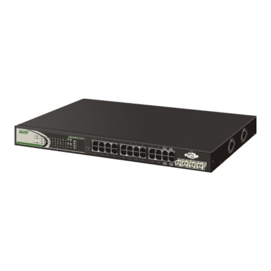
POEGEM24T4SFP User Manual 1.4. Full View of POEGEM24T4SFP Figure 1.1 1.4.1. User Interfaces on the Front Panel (Button, LEDs and Plugs) Gigabit Ethernet POE Port Port Status Indication LEDs RS-232 DB-9 Connector Power Indication LED RESET Button: RESET button is used SFP Fibre Port to reset the Figure 1.2 Front view of POEGEM24T4SFP 13 ... -
Page 14: Ac Power Socket On The Rear Panel
POEGEM24T4SFP User Manual Led Indicators LED Color Function System LED POWER Green Lit when +5V DC power is on 10/100/1000Ethernet TP Port 1 to 24 LED Lit when connection with remote device is good LINK/ACT Green Blinks when any traffic is present Off when cable connection is not good Lit green when 1000Mbps speed is active Green/ Lit amber when 100Mbps speed is active 10/100/1000Mbps Amber Off when 10Mbps speed is active 1000SX/LX Gigabit Fibre Port 21 – 24 LED Lit when connection with the remote device is good SFP(LINK/ACT) Green Blinks when any traffic is present Off when module connection is not good POE LED Lit when connection with POE Power is enabled POE Green Blinks when POE Power is present Off when POE Power is inactive ... -
Page 15: Overview Of The Optional Sfp Modules
POEGEM24T4SFP User Manual 1.5. Overview of the Optional SFP modules With the POEGEM24T4SFP switch, the SFP ports are paired with RJ‐45 copper ports 21 to 24. Only one of any given paired port can be used. In this manner, these paired ports can be seen as ‘Dual Media’ ports that support 10/100/1000Mbps or 1000Mbps fibre via the SFP interfaces. Optional 1000Mbps mini‐GBIC fibre transceiver modules can be used for high‐speed uplink connections to fibre backbones or servers, when installed in the SFP ports. A range of optional Alloy mini‐GBIC modules are available: Alloy Part No. Description 1000Mbps, mini‐GBIC, Copper, 100metres MGBIC‐T 1000Mbps multimode 1000Base‐SX, 850nm, max. range 500m MGBIC‐MLC 1000Mbps single mode 1000Base‐LX, 1310nm, max. range 10Km MGBIC‐SLC10 1000Mbps single mode 1000Base‐LHX, 1310nm, max. range 40Km MGBIC‐SLC4013 1000Mbps single mode 1000Base‐LHX, 1550nm, max. range 40Km MGBIC‐SLC4015 1000Mbps single mode 1000Base‐ZX, 1550nm, max. range 70Km MGBIC‐SLC70 1000Mbps single mode 1000Base‐EZX, 1550nm, max. range 120Km MGBIC‐SLC120 1000Mbps single mode 1000Base‐EZX, 1550nm, max. range 200Km MGBIC‐SLC200 1000Mbps WDM single mode/single fibre 1310nm, max. range 20Km MGBIC‐WDMS3.20 1000Mbps WDM single mode/single fibre 1550nm, max. range 20Km MGBIC‐WDMS3.20 1000Mbps WDM single mode/single fibre 1310nm, max. range 40Km MGBIC‐WDMS3.40 1000Mbps WDM single mode/single fibre 1550nm, max. range 40Km MGBIC‐WDMS3.40 1000Mbps CWDM single mode/single fibre 1470nm – 1610nm, max. range MGBIC‐CWDM‐40 40Km 1000Mbps CWDM single mode/single fibre 1470nm – 1610nm, max. range MGBIC‐CWDM‐70 70Km ... - Page 16 POEGEM24T4SFP User Manual regarding compatibility, please contact the supplier of your mini‐GBIC product. * The information given in the table above is current at time of publication; availability of individual Alloy mini‐GBIC modules may vary over time. Fig. 1.6 Front View of 1000Base-LX Fig. 1.5 Front View of 1000Base‐ WDM LC, SFP Fibre Transceiver SX/LX LC, SFP Fibre Transceiver 16 ...
-
Page 17: Installation
POEGEM24T4SFP User Manual 2. Installation 2.1. Starting the POEGEM24T4SFP SNMP Managed POE Switch This section provides a quick start guide for: • Hardware and Cable Installation • Management Station Installation • Software booting and configuration 2.1.1. Hardware and Cable Installation Please Note: ⇒ Wear a grounding strap to avoid damaging the switch with electrostatic discharge ⇒ Be sure that the power switch is in the ‘OFF’ position before you insert the power cord • Installing Optional SFP Mini‐GBIC Modules SFP port Mini-GBIC module Fig. 2.1: Installation of optional SFP mini‐GBIC modules • Connecting the SFP Mini‐GBIC Module to the Chassis: The optional SFP Mini‐GBIC modules are hot‐swappable, so you can plug or unplug them while the power is applied to the switch. 1. Verify that the mini‐GBIC module is compatible with the SFP port on the switch (for example, some switch manufacturers design their mini‐GBIC modules to be operable only in their branded devices). 2. Verify that the type of mini‐GBIC you have selected for use will be compatible with the type of fibre optic cable that is to be used. 3. Verify that the type of mini‐GBIC you have selected for use will be compatible with the ... - Page 18 POEGEM24T4SFP User Manual • Copper Ports ‐ Cable Installation Please Note: ⇒ The RJ‐45 ports on the Alloy POEGEM24T4SFP Switch supports MDI/MDI‐X auto‐crossover functionality. This enables use of either straight‐through or crossover UTP cable types; the RJ‐45 ports will automatically be configured to suit the characteristics of the device at the remote end of the link. ⇒ The RJ‐45 ports on the Alloy POEGEM24T4SFP Switch support Nway auto‐negotiation; the ports will automatically be configured to be compatible with the speed and duplex settings of the device at the remote end of the link. ⇒ The minimum grade of cable for use with the switch is Cat. 5 grade UTP or STP. Higher grades of UTP/STP cable may also be used to connect to the copper RJ‐45 ports. 1. Depress the clip on the RJ‐45 connector and push into the RJ‐45 port. Release connector and ensure that the cable connector is securely locked into the RJ‐45 port. 2. Repeat the above steps, as needed, for each RJ‐45 port to be connected. • Power On Please Note: ⇒ The Alloy Switch uses a 100‐240 VAC, 50‐60 Hz power supply. The power supply POEGEM24T4SFP will automatically convert your local AC power source to DC power for use by the switch. 1. Ensure that the power switch is turned off before connecting mains power. 2. Connect the power cord supplied with the switch to your nearest mains outlet. 3. Connect the other end of the power cord into the IEC power port on the switch. 4. Lock the power cable into place using the power cable clamp mounted on the IEC power port. 5. Turn the switch on. ...
-
Page 19: Cabling Requirements
POEGEM24T4SFP User Manual 2.1.2. Cabling Requirements To help ensure a successful installation and keep network performance at optimum levels, take care to use Cat.5e grade or higher cabling. Ensure that stranded core UTP cable, if used, runs for no more than 10 metres, and that solid core runs for a maximum of 100 metres. Poor cabling is the most common cause for network dropouts or poor performance. 2.1.2.1. Cabling Requirements for UTP Ports • For Ethernet copper network connections, the UTP cable used must be Cat. 3 grade as a minimum, with a maximum length of 100 metres • For Fast Ethernet copper network connections, the UTP cable used must be Cat. 5 grade as a minimum, with a maximum length of 100 metres • For Gigabit Ethernet copper network connection, UTP cable used must be Cat.5 grade or higher, with a maximum length of 100 metres. Cat.5e grade UTP cable is recommended. 2.1.2.2. Cabling Requirements for 1000SX/LX/ZX SFP Modules There are two categories of fibre optic cable ‐ multimode (MM) and single mode (SM). The later is categorised into several classes by the distance it supports. These are SX, LX, LHX, ZX and EZX. The majority of mini‐GBIC modules available use a LC type connector. The connector types used currently on Alloy mini‐GBIC modules are LC and WDM SC, for the following module types: Gigabit Fibre with multimode LC SFP mini‐GBIC modules • • Gigabit Fibre with single mode LC mini‐GBIC modules • Gigabit Fibre with single mode/single core WDM SC 1310nm SFP mini‐GBIC modules Gigabit Fibre with single mode/single core WDM SC 1550nm SFP mini‐GBIC modules • The following table lists the types of fibre optic cable that are supported by SFP mini‐GBIC modules installed in Alloy POEGEM24T4SFP. Other cable types not listed here may be supported; please contact the supplier of your switch for details. Multimode Fibre Cable and Modal Bandwidth Multimode 2.5/125μm Multimode 50/125μm IEEE 802.3z Gigabit Ethernet 1000SX Modal ... -
Page 20: Management Options Available With The Poegem24T4Sfp
POEGEM24T4SFP User Manual Please Note: ⇒ Further information can be found in section 1.5 ⇒ All figures denoting the range a given cable type can achieve must be treated as maximum values. A number of variables can limit the actual range that can be achieved – grade of cable used, quality of cable, and presence of joins in cable runs, for example 2.1.3. Management options available with the POEGEM24T4SFP The POEGEM24T4SFP supports multiple management options to allow administrators to quickly configure and monitor the switch and network performance. There are four management options available including RS‐232 console, Command Line Interface (CLI), SNMP or via the built in Web Management. The following procedures will briefly describe how each method can be performed and will also be discussed in more detail later in this manual. Section 2‐1‐3‐1: Configuring the POEGEM24T4SFP through the RS‐232 serial port. Section 2‐1‐3‐2: Configuring the POEGEM24T4SFP through the Ethernet port. 2.1.3.1. Configuring the POEGEM24T4SFP through the RS232 serial port When configuring the POEGEM24T4SFP via the RS‐232 console please connect the switch via the provided serial cable to a DCE device such as a PC. Once you have connection run a terminal emulation program such as Hyper Terminal. When connecting to the switch please use the serial settings of the switch to create the connection, the default settings are below: Baud Rate: 115200 Data Bits: 8 ... - Page 21 POEGEM24T4SFP User Manual To set or change the default IP address of the switch via the console port, please follow the steps below: 1. Log into the switch via hyper terminal using the above settings. Fig. 2.2 2. Type IP and press Enter to enter the IP configuration mode. 3. Type set ip “IP Address” “Subnet Mask” “Gateway” where “IP Address” is the IP address of the switch, “Subnet Mask” is the subnet mask of the switch and “Gateway” is the gateway address of the switch, then press Enter. 4. Type save start to save the new switch configuration as the startup configuration for the switch. 5. Type logout to exit the switches management. Fig. 2.3 21 ...
-
Page 22: Configuring The Poegem24T4Sfp Through The Ethernet Port
POEGEM24T4SFP User Manual 2.1.3.2. Configuring the POEGEM24T4SFP through the Ethernet Port There are three different methods of configuring the POEGEM24T4SFP switch through the Ethernet Port. They are CLI, Web Browser and via SNMP Management Software. We will not cover SNMP management in this manual as it will vary depending on the Network Management Software that is being used. Note: MIB files can be located for each switch on the CD‐ROM, which can then be used with your Network Management Software. The default IP Address, Subnet Mask and Gateway addresses are shown below: IP Address: 192.168.1.1 Subnet Mask: 255.255.255.0 Gateway: 192.168.1.254 To be able to communicate with the switch via the Ethernet port you will need to ensure that your computer has an IP Address in the same subnet range. Eg. IP: 192.168.1.5 Subnet Mask: 255.255.255.0 If using the web management, open a web browser and enter the default IP Address of the switch in to the address bar. You will now be prompted to log in to the switch, the default username and password is shown below: Username: admin Password: admin Fig. 2.4 Note: The web management configuration will be covered in detail in Chapter 3. 22 ... - Page 23 POEGEM24T4SFP User Manual If using the CLI open a command prompt and create a telnet session to the default IP Address of the switch. You will now be prompted to log in to the switch, the default username and password is shown below: Username: admin Password: admin Fig. 2.5 Note: The CLI configuration will be covered in detail in Chapter 4. 23 ...
-
Page 24: Operation Of Web Based Management
POEGEM24T4SFP User Manual 3. Operation of Web based Management The following chapter allows the administrator to monitor and manage the POEGEM24T4SFP through the web management interface. Management functionality such as Port Based and 802.1q VLAN, Port Aggregation (Trunking), QoS, ACL, Spanning tree, Port configuration and much more can all be configured quickly and easily via any port of the POEGEM24T4SFP. To access the web management of the POEGEM24T4SFP open up a web browser such as Internet Explorer or Mozilla Firefox and enter the default IP address in to the address bar. The default network settings for the POEGEM24T4SFP are shown below: IP Address: 192.168.1.1 Subnet Mask: 255.255.255.0 Gateway: 192.168.1.254 Username: admin Password: admin Once you have entered the IP address of the POEGEM24T4SFP in to a web browser you will be prompted with a login screen where you will need to enter a valid username and password to gain access to the switch. The default username and password are shown above. The POEGEM24T4SFP only allows one administrator to configure the switch at one time. If another user has logged in to the switch with the administrator credentials then only the first admin logged in will be able to configure the switch, the other admin will only be able to monitor the switch. Other uses can also be created to gain access to the switch for monitoring purposes only. In total only three users can have access to the web management at any one time. If you forget your username and password you will need to click on the “Forgot Password” link on the login screen. The system will now display the serial number of the unit. Make a copy of the serial number and contact Alloy Computer Products. We will then give you a temporary username and password to access your switch. This username and password can only be used once! Please ensure after accessing the switch, that you change your PASSWORD straight away! Fig. 3.1 24 ... -
Page 25: Web Management Home Overview
POEGEM24T4SFP User Manual 3.1. Web Management Home Overview Once you have entered a valid username and password and logged in to the switch, the System Information page will be displayed, this is the default page, it will be displayed every time that you log in to the switch. The System Information page gives you all relevant information regarding the switch including, Model Name, System Description, Location, Contact, Device Name, System Up Time, Current Time, BIOS Version, Firmware Version, Hardware‐Mechanical Version, Serial Number, Host IP Address, Host MAC Address, Device Port, RAM Size and Flash Size. Fig. 3.2 25 ... - Page 26 POEGEM24T4SFP User Manual ‐ System Information Page Layout At the top of the page, there is a picture of the front panel of the switch. The picture displays the port status of each of the ports on the switch. If the port is green this tells us that the port has an active connection, if the port is black then no link is present. You can then click on each of the ports to give you basic information. Fig. 3.3 As you can see from the image above, when you click on a particular port, basic information for that port will be displayed. At the top right corner of the main page is a drop down box that allows the administrator to enable and set the time out value for the Auto Logout function. If the switches Auto‐Logout time is set to 3 minutes, after 3 minutes of no activity the switch will automatically log the user out of the web interface. The Auto Logout function can also be turned off. At the left hand side of the screen is the main menu tree. This menu is used to navigate your way around the switches web interface. 26 ...
-
Page 27: System
POEGEM24T4SFP User Manual 3.2. System 3.2.1 System Information The System Information page gives you all relevant information regarding the switch including, Model Name, System Description, Location, Contact, Device Name, System Up Time, Current Time, BIOS Version, Firmware Version, Hardware‐Mechanical Version, Serial Number, Host IP Address, Host MAC Address, Device Port, RAM Size and Flash Size. Fig. 3.4 Function Name: System Information Function Description: Shows the basic system information Parameter Description: Model Name: The model name of the device. (Read Only) System Description: Gives you a description of the switch. (Read Only) Location: Specify a descriptive location name. Location name can be up to 36 Alphanumeric Characters long. Click the <save> button to update. (Read/Write) Contact: Specify the System Administrator. Contact name can be up to 36 Alphanumeric Characters long. Click the <save> button to update. (Read/Write) 27 ... - Page 28 POEGEM24T4SFP User Manual Device Name: Specify a descriptive device name for the switch. Location name can be up to 36 Alphanumeric Characters long. Click the <save> button to update. (Read/Write) System Up Time: The time accumulated since last power up. Format is Day, Hour, Minute, Second. (Read Only) Current Time: Shows the system time of the switch. Format is Day of week, Month, Day, Hours, Minutes, Seconds, Year. Eg Mon Jan 16 3:46:49 2006 (Read Only) BIOS Version: The version of the BIOS in the switch. (Read Only) Firmware Version: The firmware version in the switch. (Read Only) Hardware‐Mechanical Version: The hardware‐mechanical version of the switch. (Read Only) Serial Number: The serial number assigned to the switch. (Read Only) Host IP Address: The IP Address of the switch. (Read Only) ...
-
Page 29: Account
POEGEM24T4SFP User Manual 3.2.2. Account The account configuration is used to create or modify guest and administrator accounts. The POEGEM24T4SFP allows the administrator to create up to 4 guest accounts, accounts can only be created by the administrator. When a Guest user logs in to the switch they will not be able to modify any parameters, they just have read only rights to the switch. A Guest user can log in to the switch and change their own password, but will not be able to modify any other accounts. The Guest account is purely created for monitoring purposes only. Administrators have the ability to delete accounts and also change the username and passwords of each account. The Administrator account can’t be deleted. Fig. 3.5 Function Name: Account Configuration Function Description: Create and Modify Administrator and Guest accounts. Parameter Description: Create New: Click the Create New button to create a new guest account. Edit: Select the account that you want to edit and click the Edit button. Delete: Select the account that you want to delete and click the Delete button. Authorisation: Specifies what rights the user has. Only Administrator and Guest accounts can be created. Username: 29 ... - Page 30 POEGEM24T4SFP User Manual Please enter a username for the administrator or guest account, a maximum of 15 alphanumeric characters only. Password: Please enter a password for the administrator or guest account, a maximum of 15 alphanumeric characters only. Confirm Password: Please confirm the password. 30 ...
-
Page 31: Time
POEGEM24T4SFP User Manual 3.2.3. Time The POEGEM24T4SFP provides two methods to keep the switches time settings correct, they are via manual input and via a Time Server on the internet. If you are manually entering your time settings enter the “Year”, “Month”, “Day, “Hour”, “Minute” and “Seconds” in to the space provided. If you enter a number that is invalid, for instance you enter 61 in the seconds field it will be rounded down to the nearest valid number, in this case 59. If you are using NTP (Network Time Protocol) there are four built in Internet Time Servers that you can use, or there is a space provided where you can enter a particular Time Server address. When using NTP you will also need to specify what time zone you are presently located in. The Time Zone is Greenwich‐centered which uses the expression form of GMT +/‐ xx hours. Fig. 3.6 Function Name: System Time Setting Function Description: Enter a manual system time or synchronise the POEGEM24T4SFP’s time with an available Internet Time Server. Daylight Saving time adjustment is also supported for different locations. Parameter Description: Current Time: Shows the current system time. Manual: A manual time can be set in to the switch here. Enter the Year, Month, Day, Hour, Minute and Seconds in to the spaces provided. The valid figures 31 ... - Page 32 POEGEM24T4SFP User Manual for the parameters Year, Month, Day, Hour, Minute and Seconds are >= 2000, 1 – 12, 1 – 31, 0 – 23, 0 – 59, respectively. Once you have entered the correct time click the <apply> button to update. Default: Year 2000, Month = 1, Day = 1, Hour = 0, Minute = 0, Second = 0 NTP: NTP is used to sync the network time with a time server on the internet based on the Greenwich Mean Time (GMT). Once the user has selected one of the built in time servers or entered a manual time server and selected the correct time zone click the <apply> button to update. The switch will now sync with the selected time server, however this syncronisation does not occur periodically if the time does become out of sync for some unknown reason the administrator will manually have to click the apply button again to re‐sync with the time server. The Time Zone is an offset time of the GMT. The switch supports a configurable time zone from ‐12 to +13 hours in increments of 1 hour. Default: +8 hours Daylight Savings: Daylight Savings can be configured from ‐5 ~ +5 hours in increments of 1 hour. If your location has adopted daylight savings please enter the appropriate value in the daylight savings drop down box. If your area does have daylight savings you will need to enter a starting and ending date of the daylight savings period. Once the date passes the starting date of the daylight savings settings the switches time will be adjusted by the amount of hours entered in the drop down box. Click the <apply> button to update. Default: 0 Default values for starting and ending date: Start: Month = 1, Day = 1, Hour = 0 End: Month = 1, Day = 1, Hour = 0 32 ...
-
Page 33: Ip Configuration
POEGEM24T4SFP User Manual 3.2.4. IP Configuration The IP configuration is used to set the IP settings in the switch. The POEGEM24T4SFP supports either a static IP address allocated to them via the system administrator or can be assigned an IP address dynamically from a DHCP server on your network. The IP address is used to gain access to the management functionality of the switch. Fig. 3.7 Function Name: IP Configuration Function Description: Is used to set the IP Address, Subnet Mask, Default Gateway and DNS settings for the switch Parameter Description: DHCP Setting: The POEGEM24T4SFP supports DHCP (Dynamic Host Configuration Protocol) Client which is used to receive an IP Address from a DHCP Server running on your network. By Default the DHCP Client is disabled and a Static IP Address has been allocated to the POEGEM24T4SFP. If Enabled the switch will receive an IP Address from an existing DHCP Server on your network. If Disabled you will need to allocate an IP Address in the spaces provided. Click the <apply> button to update. Default: Disabled IP Address: If the DHCP settings are set to Disable you will need to set an IP Address for the switch. Enter the required IP Address in the space provided. Click the <apply> button to update. Default: 192.168.1.1 33 ... - Page 34 POEGEM24T4SFP User Manual Subnet Mask: You will also need to specify a Subnet Mask to be used on your network. Enter the required Subnet Mask in the space provided. Click the <apply> button to update. Default: 255.255.255.0 Default Gateway: The Default Gateway is used in routed networks to determine the next hop for all non local destinations. Enter the required Default Gateway in the space provided. Click the <apply> button to update. Default: 192.168.1.254 DNS: DNS (Domain Name Server) is used to translate between Host Names and IP addresses. If DHCP has been enabled the switch will receive a DNS IP Address dynamically from the DHCP Server. If you are not using DHCP you will need to set a DNS address in the switch. A DNS Server address should be given to you from your ISP. Enter the required DNS Server in the space provided. Click the <apply> button to update. Default: 0.0.0.0 34 ...
-
Page 35: Loop Detection
POEGEM24T4SFP User Manual 3.2.5. Loop Detection The Loop Detection function in the POEGEM24T4SFP is a basic function to eliminate loops on your network. If the switch receives its own MAC address on one or many of its ports, that port will become locked. This port will remain locked until the loop has been removed and the switches port has been unlocked. Fig. 3.8 Function Name: Loop Detection Function Description: Detects and eliminates loops on the switch Parameter Description: Port No: Displays the port numbers of the switch. (1‐16 or 1‐24) Detection Port: To enable loop detection on a specific port on the switch tick the corresponding check box. Click the <apply> button to update. Locked Port: If a loop does occur on the switch and the port is enabled to support the loop detection, the port will become locked. Tick the corresponding check box. Click the <Resume> button to unlock the port. 35 ... -
Page 36: Management Policy
POEGEM24T4SFP User Manual 3.2.6. Management Policy The Management Policy is used to implement security rules based on what type of management access a certain user has. The user management can be locked down so that only users that have a valid IP address in a predetermined range can access the switches management interfaces. Rules can also be created to allow access to management from certain switch ports only. E.g. only port 5 has access to the switches management. Rules can then be broken down even further to allow particular management access to these IP Ranges or Ports. We can specify whether we want to allow or deny access to the Web Management, Telnet or SNMP access. Fig. 3.9 Fig. 3.10 36 ... - Page 37 POEGEM24T4SFP User Manual Function Name: Management Policy Function Description: Create rules based access to the management features of the POEGEM24T4SFP. Parameter Description: Add: To add a new management policy click on the Add button. Delete: Select a rule from the list and click the Delete button to remove that rule. Name: Please enter a descriptive name for the Rule. IP Range: If you wish to lock the management down to a particular IP range please select the Custom radio button and enter the IP range in the space provided. Otherwise select the Any radio button. Incoming Port: If you want to lock the management interface access down to certain ports on your switch please select the Custom radio button and tick the required ports which will allow/deny access to the management. Otherwise select the Any radio button. Access Type: After you have determined what physical access has been granted or denied to the management you now need to specify what management access is allowed. If you wish to allow/deny a particular type of access, select the Custom radio button and select the type of access required, HTTP, Telnet or SNMP. Otherwise select the Any radio button. Action: ...
-
Page 38: System Log
POEGEM24T4SFP User Manual 3.2.7. System Log The POEGEM24T4SFP will log certain events when they occur. For example if the device was rebooted a log entry will be created. Other events that may be logged are link down, link up, logout, login and other information. Fig. 3.11 Function Name: System Log Function Description: Displays a log of events that have taken place. Parameter Description: No: Displays the order of events that have occurred. Time: Displays the time the event occurred. Desc: Displays a description of the event that has taken place. Clear: Click the <Clear> to clear all events in the list. 38 ... -
Page 39: Virtual Stack
POEGEM24T4SFP User Manual 3.2.8. Virtual Stack The POEGEM24T4SFP allows the administrator to administer multiple switches from a single IP Address. Each switch will have its own IP Address and will be set up as a slave or a master. Only a single switch can be set up as the master and all other switches will be slaves. The administrator can log into the IP Address of the master switch and administer all slave switches from within the master switch. Up to 16 devices can be used per group. Fig. 3.12 Function Name: Virtual Stack Function Description: Used to configure master/slave settings for the management of the switch. Parameter Description: State: Used to enable or disable the virtual stacking function. Role: Used to select the Master or Slave role of the switch.. Group ID: Used to determine what switch will be managed via the master switch. All switches must have the same group ID. Apply: Click <Apply> to save any changes made. 39 ... -
Page 40: Port
POEGEM24T4SFP User Manual 3.3. Port 3.3.1 Configuration The Port Configuration section allows the administrator to Enable or Disable a port, turn auto negotiation on or off for a particular port and also force the speed and duplex settings of each port. The administrator can also Enable or Disable the flow control settings, set the maximum frame size supported by that port and determine what to do with excessive collisions on each port. Fig. 3.13 Function Name: Port Configuration Function Description: Allows the Administrator to manually enable or disable a port, disable auto‐negotiation and force the speed of a port and also allow the flow control to be enabled or disabled for each port. The maximum frame size and collision settings can also be set for each port. Parameter Description: Port No: Displays the port number of each port on the switch. Media: States the media type of the port; TP or SFP Speed: Used to Enable or Disable the port as well as set the speed and duplex settings of each port. Available options are Disabled, Auto, 1Gbps FDX, 100Mbps FDX, 100Mbps 40 ... - Page 41 POEGEM24T4SFP User Manual HDX, 10Mbps FDX and 10Mbps HDX on the TP Port and Auto and 1Gbps FDX on the SFP Ports. Default: Auto Flow Control: Shows the port’s flow control status, the POEGEM24T4SFP supports both Backpressure flow control for Half Duplex and Pause flow control for Full Duplex. Select the appropriate flow control setting from the drop down box. Selections include SYM (Symmetrical), ASYM (Asymmetrical), SYM and ASYM and Disabled. Default: SYM Maximum Frame: Used to set the maximum frame size for each port, available values are 1518 – 9600. Default: 9600 Excessive Collision Mode: When running in half duplex mode traffic collision may occur. There are two options available to handle the collision traffic: Discard ‐ If excessive collisions occur packets will be discarded, based on IEEE 802.3 half duplex flow control operation. Restart – Rather than drop the frames after excessive collisions the switch can restart the backoff sequence. This violates the IEEE 802.3 standard but can be useful for particular circumstances. Default: Discard Description: Enter a description of the port. 41 ...
-
Page 42: Port Status
POEGEM24T4SFP User Manual 3.3.2. Port Status The Port Status section allows the administrator to view the current status of each port. The port status screen tells us the type of media being used, whether the link is active or not, whether the port is active or not, if it is using auto negotiation, what speed the port is running at and whether flow control is enabled. Fig. 3.14 Function Name: Port Status Function Description: Reports the current Status of each port, if the state of a port changes the status screen will refresh every 5 seconds. Parameter Description: Port No: Displays every port on the switch Link: Will tell you whether the ports link state is Up or Down, Up being active and Down being inactive. Speed: Displays the Speed and Duplex settings of each port, speed settings can either be 10Mbps, 100Mbps or 1000Mbps for Copper supporting both Half and Full Duplex or 1000Mbps Full Duplex for Fibre. If the port does not have an active link then Down will be displayed. 42 ... - Page 43 POEGEM24T4SFP User Manual Flow Control: Shows the port’s flow control status, the POEGEM24T4SFP supports both, Flow Control for TX and RX. Description: Displays the description of the port. If you have a valid link on a Fibre port, you can see more detailed information for that port by clicking on the port number in the Port Status screen. Fig. 3.15 Parameter Description for all Fibre Ports: Connector Type: Displays the connector type for that port, for instance, UTP, SC, ST, LC and so on. Fibre Type: Displays the type of fibre being used, for instance, Multimode or Single‐Mode. TX Central Wavelength: Displays the fibre optical transmitting central wavelength, for instance, 850nm, 1310nm, 1550nm and so on. Baud Rate: Displays the maximum speed the SFP module supports. Vendor OUI: 43 ...
- Page 44 POEGEM24T4SFP User Manual Displays the manufacturers OUI code which is assigned by the IEEE. Vendor Name: Displays the company name of the SFP module manufacturer. Vendor PN: Displays the part number of the SFP module. Vendor Rev: Displays the revision number of the SFP module. Vendor SN: Displays the serial number of the SFP module. Date Code: Displays the date the SFP module was manufactured. Temperature: Displays the current temperature of the SFP module. Vcc: Shows the current working voltage of the SFP module. ...
-
Page 45: Simple Counter
POEGEM24T4SFP User Manual 3.3.3. Simple Counter The Simple Counter section allows the administrator to view information regarding the amount of data that is being passed through a particular port whether the packets are good or bad. Fig. 3.15 shows you a screen shot of the simple counter screen, as you can see from the image all ports on the switch are displayed at one time. If the amount of data being displayed on the screen is more that 12 digits long, the counter will be reset back to zero and continue on. Fig. 3.16 Function Name: Simple Counter Function Description: Displays the amount of data that has passed through the switches port including: TX Packet, RX Packet, TX Byte, RX Byte, TX Errors, RX Errors, TX Drops and RX Drops. Parameter Description: Port No: Displays every port on the switch Transmit Packet: Displays the total amount of packets transmitted. Receive Packet: Displays the total amount of packets received. Transmit Byte: 45 ... - Page 46 POEGEM24T4SFP User Manual Displays the total transmitted bytes. Receive Byte: Displays the total received bytes. Transmit Errors: Displays the total amount of transmitted errors Receive Errors: Displays the total amount of received errors. Transmit Drops: Displays the total amount of transmitted packets that were dropped. Receive Drops: Displays the total amount of received packets that were dropped. Auto Refresh: Tick the check box to enable Auto updating of port status. Refresh: Press the refresh button to update the status page manually. Clear: The clear button is located at the top right hand side of the screen and is used to ...
-
Page 47: Detail Counter
POEGEM24T4SFP User Manual 3.3.4. Detail Counter The Detail Counter section allows the administrator to view information regarding the amount of data that is being passed through a particular port whether the packets are good or bad. Fig. 3‐17 shows you a screen shot of the detail counter screen, unlike the simple counter screen the detail counter screen will only display the statistics of one port at a time. If you wish to view a particular ports statistics select the port from the drop down box provided. If the amount of data being displayed on the screen is more that 12 digits long, the counter will be reset back to zero and continue on. Fig. 3.17 Function Name: Detail Counter Function Description: Displays in detail the amount of data that has passed through each of the switches ports. Parameter Description: RX Packets: Displays the total amount of packets received. RX Octets: Displays the total amount of received bytes. RX Unicast: Displays the total amount of unicast packets received. RX Multicast: Displays the total amount of multicast packets received. 47 ... - Page 48 POEGEM24T4SFP User Manual RX Broadcast: Displays the total amount of broadcast packets received. RX Pause: Displays the total amount of pause packets received. TX Packets: Displays the total amount of packets transmitted. TX Octets: Displays the total amount of transmitted bytes. TX Unicast: Displays the total amount of unicast packets transmitted. TX Multicast: Displays the total amount of multicast packets transmitted. TX Broadcast: Displays the total amount of broadcast packets transmitted. TX Pause: Displays the total amount of pause packets transmitted. RX 64 Bytes: ...
- Page 49 POEGEM24T4SFP User Manual TX 128 ~ 255 Bytes: Displays the total amount of 128 ~ 255 byte frames transmitted. TX 256 ~ 511 Bytes: Displays the total amount of 256 ~ 511 byte frames transmitted. TX 512 ~ 1023 Bytes: Displays the total amount of 512 ~ 1023 byte frames transmitted. TX 1024 ~ 1526 Bytes: Displays the total amount of 1024 ~ 1526 byte frames transmitted. TX 1527 Bytes: Displays the total amount of 1527 byte or larger frames transmitted. RX Drops: Displays the total amount of frames dropped due to the receive buffer being full. RX CRC/Alignment: Displays the total amount of Alignment and CRC error packets received. RX Undersize: Displays the total amount of short frames (<64 bytes) received with valid CRC. ...
-
Page 50: Power Saving
POEGEM24T4SFP User Manual 3.3.5. Power Saving The power saving functions allows the switch to disable ports to reduce power consumption and reduce the power needed to send data across the cable depending on the cable length. The switch uses to methods to save power, these are called “ActiPHY Power Management” and “Perfect Reach Power Management”. Fig. 3.18 Function Name: Power Save Function Description: Used to reduce power consumption of the switch. Parameter Description: Port: The physical port of the switch. Power Saving: Tick the check box to enable Power Saving function on this port. Select\Unselect All: Tick this box to select or unselect all ports. 50 ... -
Page 51: Vlan
POEGEM24T4SFP User Manual 3.4. VLAN 3.4.1. VLAN Mode The POEGEM24T4SFP supports both 802.1q Tagged based VLAN’s and Port‐based VLAN’s. VLAN’s are used to logically separate your network in to smaller more defined networks. VLAN’s help to reduce broadcast traffic across your network as all broadcast traffic will be limited to the VLAN group in which it belongs. A typical example of where a VLAN could be used is in a school environment where the teacher and student networks must be kept separate. The switch supports up to 256 active VLAN entries and a VLAN ID ranging from 1 – 4096. Fig. 3.19 Function Name: VLAN Mode Function Description: The POEGEM24T4SFP supports 2 different VLAN modes: Port‐Based and Tag‐based. Select the desired VALN mode from the drop down box and click the Apply button. Changes will take effect immediately. Parameter Description: Port‐based: Port‐based VLAN’s are as it states defined by each port. Ports are configured in to logical groups allowing data to be sent to and from any port that belongs to a particular group. If a port belongs to VLAN group 1 and another port belongs to VLAN group 2 these ports will not be able to communicate with each other. Ports that belong to the same group can communicate. Ports can also belong to multiple ... - Page 52 POEGEM24T4SFP User Manual groups. The switch has support for up to 24 port‐based VLAN groups. Tag‐based: Tag‐based VLAN’s identify members by its VID. A VID can be applied to a packet from a host machine that supports 802.1q or from the switch itself when a packet is sent from the switch. Ingress and Egress rules can also be applied to each port to identify how a packet is handled. The switch will accept both tagged and un‐tagged packets depending on the ingress rules that have been defined. Rules can be created to only allow incoming packets to be tagged, if they are not tagged they will be dropped. Each tag‐based VLAN you build must have a VLAN name and VLAN ID. Valid VLAN ID’s range from 1 – 4094. The maximum number of tag‐based VLAN groups that can be created is 4094. 52 ...
-
Page 53: Tag-Based Group
POEGEM24T4SFP User Manual 3.4.2. Tagbased Group Fig. 3.20 Function Name: Tag‐based Group Function Description: Shows information of the existing tag‐based VLAN groups, the administrator can also Add, Delete and Edit VLAN’s using the function buttons provided. Parameter Description: VLAN Name: Is the name of the VLAN group defined by the Administrator. Valid characters that can be used are A – Z, a – z and 0 – 9. Special characters are not allowed and a total of 15 characters are supported. VID: VID is the VLAN Identifier. Each tag‐based VLAN group must have a unique VID. Port Members: Displays the currents ports configured for each VLAN. IGMP Proxy: IGMP proxy enables the switch to issue IGMP host messages on behalf of hosts that ... - Page 54 POEGEM24T4SFP User Manual Private VLAN: A private VLAN contains switch ports that cannot communicate with each other but can access another networks. These ports are called private ports. Each private VLAN contains one or more private ports, and a single uplink port or uplink aggregation group. Delete: Once you have created a VLAN, a check box will appear on the left hand side. Tick the check box and press the <delete> button to remove the VLAN. The default VLAN cannot be deleted. Add New VLAN: Used to create a new VLAN group; Fig. 3.21 Enter the required VLAN ID, and VLAN name in the spaces provided. Tick the IGMP Proxy or Private VLAN check boxes to enable these functions. Now select the ports that you wish to add to the new VLAN and press the <Apply> button to save. 54 ...
-
Page 55: Port-Based Group
POEGEM24T4SFP User Manual 3.4.3. Portbased Group Fig. 3.22 Function Name: Port‐based Group Function Description: Shows information of the existing Port‐based VLAN groups, the administrator can also Add, Delete and Edit VLAN’s using the function buttons provided. Parameter Description: VLAN Name: Is the name of the VLAN group defined by the Administrator. Valid characters that can be used are A – Z, a – z and 0 – 9. Special characters are not allowed and a total of 15 characters are supported. Group: Group is the Port‐Based VLAN group that has been created. Port Members: Displays the currents ports configured for each VLAN. Delete: Once you have created a VLAN, a check box will appear on the left hand side. Tick the check box and press the <delete> button to remove the VLAN. The default VLAN cannot be deleted. Add New VLAN: Used to create a new VLAN group; 55 ... - Page 56 POEGEM24T4SFP User Manual Fig. 3.23 Enter the required VLAN name in the space provided. Now select the ports that you wish to add to the new VLAN group and press the <Apply> button to save. 56 ...
-
Page 57: Ports
POEGEM24T4SFP User Manual 3.4.4. Ports Fig. 3.24 Function Name: Ports Function Description: The Ports section is used to configure the VID of each port. This section only applies to Tag‐ Based VLAN’s. Administrators can configure VID’s ranging from 1 to 4094, Ingress rules can also be applied to each port. Rule 1 is “forward only packets with VID matching this ports configured VID” and rule 2 is “drop untagged frame”. The Role of each port can also be ... - Page 58 POEGEM24T4SFP User Manual PVID range is 1 – 4094. Before you configure a PVID you must create a Tag‐based VLAN with the VID matching the PVID you are about to create. For example, if port x receives an untagged packet, the switch will apply the PVID of port x to this packet, the packet will then be forwarded as a tagged packet with the VID you have created. Role: This is an Egress rule for the port. Here you can select the role of the port to be Access, Trunk or Hybrid. Trunk means that all outgoing packets must carry a VLAN tag header. Access means the outgoing packets carry no VLAN tag header. If packets have double VLAN tags, one will be dropped and the other will be used. Hybrid is similar to Trunk in which both of them will tag outgoing packets. When the port is set to hybrid the outgoing packets will be untagged if the VID matches the VID configured in the Untag VID section. Untag VID: Valid range is 0 – 4094. This will only work if the Role is set to Hybrid. Double Tag: When Double Tag is enabled all packets that enter the switch whether they are tagged or untagged will be tagged with the configured VID. Therefore if a packet is already tagged this allows a second VID to be applied to the packet thus creating a Q‐ in‐Q or double tag packet. 58 ...
-
Page 59: Port Isolation
POEGEM24T4SFP User Manual 3.4.5. Port Isolation Fig. 3.25 Function Name: Port Isolation Function Description: Used to isolate ports from communicating with each other. Parameter Description: Port: Is the Port number that you want to configure. 59 ... -
Page 60: Management Vlan
POEGEM24T4SFP User Manual 3.4.6. Management VLAN Fig. 3.26 Function Name: Management VLAN Function Description: Used to assign a specific VLAN for management purposes. Only ports within the Management VLAN group can manage the switch. Parameter Description: VLAN ID: Specify the Management VLAN group. 60 ... -
Page 61: Mac
POEGEM24T4SFP User Manual 3.5. MAC 3.5.1. MAC Address Table Fig. 3.27 Function Name: MAC Address Table Function Description: This function allows the administrator to set up the processing mechanism of the MAC Table. An idle MAC address exceeding the MAC Address Age‐out Time will be removed from the MAC Table. The range of Age‐out Time is 10‐1000000 seconds, and the setup of this time will have no effect on static MAC addresses. In addition, the learning limit of the MAC maintenance is able to limit the amount of MAC addresses that each port can learn. Parameter Description: Age Time: The Age time of a MAC address will limit the amount of time the MAC will stay in the switches MAC address table. If the MAC is idle for the configured amount of time, the MAC will be dropped from the table. Default: 300 seconds Disable Automatic Aging: Disables the MAC aging timer, if enabled the MAC address will not be dropped from the MAC table automatically. 61 ... -
Page 62: Appendix B Null Modem Cable Specifications
POEGEM24T4SFP User Manual Auto: Allows the port to automatically learn MAC addresses. Disable: Disables the ability for the port to learn MAC addresses, only static MAC addresses can be configured. Secure: Disables the ability for the port to learn MAC addresses and copies the dynamic learning packets to CPU. Save: Press the save button to save MAC configuration settings. Reset: Reset the MAC address settings to default. 62 ... -
Page 63: Static Filter
POEGEM24T4SFP User Manual 3.5.2. Static Filter Fig. 3.28 Function Name: Static filter Function Description: The Static filter function is used to block certain MAC addresses to be forwarded by the switch. If a MAC address is listed in this table, all packets from that destination MAC address will be discarded. Parameter Description: MAC: Is a six byte long Ethernet hardware address and is usually expressed by hex and separated by Hythens. VID: VLAN Identifier, this will only be used when tagged VLAN’s are enabled. Alias: A name that can be assigned to a MAC address. Add: After you have entered the required information click <Add> to add the MAC into the table. Delete: Highlight the required MAC address and click <delete> to remove the MAC address. 63 ... -
Page 64: Static Forward
POEGEM24T4SFP User Manual 3.5.3. Static Forward Fig. 3.29 Function Name: Static forward Function Description: The Static forward function is used to manually add MAC addresses to the MAC table of the switch. When adding a MAC address you can allocate the port that this MAC address will belong to. All traffic destined for the MAC address will be forwarded to the configured port. Parameter Description: MAC: Is a six byte long Ethernet hardware address and is usually expressed by hex and separated by Hythens. Port: Select the Port to which the configured MAC address will belong to. VID: VLAN Identifier, this will only be used when tagged VLAN’s are enabled. Alias: A name that can be assigned to a MAC address. Add: After you have entered the required information click <Add> to add the MAC into the table. Delete: 64 ... - Page 65 POEGEM24T4SFP User Manual Highlight the required MAC address and click <delete> to remove the MAC address from the list. 65 ...
-
Page 66: Mac Alias
POEGEM24T4SFP User Manual 3.5.4. MAC Alias Fig. 3.30 Function Name: MAC Alias Function Description: The MAC Alias function is used to allocate a Name to a MAC Address. Parameter Description: MAC: Is a six byte long Ethernet hardware address and is usually expressed by hex and separated by Hythens. Alias: A name assigned to a MAC address, this can be composed of A‐Z, a‐z and 0‐9 and has a maximum length of 15 characters. Create/Edit: Once the MAC address and Alias name have been entered click the <Create/Edit> button to add to the MAC Table. Delete: Highlight the required MAC address and click <delete> to remove the MAC address from the list. 66 ... -
Page 67: Mac Table
POEGEM24T4SFP User Manual 3.5.5. MAC Table Fig. 3.31 Function Name: MAC Table Function Description: Displays both the static and dynamic MAC Addresses learned by the switch. Parameter Description: Type: Static or Dynamic. VLAN: VLAN identifier. This only applies when tag based VLAN’s are in use. MAC Address: Displays the MAC address. Port: The port the MAC address has been assigned to. Refresh: Used to refresh or update the screen. Clear: Used to clear the specific entry. Previous Page: 67 ... - Page 68 POEGEM24T4SFP User Manual Move to the previous page. Next Page: Move to the next page. 68 ...
-
Page 69: Poe
POEGEM24T4SFP User Manual 3.6. POE The POEGEM24T4SFP supports the IEEE 802.3af PoE standard for Power Injection (PSE). This injects PoE power onto the Cat5 Cable when it detects the presence of a PoE compliant device. When operating with non PoE devices the switch will shut down the power injecting circuitry and as such not cause any damage to your network devices ‐ but still allow them to run on the switch as in the case of a normal Ethernet device. The POEGEM24T4SFP uses an injection voltage of about 48VDC on pins 1, 2, 3, 6 3.6.1. Configuration Fig. 3.32 Function Name: POE Configuration Function Description: The POE Configuration screen allows the administrator to set a priority level to each of the POE ports on the switch. If the switch is using all 24 ports to supply power to PD devices and the power being drawn is too high for the switch it will need to shut down a port or ports. The port or ports that will be shut down will be determined by this priority level. Each of the ports can also disable or enable the POE function. Parameter Description: Status: Displays the mode the port is running in, this can be Normal or Active. If running in normal mode the port is ready and waiting to supply power to a connecting device. If Active is displayed the port is already supplying power to its connecting device. 69 ... - Page 70 POEGEM24T4SFP User Manual State: If the port is set to Enable the port can supply power to the connecting device. If the port is set to Disable the port will not be able to supply power. Priority: Each port of the switch can be applied a priority level of Low, Normal or High. If the switches total power limit is exceeded ports may need to be shut down. The ports that will be shut down first will be determined by the priority level given to the port. The priority order is Low, Normal and then high. If all ports have the same priority level the port with the highest port ID eg. Port number 12, will be disabled first. Power (W): The total power been drawn from each port. Current (mA): The total current supplied to the PD. Class: The Class of the PD connected to the port of the switch. 70 ...
-
Page 71: Status
POEGEM24T4SFP User Manual 3.6.2. Status Fig. 3.33 Function Name: POE Status Function Description: Display’s information regarding the status of each of the POE ports. Parameter Description: Vmain: The Voltage supplied by the POE device. Imain: The total current supplied by each of the POE ports. Pconsume: The total power supplied by each port. Power Limit: The maximum amount of power the switch can provide. (Read Only) Temperature: The temperature of the POE chipset inside the switch. Port No: The port number of each port on the switch. 71 ... - Page 72 POEGEM24T4SFP User Manual Port On: Display’s whether the port is supplying power. AC Disconnect Port Off: Port has been turned off due to the AC Disconnect function. DC Disconnect Port Off: Port has been turned off due to the DC Disconnect function. Overload Port Off: The switch will stop supplying power to the connecting device because of excessive power drain. Short Circuit Port Off: The switch will stop supplying power to the port if a short circuit is detected on the connecting device. Over Temp. Protection: The port of the switch will be disabled due to the fast transient rise in temperature to C or slow rise in temperature to 200 C. Power Management Port Off: If the total power drawn from each of the ports on the switch exceeds the switches power limit, ports will need to be disabled based on the priority given to each of the ports. 72 ...
-
Page 73: Gvrp
POEGEM24T4SFP User Manual 3.7. GVRP GVRP is an application based on Generic Attribute Registration Protocol (GARP), mainly used to automatically and dynamically maintain the group membership information of VLANs. GVRP offers a function providing VLAN registration service through a GARP application. It makes use of GARP Information Declaration (GID) to maintain the ports associated with their attribute database and GARP Information Propagation (GIP) to communicate among switches and end stations. With GID information and GIP, GVRP state machine maintain the contents of Dynamic VLAN Registration Entries for each VLAN and propagate this information to other GVRP‐aware devices to setup and update their knowledge database, the set of VLANs associated with currently active members, and through which ports these members can be reached. In GVRP Configuration function folder, there are three functions supported, including GVRP Config, GVRP Counter and GVRP Group explained below. 3.7.1. Config Fig. 3.34 Function Name: GVRP Configuration Function Description: This function is used to configure each ports GVRP operation mode, in which there are seven parameters that need to be configured. These are explained below: Parameter Description: GVRP State: This function simply allows the administrator to enable or disable the GVRP function. 73 ... - Page 74 POEGEM24T4SFP User Manual Join Time: Used to configure the Join Time in units of Centiseconds. Valid time range: 20 – 100 centiseconds Default: 20 Leave Time: Used to configure the Leave Time in units of Centiseconds. Valid time range: 60 – 300 centiseconds Default: 60 Leave All Time: A time period for the announcement that all registered devices will be de‐registered. If a new join is issued, then a registration will be kept in the switch. Valid range: 1000‐5000 unit time. Default: 1000 unit time. Default Applicant Mode: This determines the type of participant in a GVRP group, there are two types, normal participant and non‐participant. Normal: The switch participates normally in GARP protocol exchanges. Non Participant: In this mode the switch does not send or reply to any GARP messages. It just listens to messages and reacts for the received GVRP BPDU. Default Registrar Mode: This determines the type of registrar, there are three types, normal registrar, fixed registrar and forbidden registrar. Normal: The registrar responds normally to incoming GARP messages. Fixed: The registrar ignores all GARP messages and all members remain in the registered (IN) state. Forbidden: The registrar ignores all GARP messages and all members remain in the unregistered (EMPTY) state. Restricted Mode: ...
-
Page 75: Counter
POEGEM24T4SFP User Manual 3.7.2. Counter Fig. 3.35 Function Name: GVRP Counter Function Description: This function is used to monitor the GVRP actions. These are divided into received and transmitted categories. Parameter Description: Received: Total GVRP Packets: Total GVRP BPDU received by the GVRP application. Invalid GVRP Packets: Number of invalid GARP BPDU’s received by the GARP application. LeaveAll Message Packets: Number of GARP BPDU’s with Leave All message received by the GARP application. JoinEmpty Message Packets: Number of GARP BPDU with Join Empty message received by the GARP application. JoinIn Message Packets: Number of GARP BPDU with Join In message received by the GARP application. 75 ... - Page 76 POEGEM24T4SFP User Manual Leave Empty Message Packets: Number of GARP BPDU with Leave Empty message received by the GARP application. Empty Message Packets: Number of GARP BPDU with Empty message received by the GARP application. Transmitted: Total GVRP Packets: Total GVRP BPDU transmitted by the GVRP application. Invalid GVRP Packets: Number of invalid GARP BPDU’s transmitted by the GARP application. LeaveAll Message Packets: Number of GARP BPDU’s with Leave All message transmitted by the GARP application. JoinEmpty Message Packets: Number of GARP BPDU with Join Empty message transmitted by the GARP application. JoinIn Message Packets: Number of GARP BPDU with Join In message transmitted by the GARP application. Leave Empty Message Packets: Number of GARP BPDU with Leave Empty message transmitted by the GARP application. Empty Message Packets: ...
-
Page 77: Group
POEGEM24T4SFP User Manual 3.7.3. Group Fig. 3.36 Function Name: GVRP Group VLAN information Function Description: Shows the dynamic group member and their information Parameter Description: VID: VLAN Identifier. When GVRP creates a VLAN group, each group has its own VID. Valid Range: 1 – 4094 Member Port: Ports belonging to the same dynamic VLAN group. Edit Administrative Control: When a GVRP group has been created, you can use the Administrative Control function to change the Applicant and Registrar modes of the GVRP member. 77 ... -
Page 78: Qos (Quality Of Service) Configuration
POEGEM24T4SFP User Manual 3.8. QoS (Quality of Service) Configuration The POEGEM24T4SFP support four QoS queues per port with strict or weighted fair queuing scheduling. There are 24 QoS Control Lists (QCL) for advance programmable QoS classification, based on IEEE 802.1p, Ethertype, VID, IPv4/IPv6 DSCP and UDP/TCP ports and ranges. The QoS classification looks for information up to Layer 4, including IPv4 and IPv6 DSCP, IPv4 TCP/UDP port numbers, and user priority of tagged frames. This QoS classification mechanism is implemented in a QoS control list (QCL). The QoS class assigned to a frame is used throughout the device for providing queuing, scheduling, and congestion control which is guaranteed to the frame according to what was configured for that specific QoS class. The switch supports advanced memory control mechanisms providing excellent performance of all QoS classes under any traffic scenario, including jumbo frames. The ingress super priority queue allows traffic recognised as CPU traffic to be received and queued for transmission to the CPU even when all the QoS class queues are congested. 3.8.1. Ports Fig. 3.37 Function Name: Port QoS Configuration Function Description: This function is used to configure each ports QoS behaviour, four QoS queues per port with strict or weighted fair queuing is supported. There are 24 QoS Control Lists (QCL) for advanced programmable QoS classification, based on IEEE 802.1p, Ethertype, VID, IPv4/IPv6 DSCP and UDP/TCP ports and ranges. 78 ... - Page 79 POEGEM24T4SFP User Manual Parameter Description: Number of Classes: 1 / 2 / 4 classes can be used on each port. Port: Each port can be configured to use QoS. Default Class: A low, normal, medium and high priority class can be set to each port respectively. This default class is used if no QoS Control List entry matches; QCL: Up to 24 QoS Control List rules can be created, only one of these rules can be applied to each port. User Priority: The user priority value 0~7 (3 bits) is used as an index to the eight QoS class values for VLAN tagged or priority tagged frames. Queuing Mode: T here are two Scheduling Methods, Strict Priority and Weighted Fair. Default is Strict Priority. After you choose any of Scheduling Methods, please click <Apply> button to activate. Queue Weighted: T here are four queues per port and four classes weighted number (1 / 2 / 4 / 8) for each queue. A weighted number can be selected when the scheduling method is set to “Weighted Fair” mode. 79 ...
-
Page 80: Qos Control List Configuration
POEGEM24T4SFP User Manual 3.8.2. QoS Control List Configuration Fig. 3.38 Function Name: QoS Control List Configuration Function Description: The GSM Series support four QoS queues per port with strict or weighted fair queuing scheduling. There are 24 QoS Control Lists (QCL) for advanced programmable QoS classification, based on IEEE 802.1p, Ether Type, VID, IPv4/IPv6 DSCP and UDP/TCP ports and ranges. Parameter Description: Move entry up Insert an entry Edit this entry Move entry down QCE Configuration: T he QCL consists of 12 QoS Control Entries (QCEs) that are searched from the top of the list to the bottom of the list for a match. The first matching QCE determines the 80 ... - Page 81 POEGEM24T4SFP User Manual QoS classification of the frame. The QCE ordering is therefore important for the resulting QoS classification algorithm. If no matching QCE is found, the default QoS class is used in the port QoS configuration. Fig. 3.39 Fig. 3.40 Fig. 3.41 81 ...
- Page 82 POEGEM24T4SFP User Manual Fig. 3.42 Fig. 3.43 Fig. 3.44 82 ...
- Page 83 POEGEM24T4SFP User Manual Fig. 3.45 QCL#: QCL number : 1~24 QCE Type: Ethernet Type / VLAN ID / UDP/TCP Port / DSCP / ToS / Tag Priority Ethernet Type Value: The configurable range is 0x600~0xFFFF. Well known protocols already assigned EtherType values. The commonly used values in the EtherType field and corresponding protocols are listed below:...
- Page 84 POEGEM24T4SFP User Manual 0x0808 Frame Relay ARP [RFC1701] 0x6559 Raw Frame Relay [RFC1701] DRARP, Dynamic RARP. RARP, 0x8035 Reverse Address Resolution Protocol. 0x8037 Novell Netware IPX 0x809B EtherTalk (AppleTalk over Ethernet) 0x80D5 IBM SNA Services over Ethernet AARP, AppleTalk Address Resolution 0x 80F3 Protocol.
- Page 85 POEGEM24T4SFP User Manual 0x8E88 EAPOL, EAP over LAN. 0x9000 Loopback (Configuration Test Protocol) 0xFFFF reserved. VLAN ID: The configurable VID range: 1~4094 UDP/TCP Port: Select the UDP/TCP port classification method by Range or Specific. UDP/TCP Port Range: T he configurable ports range: 0~65535 You can refer to following UDP/TCP port‐numbers information. http://www.iana.org/assignments/port‐numbers UDP/TCP Port No.: The configurable specific port value: 0~65535 DSCP Value: The configurable DSCP value: 0~63 Traffic Class: Low / Normal / Medium / High 85 ...
-
Page 86: Rate Limiters
POEGEM24T4SFP User Manual 3.8.3. Rate Limiters Fig. 3.46 Function Name: Rate Limiters Function Description: Each port includes an ingress rate, and an egress rate which can limit the bandwidth of received and transmitted frames. Ingress rate or egress rate operation is controlled per port in the Rate Limit Configuration. Parameter Description: Port #: Port number. Ingress Enabled: Ingress enabled to limit ingress bandwidth by ingress rate. Ingress Rate: The configurable Ingress rate range: 500 Kbps ~ 1000000 Kbps 1 Mbps ~ 1000 Mbps Ingress Unit: There are two units for ingress enabler rate limit: kbps / Mbps Egress Enabled: 86 ... - Page 87 POEGEM24T4SFP User Manual Enable Egress to limit egress bandwidth by egress rate. Egress Rate: The configurable egress rate range: 500 Kbps ~ 1000000 Kbps 1 Mbps ~ 1000 Mbps Egress Unit: There are two units for egress rate limit: kbps / Mbps 87 ...
-
Page 88: Storm Control
POEGEM24T4SFP User Manual 3.8.4. Storm Control Fig. 3.47 Function Name: Storm Control Function Description: The POEGEM24T4SFP supports storm ingress rate control function to limit Flooded, Multicast and Broadcast Storm events. Parameter Description: Frame Type: There are three frame types that can be controlled: Flooded unicast / Multicast / Broadcast Status: Enable/Disable Selection: means enabled, means disabled Rate(pps): Refer to the following rate configurable value list, the unit is Packet Per Second (pps). 1 / 2 / 4 / 8 / 16 / 32 / 64 / 128 / 256 / 512 / 1K / 2K / 4K / 8K / 16K / 32K / 64K / 128K / 256K / 512K / 1024K 88 ... - Page 89 POEGEM24T4SFP User Manual Fig. 3.48 89 ...
-
Page 90: Wizard
POEGEM24T4SFP User Manual 3.8.5. Wizard Fig. 3.49 Function Name: Wizard Function Description: The QCL configuration Wizard is used to easily configure the QCL rules for QoS configuration. The wizard provides the typical network application rules, which can be applied quickly and easily. Parameter Description: Please select an Action: User needs to select one of the actions from the following items, then click on <Next> to finish QCL configuration: Set up Port Policies Set up Typical Network Application Rules Set up TOS Precedence Mapping Set up VLAN Tag Priority Mapping Next: Go to next step. Cancel: 90 ... - Page 91 POEGEM24T4SFP User Manual Abort current configuration, go back to previous step. Back: Back to previous screen. Fig. 3‐50 Set up Port Policies Parameter description: QCL ID: QoS Control List (QCL): 1~24 Port Member: Port Member: 1~16 Fig. 3‐51 Set up Port Policies Parameter description: Wizard Again: Click on the <Wizard Again>, to go back to QCL Configuration Wizard. 91 ...
- Page 92 POEGEM24T4SFP User Manual Finish: When you click on <Finish>, the parameters will be set according to the wizard configuration and shown on the screen, then ask you to click on <Apply> for changed parameters confirmation. Fig. 3‐52 Set up Port Policies Finish Fig. 3‐53 Set up Typical Network Application Rules Fig. 3‐54 Set up Typical Network Application Rules 92 ...
- Page 93 POEGEM24T4SFP User Manual Fig. 3‐55 Set up Typical Network Application Rules Parameter description: Audio and Video: QuickTime 4 Server / MSN Messenger Phone / Yahoo Messenger Phone / Napster / Real Audio Games: Blizzard Battlenet (Diablo2 and StarCraft) / Fighter Ace II / Quake2 / Quake3 / MSN Game Zone User Definition: Ethernet Type / VLAN ID / UDP/TCP Port / DSCP Ethernet Type Value: Type Range: 0x600~0xFFFF VLAN ID: VLAN ID Range: 1~4094 UDP/TCP Port: Two Mode: Range / Specific UDP/TCP Port Range: Port Range: 0~65535 UDP/TCP Port No.: Port Range: 0~65535 DSCP Value: DSCP Value Range: 0~63 93 ...
- Page 94 POEGEM24T4SFP User Manual Fig. 3‐56 Set up Typical Network Application Rules Parameter description: QCL ID: QCL ID Range: 1~24 Traffic Class: There are four classes: Low / Normal / Medium / High Fig. 3‐57 Set up Typical Network Application Rules 94 ...
- Page 95 POEGEM24T4SFP User Manual Fig. 3‐58 Set up Typical Network Application Rules Finish Fig. 3‐59 Set up Typical Network Application Rules Finish 95 ...
- Page 96 POEGEM24T4SFP User Manual Fig. 3‐60 Set up Typical Network Application Rules Finish Parameter description: QCL #: QoS Control List (QCL): 1~24 Fig. 3‐61 Set up TOS Precedence Mapping Parameter description: 96 ...
- Page 97 POEGEM24T4SFP User Manual QCL ID: QoS Control List (QCL): 1~24 TOS Precedence 0~7 Class: Low / Normal / Medium / High Fig. 3‐62 Set up TOS Precedence Mapping Fig. 3‐63 Set up TOS Precedence Mapping Finish 97 ...
- Page 98 POEGEM24T4SFP User Manual Fig. 3‐64 Set up VLAN Tag Priority Mapping Parameter description: QCL ID: QoS Control List (QCL): 1~24 Tag Priority 0~7 Class: Low / Normal / Medium / High 98 ...
- Page 99 POEGEM24T4SFP User Manual Fig. 3‐65 Set up VLAN Tag Priority Mapping Fig. 3‐66 Set up VLAN Tag Priority Mapping Finish 99 ...
-
Page 100: Snmp
POEGEM24T4SFP User Manual 3.9. SNMP Any Network Management System (NMS) running the Simple Network Management Protocol (SNMP) can manage the Managed devices equipped with SNMP agents, provided that the Management Information Base (MIB) is installed correctly on the managed devices. The SNMP is a protocol that is used to govern the transfer of information between SNMP manager and agent and traverses the Object Identity (OID) of the management Information Base (MIB), described in the form of SMI syntax. The SNMP agent is running on the switch to respond to the requests issued by a SNMP manager. Basically, it is passive except issuing the trap information. The GSM Series supports a switch to turn on or off the SNMP agent. If you set the field SNMP “Enable”, SNMP agent will be started up. All supported MIB OIDs, including RMON MIB, can be accessed via SNMP manager. If the field SNMP is set to “Disable”, SNMP agent will be de‐activated, the related Community Name, Trap Host IP Address, Trap and all MIB counters will be ignored. Fig. 3.67 Function Name: SNMP Function Description: This function is used to configure SNMP settings, community name, trap host and public traps as well as the throttle of SNMP. A SNMP manager must pass the authentication by identifying both community names then it can access the MIB information of the target device. So, both parties must have the same community name. Once completing the setting, click <Apply> button for the settings to take effect. Parameter Description: 100 ... - Page 101 POEGEM24T4SFP User Manual SNMP: The term SNMP here is used for the activation or de‐activation of SNMP. Default is Enable. Get/Set/Trap Community: The Community name is used as a password for authenticating, if the requesting network management unit belongs to the same community group. If they both don’t have the same community name, they don’t belong to the same group. Hence, the requesting network management unit can’t access the device with a different community name via SNMP protocol; If they both have the same community name, they can talk to each other. The Community name is user‐definable field with a maximum length of 15 characters and is case sensitive. There is not allowed to be any blank spaces in the community name string. Any printable character is allowed. The community name for each function works independently. Each function has its own community name. Say, the community name for GET only works for GET function and can’t be applied to other function such as SET and Trap. Default SNMP function : Enable Default community name for GET: public Default community name for SET: private Default community name for Trap: public Default Set function : Enable Default trap host IP address: 0.0.0.0 Default port number :162 Trap: In the switch, there are 6 trap hosts supported. Each of them has its own community name and IP address; this is user‐definable. To set up a trap host means to create a trap manager by assigning an IP address to host the trap message. In other words, the trap host is a network management unit receiving the trap message from the managed switch with SNMP agent issuing the trap message; 6 trap hosts can be configured. For each public trap, the switch supports the trap event Cold Start, Warm Start, Link Down, Link Up and Authentication Failure Trap. They can be enabled or disabled individually. When enabled, the corresponding trap will actively send a trap message to the trap host, when a trap happens. If all public traps are disabled, no public trap message will be sent. Default for all public traps: Enabled 101 ...
-
Page 102: Acl
POEGEM24T4SFP User Manual 3.10. ACL The POEGEM24T4SFP’s access control list (ACL) is probably the most commonly used object in the IOS. It is used for packet filtering but also for selecting types of traffic to be analyzed, forwarded, or influenced in some way. The ACLs are divided into EtherTypes; IPv4, ARP protocol, MAC and VLAN parameters etc. Here we will just go over the standard and extended access lists for TCP/IP. As you create ACEs for ingress classification, you can assign a policy for each port, the policy number is 1‐8; however, each policy can be applied to any port. This makes it very easy to determine what type of ACL policy you ... - Page 103 POEGEM24T4SFP User Manual Rate Limiter (Unit: pps) Port Copy (1 – 16 or 1 – 24) Parameter Description: Port #: Port number: 1~16 or 1~24 Policy ID: Policy ID range: 1~8 Action: Permit or Deny forwarding the met ACL packets Rate Limiter ID: Disabled: Disable Rate Limitation Rate Limiter ID Range: 1~16 or 1~24. To select one of rate limiter ID’s for this port, it will limit met ACL packets by rate limiter ID configuration. Port Copy: Disabled: Disable to copy the met ACL packets to specific port Port number: 1~16 or 1~24. Copy the met ACL packets to the selected port Counter: The counter will increase from initial value 0, when this port receives one of the met ACL packets the counter value will increase +1 103 ...
-
Page 104: Rate Limiters
POEGEM24T4SFP User Manual 3.10.2. Rate Limiters Fig. 3.69 Function Name: Rate Limiters Function Description: There are 16 rate limiter ID’s. You can assign one of the limiter ID’s for each port. The rate limit configuration unit is in Packet Per Second (pps). Parameter Description: Rate Limiter ID: ID Range: 1~16 Rate (pps): 1 / 2 / 4 / 8 / 16 / 32 / 64 / 128 / 256 / 512 / 1K / 2K / 4K / 8K / 16K / 32K / 64K / 128K / 256K / 512K / 1024K 104 ... -
Page 105: Access Control List
POEGEM24T4SFP User Manual 3.10.3. Access Control List Fig. 3.70 Function Name: Access Control List Function Description: The POEGEM24T4SFP’s ACL function supports up to 128 Access Control Entries (ACEs), using the shared 128 ACEs for ingress classification. You can create an ACE and assign this ACE for each port with <Any> or assign this ACE for a policy or assign this ACE for a port. There are 8 policies, each port can select one of policy, then decides which of the Permit/Deny, Rate Limitation and Port Copy actions would take according to the ACL configuration packet’s IPv4, EtherType, ARP Protocol, MAC Parameters and VLAN parameters. Parameter Description: Ingress Port: Configurable Range: Any / Policy 1‐8 / Port 1‐16 or 1‐24 Any: Apply this ACE rule for each port ingress classification Policy 1‐8: Apply this ACE rule for specific policy Port 1‐16 or 1‐24: Apply this ACE rule for specific port ingress classification ... - Page 106 POEGEM24T4SFP User Manual Fig. 3.71 Fig. 3‐72 106 ...
- Page 107 POEGEM24T4SFP User Manual Parameter description: Frame Type: Range: Any / Ethernet Type / ARP / IPv4 Any: It is including all frame type Ethernet Type: It is including all Ethernet frame type ARP: It is including all ARP protocol frame type IPv4: It is including all IPv4 protocol frame type Fig. 3‐73 Frame Type Fig. 3‐74 107 ...
- Page 108 POEGEM24T4SFP User Manual Fig. 3‐75 Fig. 3‐76 Fig. 3‐77 ARP 108 ...
- Page 109 POEGEM24T4SFP User Manual Fig. 3‐78 ARP Fig. 3‐79 ARP Fig. 3‐80 ARP Fig. 3‐81 ARP 109 ...
- Page 110 POEGEM24T4SFP User Manual Fig. 3‐82 ARP Fig. 3‐83 ARP Fig. 3‐84 ARP Fig. 3‐85 ARP 110 ...
- Page 111 POEGEM24T4SFP User Manual Fig. 3‐86 ARP Fig. 3‐87 ARP Fig. 3‐88 ARP Fig. 3‐89 ARP Fig. 3‐90 ARP 111 ...
- Page 112 POEGEM24T4SFP User Manual Fig. 3‐91 IPv4 Fig. 3‐92 IPv4 Fig. 3‐93 IPv4 112 ...
- Page 113 POEGEM24T4SFP User Manual Fig. 3‐94 IPv4 Fig. 3‐95 IPv4 Fig. 3‐96 IPv4 Fig. 3‐97 IPv4 Fig. 3‐98 IPv4 Fig. 3‐99 IPv4 113 ...
- Page 114 POEGEM24T4SFP User Manual Fig. 3‐100 IPv4 Fig. 3‐101 IPv4 Fig. 3‐102 IPv4 Fig. 3‐103 IPv4 Fig. 3‐104 IPv4 114 ...
- Page 115 POEGEM24T4SFP User Manual Fig. 3‐105 IPv4 Fig. 3‐106 IPv4 Fig. 3‐107 IPv4 115 ...
- Page 116 POEGEM24T4SFP User Manual Fig. 3‐108 IPv4 Fig. 3‐109 IPv4 Fig. 3‐110 IPv4 116 ...
- Page 117 POEGEM24T4SFP User Manual Fig. 3‐111 IPv4 Fig. 3‐112 IPv4 Fig. 3‐113 IPv4 Fig. 3‐114 IPv4 117 ...
- Page 118 POEGEM24T4SFP User Manual Fig. 3‐115 IPv4 Fig. 3‐116 IPv4 Fig. 3‐117 IPv4 118 ...
- Page 119 POEGEM24T4SFP User Manual Fig. 3‐118 IPv4 Fig. 3‐119 IPv4 Fig. 3‐120 IPv4 119 ...
- Page 120 POEGEM24T4SFP User Manual Fig. 3‐121 Action Fig. 3‐122 Rate Limiter 120 ...
- Page 121 POEGEM24T4SFP User Manual Fig. 3‐123 Port Copy Fig. 3‐124 DMAC Filter 121 ...
- Page 122 POEGEM24T4SFP User Manual Fig. 3‐125 VLAN ID Filter Fig. 3‐126 VLAN ID Filter Fig. 3‐127 Tag Priority 122 ...
- Page 123 POEGEM24T4SFP User Manual Function name: ACE Configuration Function description: The switch ACL function support up to 128 Access Control Entries (ACEs), using the shared 128 ACEs for ingress classification. You can create an ACE and assign this ACE for each port with <Any> or assign this ACE for a policy or assign this ACE for a port. There are 8 policies, each port can select one of policy, then decides which of the Permit/Deny, Rate Limitation and Port Copy actions would take according to the ACL configuration packet’s IPv4, EtherType, ARP Protocol, MAC Parameters and VLAN parameters. Parameter description: Ingress Port: Range: Any / Policy 1‐8 / Port 1‐16 Any: Apply this ACE rule for each port ingress classification Policy 1‐8: Apply this ACE rule for specific policy Port 1‐24: Apply this ACE rule for specific port ingress classification IP Protocol Filter: Range: Any / Ethernet Type / ARP / IPv4 Any: It is including all frame type Ethernet Type: It is including all Ethernet frame type ARP: It is including all ARP protocol frame type IPv4: It is including all IPv4 protocol frame type MAC Parameters: (When Frame Type = Any) DMAC Filter: ...
- Page 124 POEGEM24T4SFP User Manual MAC Parameters: (When Frame Type = ARP) SMAC Filter: Range: Any / Specific Any: It is including all source MAC address Specific: It is according to SMAC Value specific the source MAC address DMAC Filter: Range: Any / MC / BC / UC Any: It is including all destination MAC address MC: It is including all Multicast MAC address BC: It is including all Broadcast MAC address UC: It is including all Unicast MAC address MAC Parameters: (When Frame Type = IPv4) DMAC Filter: Range: Any / MC / BC / UC Any: It is including all destination MAC address MC: It is including all Multicast MAC address BC: It is including all Broadcast MAC address UC: It is including all Unicast MAC address Ether Type Parameters: (When Frame Type = Ethernet Type) EtherType Filter: Range: Any / Specific Any: It is including all Ethernet frame type Specific: It is according to specific Ethernet Type Value. Ethernet Type Value: The Ethernet Type Range: 0x600‐0xFFFF ARP Parameters: (When Frame Type = ARP) ARP/RARP: Range: Any / ARP / RARP / Other Any: Including all ARP/RARP protocol frame types ARP: Including all ARP protocol frame types RARP: Including all RARP frame types Other: Including other frame types except ARP/RARP protocol Request/Reply: Range: Any / Request / Reply ...
- Page 125 POEGEM24T4SFP User Manual Reply: Including all ARP/RARP reply frames Sender IP Filter: Range: Any / Host / Network Any: Including all sender IP address Host: Only one specific sender host IP address Network: A specific IP subnet segment under the sender IP mask Sender IP Address: Default: 192.168.1.1 Sender IP Mask: Default: 255.255.255.0 Target IP Filter: Range: Any / Host / Network Any: Including all target IP address Host: Only one specific target host IP address Network: A specific IP subnet segment under the target IP mask Target IP Address: Default: 192.168.1.254 Target IP Mask: Default: 255.255.255.0 ARP SMAC Match: Range: Any / 0 / 1 Any: Both 0 and 1 0: The ingress ARP frames where the source MAC address is not equal SMAC under MAC parameter setting 1: The ingress ARP frames where the source MAC address is equal SMAC address under MAC parameter setting RARP DMAC Match: Range: Any / 0 / 1 Any: Both 0 and 1 ...
- Page 126 POEGEM24T4SFP User Manual The ingress ARP/PARP frames where the Hardware size is not equal "0x6" or the Protocol size is not equal "0x4" 1: The ingress ARP/PARP frames where the Hardware size is equal "0x6" and the Protocol size is "0x4" IP: Range: Any / 0 / 1 Any: Both 0 and 1 0: The ingress ARP/PARP frames where Protocol type is not equal "0x800" 1: The ingress ARP/PARP frames where Protocol type is equal "0x800" Ethernet: Range: Any / 0 / 1 Any: Both 0 and 1 0: The ingress ARP/PARP frames where Hardware type is not equal "0x100" 1: The ingress ARP/PARP frames where Hardware type is equal "0x100" IP Parameters: (When Frame Type = IPv4 and IP Protocol Filter = Any) IPTTL: (Time To Live) How many routers a datagram can pass through. Each router decrements this value by 1 until it reaches 0 when the datagram is discarded. This keeps misrouted datagrams from remaining on the Internet forever Range: Any / Non‐zero / Zero Any: Including all conditions for IPTTL Non‐Zero: Including IPTTL is Non‐Zero Zero: Including IPTTL is zero IP Fragment: (IP Fragmentation Flag) Controls datagram fragmentation together with the identification field. The flags indicate whether the datagram may be fragmented, whether the datagram is fragmented, and whether the current fragment is the final one. Range: Any / Yes / No Any: Including all IP fragment case Yes: The ingress frame is fragmented packet No: The ingress frames is not fragmented packet ...
- Page 127 POEGEM24T4SFP User Manual Any: Including all IP option case Yes: The ingress frame is specified IP options No: The ingress frame is not specified IP options SIP Filter: (SIP Source IP Address) Range: Any / Host / Network Any: Including all source IP address Host: Only one specific source host IP address Network: A specific IP subnet segment under the source IP mask SIP Address: Default: 192.168.1.1 SIP Mask: Default: 255.255.255.0 DIP Filter: (DIP Destination IP Address) Range: Any / Host / Network Any: Including all destination IP address Host: Only one specific destination host IP address Network: A specific IP subnet segment under the destination IP mask DIP Address: Default: 192.168.1.254 DIP Mask: Default: 255.255.255.0 IP Parameters: (Frame Type = IPv4 and IP Protocol Filter = ICMP) ICMP Type Filter: Range: Any / Specific Any: Including all types of ICMP type values Specific: According to following ICMP type value setting for ingress classification ICMP Type Value: Range: 0‐255 ICMP Code Filter: Range: Any / Specific Any: Including all of ICMP code values Specific: According to following ICMP code value setting for ingress classification ICMP Code Value: Range: 0‐255 IP Parameters: (Frame Type = IPv4 and IP Protocol Filter = UDP) Source Port Filter: Range: Any / Specific / Range 127 ...
- Page 128 POEGEM24T4SFP User Manual Any: Including all UDP source ports Specific: According to following Source Port No. setting for ingress classification Range: According to following Source Port Range setting for ingress classification Source Port No.: Range: 0‐65535 Source Port Range.: Range: 0‐65535 Dest. Port Filter: Range: Any / Specific / Range Any: Including all UDP destination ports Specific: According to following Dest. Port No. setting for ingress classification Range: According to following Dest. Port Range setting for ingress classification Dest. Port No.: (Destination Port Number) Range: 0‐65535 Dest. Port Range.: (Destination Port Range) Range: 0‐65535 IP Parameters: (Frame Type = IPv4 and IP Protocol Filter = TCP) Source Port Filter: Range: Any / Specific / Range Any: Including all TCP source ports Specific: According to following Source Port No. setting for ingress classification Range: According to following Source Port Range setting for ingress classification Source Port No.: Range: 0‐65535 Source Port Range.: Range: 0‐65535 Dest. Port Filter: Range: Any / Specific / Range Any: Including all TCP destination ports Specific: According to following Dest. Port No. setting for ingress classification Range: According to following Dest. Port Range setting for ingress classification ...
- Page 129 POEGEM24T4SFP User Manual Range: 0‐65535 Dest. Port Range.: Range: 0‐65535 TCP FIN: TCP Control Bit FIN: Means No more data from sender Range: Any / 0 / 1 Any: Including all TCP FIN case 0: The TCP control bit FIN is 0 1: The TCP control bit FIN is 1 TCP SYN: TCP Control Bit SYN: Means Synchronize sequence numbers Range: Any / 0 / 1 Any: Including all TCP SYN case 0: The TCP control bit SYN is 0 1: The TCP control bit SYN is 1 TCP RST: TCP Control Bit RST: Means Reset the connection Range: Any / 0 / 1 Any: Including all TCP RST case 0: The TCP control bit RST is 0 1: The TCP control bit RST is 1 TCP PSH: TCP Control Bit PSH: Means Push Function Range: Any / 0 / 1 Any: Including all TCP PSH case 0: The TCP control bit PSH is 0 1: The TCP control bit PSH is 1 TCP ACK: TCP Control Bit ACK: Means Acknowledgment field significant Range: Any / 0 / 1 Any: Including all TCP ACK case 0: The TCP control bit ACK is 0 1: The TCP control bit ACK is 1 TCP URG: TCP Control Bit URG: Means Urgent Pointer field significant 129 ...
- Page 130 POEGEM24T4SFP User Manual Range: Any / 0 / 1 Any: Including all TCP URG case 0: The TCP control bit URG is 0 1: The TCP control bit URG is 1 IP Protocol Value: The IP Protocol Value is TCP options may occupy space at the end of the TCP header and are a multiple of 8 bits in length. Currently defined options include (kind indicated in octal): 0 ‐ End of option list 1 ‐ No‐Operation Range: Any / 0 / 1 Any: Including all IP protocol value case 0: The IP protocol value is 0 1: The IP protocol value is 1 IP Parameters: (Frame Type = IPv4 and IP Protocol Filter = Other) IP Protocol Value Default: 255 IPTTL: (Time To Live) How many routers a datagram can pass through. Each router decrements this value by 1 until it reaches 0 when the datagram is discarded. This keeps misrouted datagrams from remaining on the Internet forever Range: Any / Non‐zero / Zero Any: Including all conditions for IPTTL Non‐Zero: Including IPTTL is Non‐Zero Zero: Including IPTTL is zero IP Fragment: (IP Fragmentation Flag) Controls datagram fragmentation together with the identification field. The flags indicate whether the datagram may be fragmented, whether the datagram is fragmented, and whether the current fragment is the final one. Range: Any / Yes / No Any: Including all IP fragment case Yes: The ingress frame is fragmented packet No: The ingress frames is not fragmented packet IP Option: A list of optional specifications for security restrictions, route recording, and source routing. Not every datagram specifies an options field. Range: Any / Yes / No 130 ...
- Page 131 POEGEM24T4SFP User Manual Any: Including all IP option case Yes: The ingress frame is specified IP options No: The ingress frame is not specified IP options SIP Filter: (SIP Source IP Address) Range: Any / Host / Network Any: Including all source IP address Host: Only one specific source host IP address Network: A specific IP subnet segment under the source IP mask SIP Address: Default: 192.168.1.1 SIP Mask: Default: 255.255.255.0 DIP Filter: (DIP Destination IP Address) Range: Any / Host / Network Any: Including all destination IP address Host: Only one specific destination host IP address Network: A specific IP subnet segment under the destination IP mask DIP Address: Default: 192.168.1.254 DIP Mask: Default: 255.255.255.0 VLAN Parameters: VLAN ID Filter: Range: Any / Specific Any: Including all VLAN IDs Specific: According to following VLAN ID and Tag Priority setting for ingress classification VLAN ID: Range: 1‐4094 Tag Priority: Range: Any / 0‐7 Any: Including all Tag Priority values 0‐7: The Tag Priority Value is one of number (0‐7) Action Parameters: When the ingress frame meet above ACL ingress classification rule you can do the following actions: Action: Range: Permit / Deny ...
- Page 132 POEGEM24T4SFP User Manual Permit: Permit the met ACL ingress classification rule packets forwarding to other ports on the switch Deny: Discard the met ACL ingress classification rule packets Rate Limiter: Range: Disabled / 1‐16 or 1‐24 Disable: Disable Rate Limiter function 1‐16 or 1‐24: Apply the Rate Limiter Number setting for met ACL ingress rule packets Port Copy: Range: Disabled / 1‐16 or 1‐24 Disable: Disable the Port Copy function 1‐16 or 1‐24: The packets will be copied to the selected port when they met ACL ingress rule. 132 ...
-
Page 133: Wizard
POEGEM24T4SFP User Manual 3.10.4. Wizard Fig. 3.128 Function Name: Wizard Function Description: The wizard function provides 4 types of typical applications for the user to easily configure their applications with the ACL function. Parameter Description: Please select an Action: Set up Policy Rules / Set up Port Policies / Set up Typical Network Application Rules Next: Click on <Next> to confirm current setting and go to next step automatically. Cancel: Cancel current setting back to top layer in the ACL wizard function Back: Click on <Back> to back to previous step 133 ... - Page 134 POEGEM24T4SFP User Manual Wizard Again: Click on <Wizard Again> the UI will back to top layer in the wizard function Finish: Click <Finish> to finish the ACL Wizard setting, it will according to the selected items change the related parameters, then you have to click <Apply> to confirm all changed parameters. Fig. 3‐129 Wizard 134 ...
- Page 135 POEGEM24T4SFP User Manual Fig. 3‐130 Set up Policy Rules Fig. 3‐131 Set up Policy Rules Fig. 3‐132 Set up Policy Rules 135 ...
- Page 136 POEGEM24T4SFP User Manual Fig. 3‐133 Set up Policy Rules Finish Fig. 3‐134 Set up Port Policies Fig. 3‐135 Set up Port Policies 136 ...
- Page 137 POEGEM24T4SFP User Manual Fig. 3‐136 Set up Port Policies Fig. 3‐137 Set up Port Policies Finish 137 ...
- Page 138 POEGEM24T4SFP User Manual Fig. 3‐138 Set up Typical Network Application Rules Fig. 3‐139 Set up Typical Network Application Rules 138 ...
- Page 139 POEGEM24T4SFP User Manual Fig. 3‐140 Set up Typical Network Application Rules Fig. 3‐141 Set up Typical Network Application Rules Fig. 3‐142 Set up Typical Network Application Rules Finish Parameter description: Common Server: DHCP / DNS / FTP / HTTP / IMAP / NFS / POP3 / SAMBA / SMTP / TELNET / TFTP Instant Messaging: Google Talk / MSN Messenger / Yahoo Messenger 139 ...
- Page 140 POEGEM24T4SFP User Manual User Definition: Ethernet Type / UDP Port / TCP Port Others: TCP Port / ICMP / Multicast IP Stream / NetBIOS / Ping Request / Ping Reply / SNMP / SNMP Traps Ingress Port: Any / Policy1‐8 / Port1‐16 Action: Permit / Deny Rate Limiter ID: Disabled / 1‐16 Parameter description: Port #: 1‐16 or 1‐24 Binding Enabled: Use the switch ACL function to support IP/MAC Binding function, the maximum is up to 128 entries. Source MAC Address: xx‐xx‐xx‐xx‐xx‐xx For example: 00‐00‐8C‐00‐00‐01 Source IP Address: xxx.xxx.xxx.xxx For example: 192.168.1.100 140 ...
-
Page 141: Ip Mac Binding
POEGEM24T4SFP User Manual 3.11. IP MAC Binding The IP network layer uses a four‐byte address. The Ethernet link layer uses a six‐byte MAC address. Binding these two address types together allows the transmission of data between the layers. The primary purpose of IP‐MAC binding is to restrict the access to a switch to a number of authorised users. Only the authorised client can access the Switch’s port by checking the IP, MAC Addresses and port number with the pre‐configured database. If an unauthorised user tries to access an IP‐MAC binding enabled port, the system will block the access by dropping its packet. 3.11.1. Configuration Fig. 3.143 Function Name: Configuration Function Description: The switch supports two classes client and server. The maximum number of IP‐MAC binding client table entries is 512. The maximum number of IP‐MAC Binding server table entries is 64. The creation of authorised users can be manually added. The function is global, this means a user can enable or disable the function for all ports on the switch. Parameter Description: State: Disabled / Enabled 141 ... - Page 142 POEGEM24T4SFP User Manual Time Interval: Range: 10 / 20 / 30 Time interval is for ARP echo, the switch will according to the server table entries; send ARP echo. Server/Client: The maximum number of IP‐MAC binding entries in the client table is 512 entries. The maximum number of IP‐MAC Binding entries in the server table is 64 entries. MAC: Six‐byte MAC Address: xx‐xx‐xx‐xx‐xx‐xx For example: 00‐00‐8C‐00‐00‐01 IP: Four‐byte IP Address: xxx.xxx.xxx.xxx For example: 192.168.1.100 Port No: Port no.: 1‐16 or 1‐24 VID: VLAN ID: 1‐4094 Add: Input MAC, IP, Port and VID then click on <Add> to create a new entry into the IP MAC Binding table Delete: Select one of the entries from the table then click on <Delete> to delete this entry. 142 ...
-
Page 143: Dynamic Entry
POEGEM24T4SFP User Manual 3.11.2. Dynamic Entry Fig. 3.144 Function Name: Dynamic Entry Function Description: Lists the learnt MAC binding entries in the switch. Parameter Description: No. Index used to list the dynamic entries. MAC: MAC Address. IP: IP Address bound to the corresponding MAC Address. Port: Port to which the MAC Address belongs to. VID: VLAN ID of the port. Delete: Used to delete any unwanted dynamically entered MAC binding entries. 143 ... -
Page 144: Configuration
POEGEM24T4SFP User Manual 3.12. 802.1x Configuration 802.1X port‐based network access control provides a method to restrict users to access network resources via authenticating user’s information. This restricts users from gaining access to the network resources through an 802.1X‐enabled port without authentication. If a user wishes to access the network through a port under 802.1X control, he (she) must firstly input his (her) account name for authentication and waits authorisation before sending or receiving any packets from an 802.1X‐enabled port. Before the devices or end stations can access the network resources through the ports under 802.1X control, the devices or end stations connected to a controlled port send the authentication request to the authenticator, the authenticator passes the request to the authentication server to authenticate and verify, and the server tells the authenticator if the request has been granted access for the ports. According to IEEE802.1X, there are three components implemented. They are Authenticator, Supplicant and Authentication server shown in Fig. 3‐144. Supplicant: It is an entity being authenticated by an authenticator. It is used to communicate with the Authenticator PAE (Port Access Entity) by exchanging the authentication message when the Authenticator PAE request to it. Authenticator: An entity facilitates the authentication of the supplicant entity. It controls the state of the port, authorised or unauthorised, according to the result of the authentication message exchanged between it and a supplicant PAE. The authenticator may request the supplicant to re‐authenticate itself at a configured time period. Once re‐authenticating to the supplicant has commenced, the controlled port keeps the authorised state until re‐authentication fails. A port acting as an authenticator is thought to be two logical ports, a controlled port and an uncontrolled port. A controlled port can only pass the packets when the authenticator PAE is authorised, and otherwise, an uncontrolled port will unconditionally pass the packets with PAE group MAC address, which has the value of 01‐80‐c2‐00‐00‐03 and will not be forwarded by the MAC bridge at any time. Authentication server: A device provides authentication service, through EAP, to an authenticator by using authentication credentials supplied by the supplicant to determine if the supplicant is authorised to access the network resource. 144 ... - Page 145 POEGEM24T4SFP User Manual The overview of operation flow for the Fig. 3‐144 is quite simple. When the Supplicant PAE issues a request to the Authenticator PAE, the Authenticator and Supplicant exchange authentication messages. Then, Authenticator passes the request to RADIUS server to verify. Finally, RADIUS server replies if the request is granted or denied. While in the authentication process, the message packets, encapsulated by Extensible Authentication Protocol over LAN (EAPOL), are exchanged between an authenticator PAE and a supplicant PAE. The Authenticator exchanges the messages to the authentication server using EAP encapsulation. Before successfully authenticating, the supplicant can only access the authenticator to perform authentication message exchange or access the network from the uncontrolled port. Supplicant’ Authentication Authenticator’s System Server’s System Services Offered Supplicant Authenticator Authentication by Authenticator Server Controlled port Uncontrolled port Port ...
- Page 146 POEGEM24T4SFP User Manual Authentication server Authenticator B Supplicant A Fig. 3‐146 The Fig. 3‐146 shows the procedure of 802.1X authentication. There are steps for the login based on 802.1X port access control management. The protocol used in the right side is EAPOL and the left side is EAP. At the initial stage, the supplicant A is unauthenticated and a port on the switch is acting as an authenticator and is in an unauthorised state. So access is blocked at this stage. Initiating a session. Either authenticator or supplicant can initiate the message exchange. If supplicant initiates the process, it sends EAPOL‐start packet to the authenticator PAE and authenticator will immediately respond EAP‐Request/Identity packet. The authenticator always periodically sends EAP‐Request/Identity to the supplicant for requesting the identity it wants to be authenticated. If the authenticator doesn’t send EAP‐Request/Identity, the supplicant will initiate EAPOL‐Start the process by sending to the authenticator. Next, the Supplicant replies an EAP‐Response/Identity to the authenticator. The authenticator will embed the user ID into Radius‐Access‐Request command and send it to the authentication server for confirming its identity. After receiving the Radius‐Access‐Request, the authentication server sends Radius‐ Access‐Challenge to the supplicant asking them to input their username and password via the authenticator PAE. The supplicant will convert the username and password into the credential information, perhaps, in MD5 format and reply with an EAP‐Response with this credential information as well as the specified authentication algorithm (MD5 or OTP) to the Authentication server via the authenticator PAE. As per the value of the type field in message PDU, the authentication server knows which algorithm should be applied to authenticate the credential information, EAP‐MD5 (Message Digest 5) ...
- Page 147 POEGEM24T4SFP User Manual If user ID and password is correct, the authentication server will send a Radius‐ Access‐Accept to the authenticator. If incorrect, the authentication server will send a Radius‐Access‐Reject. When the authenticator PAE receives a Radius‐Access‐Accept, it will send an EAP‐ Success to the supplicant. At this time, the supplicant is authorised and the port connected to the supplicant that is under 802.1X control is in the authorised state. The supplicant and other devices connected to this port can access the network. If the authenticator receives a Radius‐Access‐Reject, it will send an EAP‐Failure to the supplicant. This means the supplicant has failed to authenticate. The port it is connected to is in an unauthorised state, the supplicant and the devices connected to this port won’t be allowed to access the network. When the supplicant issues an EAP‐Logoff message to the Authentication server, the port you are using is set to be unauthorised. Fig. 3‐147 Only MultiHost 802.1X is the type of authentication supported on the POEGEM24T4SFP. In this mode, for the devices connected to this port, once a supplicant is authorised, the devices connected to this port can access the network resource through this port. 802.1X Port‐based Network Access Control function supported by the switch is a little bit complex, so it just supports basic Multihost mode, which can distinguish the device’s MAC address and it’s VID. The following table is the summary of the combination of the authentication status and the port status versus the status of port modes, set in 802.1X Port mode, port control state, set in 802.1X port setting. Authorised means MAC entry is authorised. 147 ...
-
Page 148: Server
POEGEM24T4SFP User Manual Port Mode Port Control Authentication Port Status Disable Don’t Care Don’t Care Port Uncontrolled Multihost Auto Successful Port Authorised Multihost Auto Failure Port Unauthorised Multihost ForceUnauthorised Don’t Care Port Unauthorised Multihost ForceAuthorised Don’t Care Port Authorised 3.12.1. Server Fig. 3.148 Function Name: Server Function Description: This function is used to configure the global parameters for RADIUS authentication in 802.1X port security application. Parameter Description: Authentication Server Server IP Server: Server IP address for authentication. Default: 192.168.1.1 ... - Page 149 POEGEM24T4SFP User Manual Default port number is 1812. Secret Key: The secret key between authentication server and authenticator; It is a string with a length of 1 – 31 characters. The character string may contain upper case, lower case and 0‐9. It is case sensitive. Blank spaces are not allowed. Default: Radius Accounting Server Server IP Server: Server IP address for authentication. Default: 192.168.1.1 UDP Port: Default port number is 1812. Secret Key: The secret key between authentication server and authenticator; It is a string with a ...
-
Page 150: Port Configuration
POEGEM24T4SFP User Manual 3.12.2. Port Configuration Fig. 3.149 Function Name: Port Configuration Function Description: This function is used to configure the parameters for each port in 802.1X port security application. Refer to the following parameter description for details. Parameter Description: Port: It is the port number to be selected for configuring its associated 802.1X parameters which are Port control, reAuthMax, txPeriod, Quiet Period, reAuthEnabled, reAuthPeriod, max. Request, suppTimeout, serverTimeout and Controlled direction. Mode: Range: Disable / Normal / Advanced / Clientless Disable: Disable IEEE 802.1X for this port. Normal: All clients under this port will be authorised when one of the clients successfully authenticates. 150 ... - Page 151 POEGEM24T4SFP User Manual Advanced: Each client under this port has to authenticate themselves. Clientless: The client doesn’t need to install 802.1X client functionality this means the client PC (for example; Windows XP) does not need to enable 802.1X client function. But the network administrator will need to configure the Radius server using each client’s MAC address for Radius account ID and password. Port Control: This is used to set the operation mode of authorisation. There are three type of operation modes supported, ForceUnauthorised, ForceAuthorised, Auto. ForceUnauthorised: The controlled port is forced to hold in the unauthorised state. ForceAuthorised: The controlled port is forced to hold in the authorised state. Auto: The controlled port is set to be in an authorised state or unauthorised state depending on the result of the authentication exchange between the authentication server and the supplicant. Default: Auto reAuthMax(1‐10): The number of authentication attempts that are permitted before the port becomes unauthorised. Default: 2 txPeriod(1‐65535 s): A time period to transmit EAPOL PDU between the authenticator and the supplicant. Default: 30 Quiet Period(0‐65535 s): A period of time during which we will not attempt to access the supplicant. Deafult: 60 seconds reAuthEnabled: Choose whether regular authentication will take place on this port. Default: ON reAuthPeriod(1‐65535 s): A non‐zero number of seconds between the periodic re‐authentication of the supplicant. Default: 3600 max. Request(1‐10): ...
- Page 152 POEGEM24T4SFP User Manual the supplicant before it times out the authentication session. The valid range: 1 – 10. Default: 2 times suppTimeout(1‐65535 s): A timeout condition in the exchange between the authenticator and the supplicant. The valid range: 1 –65535. Default: 30 seconds. serverTimeout(1‐65535 s): A timeout condition in the exchange between the authenticator and the authentication server. The valid range: 1 –65535. Default: 30 seconds 152 ...
-
Page 153: Status
POEGEM24T4SFP User Manual 3.12.3. Status Fig. 3.150 Function Name: Status Function Description: Shows the IEEE 802.1X authentication status. Parameter Description: Port: Port number: 1‐24 Mode: Shows the current ports IEEE 802.1X operating mode: There are four modes Disable, Normal, Advance and Clientless Status: Show the current ports IEEE 802.1X security current status: Authorised or Unauthorised VLAN Policy: Displays the VLAN Policy applied to the corresponding port. 153 ... -
Page 154: Statistics
POEGEM24T4SFP User Manual 3.12.4. Statistics Fig. 3.151 Function Name: Statistics Function Description: Shows the IEEE 802.1X authentication related counters for monitoring the authenticator status. Parameter Description: Port: Port Number: 1‐24 Auto ‐ refresh: Refresh the authenticator counters in the web UI automatically Refresh: Click on <Refresh> to update the authenticator counters in the web UI Clear: Click on <Clear> to clear all authenticator counters in the web UI 154 ... -
Page 155: Trunking Configuration
POEGEM24T4SFP User Manual 3.13. Trunking Configuration Port Trunking is used to Aggregate Ports into a logical trunk usually called Link Aggregation. Link Aggregation can bundle more than one port with the same speed, full duplex and the same MAC address to be a single logical port, thus the logical port aggregates the bandwidth of these ports. This allows the switch to aggregate multiple ports together to form a high bandwidth backbone link. The POEGEM24T4SFP’s support two kinds of trunking methods: LACP: Ports that are using Link Aggregation Control Protocol (according to the IEEE 802.3ad standard) as their trunking method can choose their unique LACP Group ID (1‐8) to form a logical “Trunked Port”. The benefit of using LACP is that a port makes an agreement with its peer port before it becomes a ready member of a “Trunk Group” (also called Aggregator). The POEGEM24T4SFP’s LACP function does not support the following: Link Aggregation across switches Aggregation with non IEEE 802.3 MAC links If the ports are operating in Half Duplex mode Aggregate the ports with different data rates Static Trunk: Ports that are using Static trunk as their Trunk method can choose their unique Static Group ID (also 1 – 12, this static group ID can be the same as a LACP group ID) to form a logical “Trunked Port”. A benefit of using Static Trunking is that a port can become a member of a trunk group without any handshaking with its peer port. This can also be a disadvantage because the peer ports of the Trunk group may not know that the ports should be aggregated together to form a trunk group. Using Static trunking at both ends of the link is highly recommended. The POEGEM24T4SFP allows up to 12 LACP trunk groups and another additional 12 trunk groups for static trunking. Only 12 groups can be used at one time. Each trunk group can contain a maximum of 12 member ports. 155 ... -
Page 156: Port
POEGEM24T4SFP User Manual 3.13.1. Port Fig. 3.152 Function Name: Port Function Description: Port Settings is used to configure the trunk properties of each port on the switch. Parameter Description: Port: The physical port of the switch. Method: Determines the method the port will use to aggregate with other ports. None: If none is selected the port will not be aggregated with any other ports. LACP: The port is using LACP to aggregate with other LACP aware ports. ... - Page 157 POEGEM24T4SFP User Manual Trunking must be assigned a unique Group ID, this ID can be from 1 ‐ 12. Active LACP: This field will only be used when using LACP. Active: An Active LACP port will send LACPDU to its link partner right after the LACP protocol entity has started to take control of the port. Passive: A Passive LACP port will not send LACPDU to its link partner until it receives LACPDU from the link partner. Aggtr: Aggtr is an abbreviation of “Aggregator”. Every port is an aggregator, and its own aggregator ID is the same as its port number. We can regard an aggregator as a representative of a trunking group. Ports with the same Group ID and trunking method have the opportunity to aggregate to a particular aggregator port. This aggregator port is usually the port with the smallest port number within the trunking group. Status: This field represents the status of a port belonging to a trunking group. 157 ...
-
Page 158: Aggregator View
POEGEM24T4SFP User Manual 3.13.2. Aggregator View Fig. 3.153 Function Name: Aggregator View Function Description: Shows the current port trunking information from the aggregator point of view. Parameter Description: Aggregator: Shows the aggregator ID of every port. In fact, every port is an aggregator, and its aggregator ID is the same as its own port number. Method: Shows the method the port uses to aggregate with other ports. Member Ports: Shows all member ports of an aggregator. Ready Ports: Shows only the ready member ports within an aggregator. 158 ... -
Page 159: Lacp Detail
POEGEM24T4SFP User Manual 3.13.2.1 LACP Detail Fig. 3.154 Function Name: LACP Detail Function Description: Shows detailed information regarding the LACP trunking group Parameter Description: Actor: The switch that you are managing. Partner: The partner switch of the LACP trunk. System Priority: Shows the system priority of trunking group. MAC Address: Shows the MAC address of the local switch. Port: ... - Page 160 POEGEM24T4SFP User Manual protocol entity and can’t be set through the management. Trunk Status: Shows the trunk status of a single port. 160 ...
-
Page 161: Aggregation Hash Mode
POEGEM24T4SFP User Manual 3.13.3. Aggregation Hash Mode Fig. 3.155 Function Name: Aggregation Hash Mode Parameter Description: Source MAC Address: Tick to enable Source MAC Address to be used. Destination MAC Address: Tick to enable destination MAC Address to be used. IP Address: Tick to enable the IP Address to be used. TCP/UDP Port Number: Tick to enable the TCP/UDP port number to be used. 161 ... -
Page 162: Lacp System Priority
POEGEM24T4SFP User Manual 3.13.4. LACP System Priority Fig. 3.156 Function Name: LACP System Priority Function Description: The LACP System Priority is used to set the priority of the LACP system ID. LACP will only aggregate ports whose partner ports belong to a single switch. Each system that has support for LACP will be assigned a globally unique System Identifier for this purpose. A system ID is a 64‐bit field comprising of a 48‐bit MAC address and a 16‐bit priority value. The system priority can be set by the administrator with a valid range from 1 to 65535. Default: 32768 162 ... -
Page 163: Stp Configuration
POEGEM24T4SFP User Manual 3.14. STP Configuration The Spanning Tree Protocol (STP) is a standardised method (IEEE 802.1D) for avoiding loops in switched networks. When STP is enabled, the switch will ensure that only one path is active between any two nodes on the network at a time. The administrator can enable Spanning Tree Protocol via the switch’s web management and then set up other advanced items. We recommend that you enable STP on all switches to ensure a single active path on the network. 3.14.1. Status Fig. 3.157 Function Name: Status Function Description: Shows the current status of the STP parameters. Parameter Description: STP State: Shows the current status of STP, Enabled or Disabled. Default: Disabled Bridge ID: Shows the switches bridge ID, which is usually the MAC address of the switch. Bridge Priority: 163 ... - Page 164 POEGEM24T4SFP User Manual Shows the switches current bridge priority. Default: 32768 Designated Root: Shows the root bridge ID for this network segment. If this switch is the root bridge, the “Designated Root” will be this switches bridge ID. Designated Priority: Shows the current root bridge priority. Root Port: Shows the port number connected to the root bridge with the lowest path cost. Root Path Cost: Shows the path cost between the root port and the designated port of the root bridge. Current Max. Age: Shows the current root bridge maximum age time. Maximum age time is used to monitor if the STP topology needs to change. When a bridge does not receive a hello message from a root bridge until the maximum age time is counted down to 0, the bridge will treat the root bridge as malfunctioned and issue a Topology Change Notification (TCN) BPDU to all other bridges. All bridges in the LAN will re‐learn and determine who the root bridge is. Maximum Age time is assigned by the root bridge in units of seconds. Default: 20 seconds. Current Forward Delay: Shows the current root bridge forward delay time. The value of the Forward Delay time is set by the root. The Forward Delay time is defined as the time spent changing from the Listening state to the Learning state or from the Learning state to the ...
-
Page 165: Configuration
POEGEM24T4SFP User Manual 3.14.2. Configuration Fig. 3.158 Function Name: Configuration Function Description: Used to configure the spanning tree parameters including, enabling and disabling, selecting to use STP or RSTP and you can also change the Bridge Priority, Hello Time, Max. Age and Forward Delay parameters. Parameter Description: Spanning Tree protocol: Used to Enable or Disable the Spanning Tree Protocol. Bridge Priority: The lower the bridge priority value is, the higher the priority it has. Usually, the switch with the highest bridge priority is the root. If you wish the GSM Series switch to be the root bridge you will need to ensure that other bridges on your network have a higher bridge priority than that of this switch. The valid value is 0 – 61440. Default: 32768 Hello Time: The Hello Time is used to determine the periodic time to send normal BPDU messages from the designated ports among all bridges on your network. It determines how long a bridge should send this message to other bridges to tell them 165 ... - Page 166 POEGEM24T4SFP User Manual I am alive. When the POEGEM24T4SFP is the root bridge of the network, for example all other bridges will use the hello time assigned by this switch to communicate with each other. The valid value is 1 – 10 seconds. Default: 2 seconds Max. Age: If the POEGEM24T4SFP is the root bridge, the whole network will apply this figure as their maximum age time. When a switch receives a BPDU message originating from the root bridge and if the message age exceeds the maximum age of the bridge, the bridge will treat the root bridge as malfunctioned and issue a Topology Change Notification (TCN) BPDU to all other bridges. All bridges on the network will re‐ calculate and determine who the root bridge is. The valid value is 6 – 40 seconds. Default: 20 seconds Forward delay: You can set the root bridge forward delay time. This figure is set by the root bridge only. The forward delay time is defined as the time spent changing from the Listening state to the Learning state and also from the Learning state to the Forwarding state of a port in a bridge. The forward delay time contains two states, Listening state to Learning state and Learning state to Forwarding state. It assumes that the forward delay time is 15 seconds, then the total forward delay time will be 30 seconds. This has much to do with the STP convergence time which will be more than 30 seconds because of some other factors. The valid value is 4 ~ 30 seconds Default: 15 seconds. Force Version: The switch supports both STP (802.1d) and RSTP (802.1w). This option can be selected here. 166 ...
-
Page 167: Port
POEGEM24T4SFP User Manual 3.14.3. Port Fig. 3.159 Function Name: Port Configuration Function Description: The STP Port setting is used to configure the “path cost”, “priority”, “admin edge port” and the “admin point to point” settings. Each port can be configured individually by highlighting the port and clicking in the Edit button. Parameter Description: Port Status: Displays the current state of the port, there are three possible states according to the 802.1w standard. Discarding: Indicates that this port can neither forward packets nor contribute in learning. Note: Three other states Disable, Blocking and Listening defined in the 802.1d standard are now all represented as the Discarding state. Learning: Indicates that this port can now contribute its learning knowledge but cannot forward packets. Forwarding: Indicates this port can both contribute its learning knowledge as well as forward packets normally. Path Cost Status: Determines the shortest path to the root bridge, the smaller the path cost value the 167 ... - Page 168 POEGEM24T4SFP User Manual more possible the port will become the root port. Configured Path Cost: If the path cost is equal to zero, the path cost will be auto‐negotiated and displayed in the path cost status field. Otherwise the value that the administrator has set manually will be displayed. Valid range is 0 – 200,000,000 802.1w RSTP recommended values: 10Mbps: 2,000,000 100Mbps: 200,000 1Gbps: 20,000 Default: 0 Priority: Indicates the port priority, the port priority and port number are mixed to form the port ID. Port ID’s are often compared in order to determine which port of a bridge would become the root port. Valid range is 0 – 240 Default: 128 Admin Edge Port: If Enabled, this port will be an edge port. An Edge Port is a port connected to a device that knows nothing about STP or RSTP. Usually, the connected device is an end station. Edge Ports will immediately transit to forwarding state and skip the listening and learning state because edge ports cannot create bridging loops in the network. When the link on the edge port toggles, the STP topology stays unchanged. Unlike the designated port or root port, an edge port will transit to a normal spanning‐tree port immediately if it receives a BPDU. ...
-
Page 169: Mstp Configuration
POEGEM24T4SFP User Manual 3.15. MSTP Configuration The implementation of MSTP is according to IEEE 802.1Q 2005 Clause 13 – Multiple Spanning Tree Protocol. MSTP allows frames assigned to different VLAN’s to follow separate paths, each based on an independent Multiple Spanning Tree Instance (MSTI), within Multiple Spanning Tree (MST) Regions composed of LANs and or MST Bridges. Proper configuration of MSTP in an 802.1Q VLAN environment can ensure a loop‐free data path for a group of VLAN’s within an MSTI. Redundant path and load balancing in VLAN environment is also achieved via this feature. A spanning tree instance called CIST(Common and Internal Spanning Tree) always exists . Up to 64 more spanning tree instances (MSTIs) can be provisioned. 3.15.1. State Fig. 3.160 Function Name: State Function Description: To enable or disable MSTP and to select a version of Spanning Tree protocol, which MSTP should operate on. Parameter Description: Multiple Spanning Tree Protocol: Disabled / Enabled Force Version: STP / RSTP / MSTP 169 ... -
Page 170: Region Config
POEGEM24T4SFP User Manual 3.15.2. Region Config Fig. 3.161 Function Name: Region Configuration Function Description: To configure the basic identification of a MSTP bridge. Bridges participating in a common MST region must have the same Region Name and Revision Level. Parameter Description: Region Name: 0‐32 characters.(A variable length text string encoded within a fixed field of 32 octets , conforming to RFC 2271’s definition of SnmpAdminString.) ... -
Page 171: Instance View
POEGEM24T4SFP User Manual 3.15.3. Instance View Fig. 3.162 Function Name: Instance View Function Description: Providing an MST instance table which includes information (VLAN membership of a MSTI) of all spanning instances provisioned in the particular MST region which the bridge belongs to. Through this table, additional MSTP configuration data can be applied and MSTP status can be retrieved. Parameter Description: Instance ID: Every spanning tree instance needs to have a unique instance ID within 0~4095. Instance 0 (CIST) always exists and cannot be deleted. Additional spanning instances (MSTI's) can be added or deleted. At least one VLAN must be provisioned for an ... - Page 172 POEGEM24T4SFP User Manual Edit MSTI / Vlan: To add an MSTI and provide its VLAN members or modify VLAN members for a specific MSTI. Del MSTI: To delete an MSTI. Del All MSTI: Deleting all provisioned MSTI’s at a time. Instance Configuration: To provision spanning tree performance parameters per instance. Port Config: To provision spanning tree performance parameters per instance per port. Instance Status: To show the status report of a particular spanning tree instance. Port Status: To show the status report of all ports regarding a specific spanning tree instance. Fig. 3‐163 172 ...
- Page 173 POEGEM24T4SFP User Manual Fig. 3‐164 Parameter description: Vlan Mapping: VID STRING VID STRING Example: 2.5‐7.100‐200.301.303.1000‐1500 (Valid VID Range: 1‐4094) Fig. 3‐165 Parameter description: Priority: The priority parameter used in the CIST (Common and Internal Spanning Tree) connection. 0 / 4096 / 8192 / 12288 / 16384 / 20480 / 24576 / 28672 / 32768 / 36864 / 40960 / 45056 / 49152 / 53248 / 57344 / 61440 MAX. Age: 6‐40sec. The same definition as in the RSTP protocol. Forward Delay: 4‐30sec. The same definition as in the RSTP protocol. 173 ...
- Page 174 POEGEM24T4SFP User Manual MAX. Hops: 6‐40sec. It’s a new parameter for the multiple spanning tree protocol. It is used in the internal spanning tree instances. “CIST Remaining Hops” or “MSTI Remaining Hops” in the Spanning tree protocol message would decrease by one when the message is propagated to the neighbouring bridge. If the Remaining Hops in a message is zero, the message (BPDU) would be regarded as invalid. Max Hops is used to specify the initial value of the Remaining Hops for Regional Root Bridge (Either CIST Regional Root or MSTI Regional Root) Fig. 3‐166 Port Config Parameter description: Port: 1‐16 or 1‐24 Path Cost: 1 – 200,000,000 The same definition as in the RSTP specification. But in MSTP, this parameter can be respectively applied to ports of CIST and ports of any MSTI. Priority: 0 / 16 / 32 / 48 / 64 / 80 / 96 / 112 / 128 / 144 / 160 / 176 / 192 / 208 / 224 / 240 174 ...
- Page 175 POEGEM24T4SFP User Manual The same definition as in the RSTP specification. But in MSTP, this parameter can be respectively applied to ports of CIST and ports of any MSTI. Hello Time: 1 / 2 In contrast with RSTP, Hello Time in MSTP is a per port setting for the CIST. Admin Edge: Yes / No The same definition as in the RSTP specification for the CIST ports. Admin P2P: Auto / True / False The same definition as in the RSTP specification for the CIST ports. Restricted Role: Yes / No If “Yes” causes the Port not to be selected as Root Port for the CIST or any MSTI, even it has the best spanning tree priority vector. Such a Port will be selected as an Alternate Port after the Root Port has been selected. This parameter is “No” by default. If set, it can cause lack of spanning tree connectivity. It is set by a network administrator to prevent bridges external to a core region of the network influencing the spanning tree active topology, possibly because those bridges are not under the full control of the administrator. Restricted TCN: Yes / No If “Yes” causes the Port not to propagate received topology change notifications and topology changes to other Ports. This parameter is “No” by default. If set it can cause temporary loss of connectivity after changes in a spanning trees active topology as a result of persistent incorrectly learned station location information. It is set by a network administrator to prevent bridges external to a core region of the network, causing address flushing in that region, possibly because those bridges are not under the full control of the administrator. or the status of MAC operation for the attached LANs transitions frequently. Mcheck: 175 ...
- Page 176 POEGEM24T4SFP User Manual The same definition as in the RSTP specification for the CIST Ports. Fig. 3‐167 Instance Status Parameter description: MSTP State: MSTP protocol is Enable or Disable. Force Version: It shows the current spanning tree protocol version configured. Bridge Max Age: It shows the Max Age setting of the bridge itself. Bridge Forward Delay: It shows the Forward Delay setting of the bridge itself. Bridge Max Hops: It shows the Max Hops setting of the bridge itself. Instance Priority: Spanning tree priority value for a specific tree instance (CIST or MSTI) Bridge Mac Address: The Mac Address of the bridge itself. CIST ROOT PRIORITY: Spanning tree priority value of the CIST root bridge 176 ...
- Page 177 POEGEM24T4SFP User Manual CIST ROOT MAC: Mac Address of the CIST root bridge CIST EXTERNAL ROOT PATH COST: Root path cost value from the point of view of the bridge’s MST region. CIST ROOT PORT ID: The port ID of the bridge’s root port. In MSTP, peer port of a root port may reside in different MST region or in the same MST region. The first case indicates that the root port’s owner is the CIST regional root bridge. CIST REGIONAL ROOT PRIORITY: Spanning tree priority value of the CIST regional root bridge. Note that CIST Regional Root bridge is different from CIST Root bridge. One exception is that when a bridge belonging to an MST region happens to be the root bridge of the CST (Common Spanning Tree). An MST Region in the CST can be regarded as a common RSTP ...
- Page 178 POEGEM24T4SFP User Manual Fig. 3‐168 Port Status Parameter description: Port No: 1‐16 or 1‐24 Status: The forwarding status. Same definition as of the RSTP specification Possible values are “FORWARDING”, “LEARNING”, “DISCARDING” Status: The role that a port plays in the spanning tree topology. Possible values are “dsbl”(disable port) , ”alt”(alternate port) , “bkup”(backup port) , “ROOT”(root port) , “DSGN”(designated port) , “MSTR”(master port). The last 3 are possible port roles for a port to transit to FORWARDING state Path Cost: Display currently resolved port path cost value for each port in a particular spanning tree instance. Priority: Display port priority value for each port in a particular spanning tree instance. Hello: per port Hello Time display. It takes the following form: Current Hello Time/Hello Time Setting Oper. Edge: 178 ...
- Page 179 POEGEM24T4SFP User Manual Whether or not a port is an Edge Port in reality. Oper. P2P: Whether or not a port is a Point‐to‐Point Port in reality. Restricted Role: Same as mentioned in “Port Config” Restricted Tcn: Same as mentioned in “Port Config” 179 ...
-
Page 180: Mirror
POEGEM24T4SFP User Manual 3.16. Mirror The Mirror function of the POEGEM24T4SFP is used to capture data from a particular port on the switch. Any port on the switch can be selected as the monitoring port; this port will be used to capture data from another port on the switch using third party data capturing software. Data can be captured from more than one port on the switch simultaneously therefore you can have one monitoring port and several other ports being monitored by the one port. Fig. 3.169 Function Name: Mirror Function Description: The Mirror Configuration is used to configure a port to capture data that is being sent and received through another port on the switch. Parameter Description: Port to Mirror to: Here you can select which port is going to be used as the monitoring port. You can select any port on the switch. Default: Disabled Port: 1‐24; physical ports of the switch that you wish to monitor. Source Enabled: Select which port you wish to be monitored. Just tick the check box next to the 180 ... - Page 181 POEGEM24T4SFP User Manual appropriate port(s) and click <Save>. Destination Enabled: Select which port you wish to be monitored. Just tick the check box next to the appropriate port(s) and click <Save>. 181 ...
-
Page 182: Igmp
POEGEM24T4SFP User Manual 3.17. IGMP IGMP Snooping is used to establish multicast groups to forward multicast packets to each of the multicast member ports, and, in nature, avoids wasting bandwidth with IP multicast packets. If a switch does not support IGMP or IGMP Snooping it can’t tell a multicast packet from a broadcast packet, so it will treat them all as broadcast packets. Without IGMP Snooping, multicast packets are treated as broadcast packets, therefore increasing the overall traffic on your network. The POEGEM24T4SFP supports all functions of IGMP Snooping including query, report and leave. IGMP Snooping is used by the switch to learn who belongs to a multicast group and also update the multicast table within the switch with new multicast members. Once the switch has learned who belongs to the multicast group all packets forwarded to a multicast address will be forwarded to all members belonging to the multicast group. 3.17.1. IGMP Mode Fig. 3.170 Function Name: Mode Function Description: Used to enable or disable the IGMP function on the switch. Parameter Description: IGMP Node: Used to enable or disable IGMP function. 182 ... -
Page 183: Proxy
POEGEM24T4SFP User Manual 3.17.2. Proxy Fig. 3.171 Function Name: Proxy Function Description: IGMP proxy enables the switch to issue IGMP host messages on behalf of hosts that the system discovered through standard IGMP interfaces. The switch acts as a proxy for its hosts. You enable IGMP proxy on the switch, which connects to a router closer to the root of the tree. This interface is the upstream interface. The router on the upstream interface should be running IGMP. Parameter Description: General Query Interval: Set the General Query Interval in seconds. (1 to 3600 seconds) Default: 125 General Query Response Timeout: Set the General Response Timeout value in seconds. (1 to 25 seconds) Default: 11 General Query Max Response Time: Set the General Query Max Response Time value in seconds. (1 to 25 seconds) Default: 10 183 ... - Page 184 POEGEM24T4SFP User Manual Last Member Query Count: Set the Last Member Query Count value in seconds. (1 to 16 seconds) Default: 2 Last Member Query Interval: Set the Last Member Query Interval value in seconds. (1 to 25 seconds) Default: 1 Last Member Query Max Response Time: Set the Last Member Query Max Response Time value in seconds. (1 to 25 seconds) Default: 1 Update Interval of Router Ports: Set the Update Interval of Router Ports value in seconds. (1 to 3600 seconds) Default: 1800 Router Ports: Tick the check box next to the port where a Multicast Router is present. 184 ...
-
Page 185: Snooping
POEGEM24T4SFP User Manual 3.17.3. Snooping Fig. 3.172 Function Name: Snooping Function Description: Used to configure IGMP snooping parameters of the switch. Parameter Description: Host Time Out: Select a Host Time out range between 1 and 65535. Fast leave: Tick the corresponding check box next to the port that you want to enable Fast Leave function. Router Ports: Tick the check box next to the corresponding port to enable the port as a router port. 185 ... -
Page 186: Group Membership
POEGEM24T4SFP User Manual 3.16.4. Group Membership Fig. 3.173 Function Name: Group Membership Function Description: Displays the IGMP group member information; you can then edit the parameters for the IGMP groups and members. Parameter Description: IP Range: Select Any to allow any IP range to be queried as multicast members or select custom to specify an IP range. VID: Select Any to allow any VID number to be queried as multicast members or select custom to specify a particular VID number. Port: Select Any to allow any port number to be queried as multicast members or select custom to specify a particular port number. Add: Used to Add a new Allowed IGMP group. Edit: 186 ... -
Page 187: Mvr
POEGEM24T4SFP User Manual Used to Edit an existing Allowed IGMP group. Delete: Used to remove an existing Allowed IGMP group. 3.17.5. MVR Fig. 3.174 Function Name: MVR Function Description: Multicast VLAN Registration (MVR) routes packets received in a multicast source VLAN to one or more receive VLANs. Clients are in the receive VLANs and the multicast server is in the source VLAN. Multicast routing has to be disabled when MVR is enabled. Parameter Description: MVR Enable: Used to enable Multicast VLAN Registration. Host Time Out: The MVR Host query timeout value is set in seconds. The time can be set from 1 to 65535 seconds. Fast Leave: Used to enable the port to act as a Fast Leave port. 187 ... -
Page 188: Mvid
POEGEM24T4SFP User Manual 3.17.6. MVID Fig. 3.175 Function Name: MVID Function Description: Used to create new Multicast VLAN registration members and disable or enable them as client or router mode. Parameter Description: MVID: Enter the MVID that you want to configure. Range from 1 to 4094. Port: Set the mode of the port to Client or Router, or optionally you can set it to disable. 188 ... -
Page 189: Group Allow
POEGEM24T4SFP User Manual 3.17.7. Group Allow Fig. 3.176 Function Name: Group Allow Function Description: The ‘group allow’ function allows IGMP Snooping to set up the IP multicast table based on a users specific conditions. IGMP packets that meet the requirement will be joined to the group. Parameter Description: MVID: Enter the MVID that you want to configure. Range from 1 to 4094. Start Address: Enter the Multicast Start Address. For example 224.0.0.0 End Address: Enter the Multicast End Address. For example 224.255.255.255 189 ... -
Page 190: Mvr Group Membership
POEGEM24T4SFP User Manual 3.17.8. MVR Group Membership Fig. 3.177 Function Name: MVR Group Membership Function Description: Displays the MVR Group Membership information. Parameter Description: Index: Displays the MVR group membership number. Group Address: Displays the IGMP Group Address. MVID: Displays the MVID of the group. Port Members: Displays the port members of the IGMP Group. 190 ... -
Page 191: Alarm
POEGEM24T4SFP User Manual 3.18. Alarm The POEGEM24T4SFP supports a number of trap messages that can be sent to an administrator if certain events occur on the switch. The switch offers 24 different trap events that can be sent to the administrator in 3 different ways; email, mobile phone SMS or trap. 3.18.1. Events Fig. 3.178 Function Name: Events Function Description: The Trap Events Configuration function is used to enable the switch to send out trap information while pre‐defined trap events occur. Parameter Description: Email Select/Unselect All: Tick this checkbox to automatically highlight all email trap messages. Trap Select/Unselect All: Tick this checkbox to automatically highlight all Trap messages. Cold Start: Tick the required trap method check box to enable a trap to be sent when the switch has a cold start. Warm Start: 191 ... - Page 192 POEGEM24T4SFP User Manual Tick the required trap method check box to enable a trap to be sent when the switch has a warm start. Link Down: Tick the required trap method check box to enable a trap to be sent when a port on the switch loses link. Link Up: Tick the required trap method check box to enable a trap to be sent when a port on the switch establishes link. Authentication Failure: Tick the required trap method check box to enable a trap to be sent when authorisation to the switches management fails. User Login: Tick the required trap method check box to enable a trap to be sent when a user logs on to the switches management. User Logout: Tick the required trap method check box to enable a trap to be sent when a user logs out of the switches management. Module Inserted: Tick the required trap method check box to enable a trap to be sent when a Module has been inserted. Module Removed: Tick the required trap method check box to enable a trap to be sent when a Module has been removed. Dual Media Swapped: Tick the required trap method check box to enable a trap to be sent when the dual media port has been swapped from fibre to copper or vice versa. Looping Detected: Tick the required trap method check box to enable a trap to be sent when a loop has been detected on the network. ...
- Page 193 POEGEM24T4SFP User Manual Tick the required trap method check box to enable a trap to be sent when LACP has been disabled. LACP Enabled: Tick the required trap method check box to enable a trap to be sent when LACP has been enabled. LACP Member Added: Tick the required trap method check box to enable a trap to be sent when a LACP Member has been added. LACP Port Failure: Tick the required trap method check box to enable a trap to be sent when a LACP Port has failed. GVRP Disabled: Tick the required trap method check box to enable a trap to be sent when GVRP has been disabled. GVRP Enabled: Tick the required trap method check box to enable a trap to be sent when GVRP has been enabled. VLAN Disabled: Tick the required trap method check box to enable a trap to be sent when VLAN support has been disabled. Port‐based VLAN Enabled: Tick the required trap method check box to enable a trap to be sent when Port‐ based VLAN support has been enabled. Tag‐based VLAN Enabled: Tick the required trap method check box to enable a trap to be sent when Tag‐based VLAN support has been enabled. IP MAC Binding Enabled: Tick the required trap method check box to enable a trap to be sent when IP MAC Binding has been enabled. IP MAC Binding Disabled: ...
-
Page 194: Email
POEGEM24T4SFP User Manual 3.18.2. Email Fig. 3.179 Function Name: Email Function Description: The Alarm Configuration is used to configure who should receive the trap messages via Email which have been sent from the POEGEM24T4SFP. Up to 6 email addresses can be entered. You also need to enter the Email Server details in the spaces provided. Parameter Description: Mail Server: Enter the IP Address of the mail server used to send emails. Username: Enter the username required by the email server. Password: Enter the password required by the email server. Email Address 1 – 6: Enter the email address(s) that will receive the trap messages. 194 ... -
Page 195: Dhcp Snooping
POEGEM24T4SFP User Manual 3.19. DHCP Snooping 3.19.1. DHCP Snooping State Fig. 3.180 Function Name: DHCP Snooping State Function Description: The addresses assigned to DHCP clients on unsecure ports can be carefully controlled using the dynamic bindings registered with DHCP Snooping. DHCP snooping allows a switch to protect a network from rogue DHCP servers or other devices which send port‐related information to a DHCP server. This information can be useful in tracking an IP address back to a physical port. Parameter Description: DHCP Snooping: Used to enable or disable the DHCP Snooping function. 195 ... -
Page 196: Dhcp Snooping Entry
POEGEM24T4SFP User Manual 3.19.2. DHCP Snooping Entry Fig. 3.181 Function Name: DHCP Snooping Entry Function Description: DHCP snooping Entry allows a switch to add a trusted DHCP server and 2 trusted ports to build the DHCP snooping entries. This information can be useful in tracking an IP address back to a physical port and to enable or disable the DHCP Option 82. Parameter Description: VID: When DHCP snooping is enabled, and enabled on the specified VLAN, DHCP packet filtering will be performed on any un‐trusted ports within the VLAN. It sets an available VLAN ID to enable the DHCP snooping on VLAN interface. Trust Port 1: If DHCP snooping is enabled globally, and also enabled on the VLAN where the DHCP packet is received, all DHCP packets are forwarded for a trusted port. Available ports from 0 to 24. 0 is disabled. Trust Port 2: If DHCP snooping is enabled globally, and also enabled on the VLAN where the DHCP packet is received, all DHCP packets are forwarded for a trusted port. Available ports from 0 to 24. 0 is disabled. Trust VID: 196 ... - Page 197 POEGEM24T4SFP User Manual It sets a trusted VLAN ID, available VID from 1 to 4094. Server IP: It sets a trusted DHCP Server IP address for DHCP Snooping. Option 82: It sets the DHCP Option 82 function on the switch, default is Disable. Action: Used to set what will happen when the switch receives a DHCP request packet. Options are keep, drop and replace. Note ‐ Filtering rules are implemented as follows: ‐ If DHCP snooping is disabled, all DHCP packets are forwarded. ‐ If DHCP snooping is enabled and also enabled on the VLAN where the DHCP packet is received, all DHCP packets are forwarded for a trusted port. ‐ If DHCP snooping is enabled and also enabled on the VLAN where the DHCP packet is received, but the port is not trusted, it is processed as follows: ‐ If the DHCP packet is a reply packet from a DHCP server, the packet is dropped. ‐ If the DHCP packet is from a client, such as a DISCOVER, REQUEST INFORM, DECLINE or RELEASE message, the packet is forwarded if MAC address verification is disabled. However, if MAC address verification is enabled, then the packet will only be forwarded if the client’s hardware address stored in the DHCP packet is the same as the source MAC address in the Ethernet header ‐ If the DHCP packet is not a recognisable type, it is dropped. ‐ If a DHCP packet from a client passes the filtering criteria above, it will only be forwarded to trusted ports in the same VLAN. ‐ If a DHCP packet is from a server and is received on a trusted port, it will be forwarded to both trusted and un‐trusted ports in the same VLAN. 197 ...
-
Page 198: Dhcp Snooping Client
POEGEM24T4SFP User Manual 3.19.2. DHCP Snooping Client Fig. 3.182 Function Name: DHCP Snooping Client Function Description: Displays the DHCP Snooping clients. Parameter Description: MAC: Displays the DHCP Snooping clients MAC Address. VID: Displays the DHCP Snooping clients VID. Port: Displays the DHCP Snooping clients Port Number. IP: Displays the DHCP Snooping clients IP Address. Lease: Displays the DHCP Snooping clients lease. 198 ... -
Page 199: Save/Restore
POEGEM24T4SFP User Manual 3.20. Save/Restore 3.20.1. Factory Defaults Fig. 3.183 Function Name: Factory Defaults Function Description: Used to set the POEGEM24T4SFP back to Factory Default settings. Tick the Restore Default Configuration without changing current IP Address check box to keep your current IP Address in the switch. 199 ... -
Page 200: Save Start
POEGEM24T4SFP User Manual 3.20.2. Save Start Fig. 3.184 Function Name: Save Start Function Description: Used to save the current configuration as the start up configuration. 200 ... -
Page 201: Save User
POEGEM24T4SFP User Manual 3.20.3. Save User Fig. 3.185 Function Name: Save User Function Description: Used to save the current configuration as the user configuration. 201 ... -
Page 202: Restore User
POEGEM24T4SFP User Manual 3.20.4. Restore User Fig. 3.186 Function Name: Restore User Function Description: Used to restore the switch back to the previously saved user configuration. 202 ... -
Page 203: Export/Import
POEGEM24T4SFP User Manual 3.21. Export/Import Fig. 3.187 Function Name: Export/Import Function Description: Used to backup and restore configuration from a file. Function Parameters: Export Configuration File: Used to export the current or user configuration file; Press Export to save file to a location on your computer. Import Start Configuration File: Press the Browse button to locate a previously saved Startup Configuration File. Press Import to import the selected file. Import User Configuration File: Press the Browse button to locate a previously saved User Configuration File. Press Import to import the selected file. 203 ... -
Page 204: Diagnostics
POEGEM24T4SFP User Manual 3.22. Diagnostics 3.22.1. Diag Fig. 3.188 Function Name: Diag Function Description: Provides a basic set of Diagnostic functions to allow the administrator to diagnose whether the switch is working correctly. Function Parameters: UART Test: Self tests the UART in the switch. DRAM Test: Self test the DRAM used in the switch. Flash Test: Self test the Flash RAM used in the switch. 204 ... -
Page 205: Ping
POEGEM24T4SFP User Manual 3.22.2. Ping Fig. 3.189 Function Name: Ping Function Description: The POEGEM24T4SFP supports a ping test function to allow the switch to test communication between other IP based devices. Function Parameters: IP Address: Enter an IP Address that you would like to test connectivity between. Ping Size: Enter the required Packet size that you wish to use to ping a host. 205 ... -
Page 206: Maintenance
POEGEM24T4SFP User Manual 3.23. Maintenance 3.23.1. Reset Device Fig. 3.190 Function Name: Reset Device Function Description: Used to warm reboot the device from the web management. 206 ... -
Page 207: Firmware Upgrade
POEGEM24T4SFP User Manual 3.23.2. Firmware Upgrade Fig. 3.191 Function Name: Firmware Upgrade Function Description: Used to upgrade the firmware in the POEGEM24T4SFP for feature enhancements. Function Parameters: Browse: Used to select the firmware file to upload in to the switch. Upload: Press upload to begin the upgrade procedure. 207 ... -
Page 208: Logout
POEGEM24T4SFP User Manual 3.24. Logout Fig. 3.192 Function Name: Logout Function Description: Used to Logout of the web management. 208 ... -
Page 209: Operation Of Cli Management
POEGEM24T4SFP User Manual 4. Operation of CLI Management 4.1. CLI Management Refer to chapter 2 for basic installation. When configuring the POEGEM24T4SFP via the RS‐232 console please connect the switch via the provided serial cable to a DCE device such as a PC. Once you have connection run a terminal emulation program such as Hyper Terminal. When connecting to the switch please use the serial settings of the switch to create the connection, the default settings are below: Baud Rate: 115200 Data Bits: 8 Parity: None Stop Bits: 1 Flow Control: None The same interface can also be accessed using Telnet. The default IP Address, Subnet Mask and Gateway addresses are shown below: IP Address: 192.168.1.1 Subnet Mask: 255.255.255.0 Gateway: 192.168.1.254 Open a command prompt and telnet to the default IP address shown above. 4‐1‐1. Login The command line interface (CLI) is a text based interface; users can access the CLI through either a direct serial connection to the device or a Telnet session. The default username and password for the device is shown below: Username: admin Password: admin After you have logged in successfully the prompt will be shown as “#” meaning that you are the first to login to the switch with administrator rights. If a “$” prompt is shown it means that you have logged in as a guest and you are only allowed to view the system, no changes can be made to the switch. 209 ... -
Page 210: Commands Of The Cli
POEGEM24T4SFP User Manual Fig. 4‐1 4.2. Commands of the CLI To display the list of commands that are supported on the POEGEM24T4SFP CLI type “?” and press enter. All commands on the switch are divided into 2 groups Global commands and Local commands. The Global commands include “exit”, “end”, “help”, “history”, “logout”, “save” and “restore”. For more details, please refer to Section 4‐2‐1. All Local commands will be run through in Section 4‐2‐2. Fig. 4‐2 210 ... - Page 211 POEGEM24T4SFP User Manual Fig. 4‐3 211 ...
-
Page 212: Global Commands
POEGEM24T4SFP User Manual 4.2.1. Global Commands end Syntax: end Description: Back to the root menu. Use this command to return to the root menu. Unlike the exit command which will take you back to the previous menu, the end command will take you directly to the root menu. Argument: None. Possible value: None. Example: POEGEM24T4SFP# alarm POEGEM24T4SFP (alarm)# events POEGEM24T4SFP (alarm‐events)# end POEGEM24T4SFP # exit Syntax: exit Description: Back to the previous menu. Use this command to navigate back to previous menus. Argument: None. Possible value: None. Example: POEGEM24T4SFP# trunk POEGEM24T4SFP(trunk)# exit POEGEM24T4SFP# 212 ... - Page 213 POEGEM24T4SFP User Manual help Syntax: help Description: Displays available commands in the current menu. To display the available commands in any given menu enter the appropriate menu and type help. This will display all available commands for that menu. Argument: None. Possible value: None. Example: POEGEM24T4SFP # ip POEGEM24T4SFP (ip)# help Commands available: ‐‐‐‐‐‐‐‐‐‐‐‐<< Local commands >>‐‐‐‐‐‐‐‐‐‐‐‐ set ip Set ip, subnet mask and gateway set dns Set dns enable dhcp Enable DHCP, and set dns auto or manual disable dhcp Disable DHCP show Show IP Configuration ‐‐‐‐‐‐‐‐‐‐‐‐<< Global commands >>‐‐‐‐‐‐‐‐‐‐‐‐ exit Back to the previous mode end Back to the top mode help Show available commands history Show a list of previously run commands logout Logout of the system save Save config restore Restore config POEGEM24T4SFP (ip)# 213 ...
- Page 214 POEGEM24T4SFP User Manual history Syntax: history [#] Description: Shows you a list of commands that have previously been entered. When you enter this command, the CLI will show a list of commands which you have entered before. The CLI supports up to 256 records. If no argument is typed, the CLI will list all records up to 256. If an optional argument is given, the CLI will only show the last number of records given by the argument. Argument: [#]: show last number of history records. (optional) Possible value: [#]: 1, 2, 3, …., 256 Example: POEGEM24T4SFP (ip)# history Command history: 0. trunk 1. exit 2. POEGEM24T4SFP # trunk 3. POEGEM24T4SFP (trunk)# exit 4. POEGEM24T4SFP # 5. ? 6. trunk 7. exit 8. alarm 9. events 10. end 11. ip 12. help 13. ip 14. history POEGEM24T4SFP (ip)# history 3 Command history: 13. ip 14. history 15. history 3 214 ...
- Page 215 POEGEM24T4SFP User Manual logout Syntax: logout Description: When you enter this command via a Telnet connection, you will be automatically logged out of the system and disconnected. If you connect to the system via a direct serial port, you will be logged out of the system and the login prompt will be displayed. Argument: None. Possible value: None. Example: None. save start Syntax: save start Description: To save the current configuration as the startup configuration. When you enter this command, the CLI will save your current configuration into the non‐volatile FLASH as the start up configuration. Argument: None. Possible value: None. Example: POEGEM24T4SFP # save start Saving start... Save Successfully POEGEM24T4SFP # 215 ...
- Page 216 POEGEM24T4SFP User Manual save user Syntax: save user Description: To save the current configuration as the user‐defined configuration. When you enter this command, the CLI will save your current configuration into the non‐volatile FLASH as the user‐defined configuration. Argument: None. Possible value: None. Example: POEGEM24T4SFP # save user Saving user... Save Successfully POEGEM24T4SFP # restore default Syntax: restore default Description: To restore the startup configuration back to the original factory default configuration. If the switch has been correctly restored back to default you will be prompted immediately to reboot the switch. If you press “Y” or “y” the switch will be rebooted and loaded with the default configuration. If you select “N” or “n” you will return to the previous screen. Argument: None. Possible value: None. Example: POEGEM24T4SFP # restore default Restoring ... Restore Default Configuration Successfully Press any key to reboot system. 216 ...
- Page 217 POEGEM24T4SFP User Manual restore user Syntax: restore user Description: To restore the startup configuration as the user defined configuration. If the switch has been correctly restored back to the user defined configuration you will be prompted immediately to reboot the switch. If you press “Y” or “y” the switch will be rebooted and loaded with the user defined configuration. If you select “N” or “n” you will return to the previous screen. Argument: None Possible value: None Example: POEGEM24T4SFP # restore user Restoring ... Restore User Configuration Successfully Press any key to reboot system. 217 ...
-
Page 218: Local Commands
POEGEM24T4SFP User Manual 4.2.2. Local Commands 802.1X set max‐request Syntax: set max‐request <port‐range> <times> Description: The maximum number of times that the state machine will retransmit an EAP Request packet to the Supplicant before it times out the authentication session. Argument: <port range> : syntax 1,5‐7, available from 1 to 24 <times>: max‐times , range 1‐10 Possible value: <port range> : 1 to 24 <times>: 1‐10, default is 2 Example: POEGEM24T4SFP(802.1X)# set max‐request 2 2 set mode Syntax: set mode <port‐range> <mode> Description: To set up the 802.1X authentication mode of each port. Argument: <port range> : syntax 1,5‐7, available from 1 to 24 <mode>: set up 802.1X mode 0:disable the 802.1X function 1:set 802.1X to Multi‐host mode 218 ... - Page 219 POEGEM24T4SFP User Manual Possible value: <port range> : 1 to 24 <mode>: 0 or 1 Example: POEGEM24T4SFP(802.1X)# set mode 2 1 POEGEM24T4SFP(802.1X)# set port‐control Syntax: set port‐control <port‐range> <authorized> Description: To set up 802.1X status of each port. Argument: <port range> : syntax 1,5‐7, available from 1 to 24 <authorized> : Set up the status of each port 0:ForceUnauthorized 1:ForceAuthorized 2:Auto Possible value: <port range> : 1 to 24 <authorized> : 0, 1 or 2 Example: POEGEM24T4SFP(802.1X)# set port‐control 2 2 219 ...
- Page 220 POEGEM24T4SFP User Manual set quiet‐period Syntax: set quiet‐period <port‐range> <sec> Description: A timer used by the Authenticator state machine to define periods of time during when it will not attempt to acquire a Supplicant. Argument: <port range> : syntax 1,5‐7, available from 1 to 24 <sec> : timer , range 0‐65535 Possible value: <port range> : 1 to 24 <sec> : 0‐65535, default is 60 Example: POEGEM24T4SFP(802.1X)# set quiet‐period 2 30 set reAuthEnabled Syntax: set reAuthEnabled <port‐range> <ebl> Description: A constant that defines whether regular reauthentication will take place on this port. Argument: <port range> : syntax 1,5‐7, available from 1 to 24 <ebl> : 0:OFF Disable reauthentication 1:ON Enable reauthentication Possible value: 220 ...
- Page 221 POEGEM24T4SFP User Manual <port range> : 1 to 24 <ebl> : 0 or 1, default is 1 Example: POEGEM24T4SFP(802.1X)# set reAuthEnabled 2 1 set reAuthMax Syntax: set reAuthMax <port‐range> <max> Description: The number of reauthentication attempts that are permitted before the port becomes Unauthorised. Argument: <port range> : syntax 1,5‐7, available from 1 to 24 <max> : max. value , range 1‐10 Possible value: <port range> : 1 to 24 <max> : 1‐10, default is 2 Example: POEGEM24T4SFP(802.1X)# set reAuthMax 2 2 221 ...
- Page 222 POEGEM24T4SFP User Manual set reAuthPeriod Syntax: set reAuthPeriod <port‐range> <sec> Description: A constant that defines a nonzero number of seconds between periodic reauthentication of the supplicant. Argument: <port range> : syntax 1,5‐7, available from 1 to 24 <sec> : timer , range 1‐65535 Possible value: <port range> : 1 to 24 <sec> : 1‐65535, default is 3600 Example: POEGEM24T4SFP(802.1X)# set reAuthPeriod 2 3600 set serverTimeout Syntax: set serverTimeout <port‐range> <sec> Description: A timer used by the Backend Authentication state machine in order to determine timeout conditions in the exchanges between the Authenticator and the Supplicant or Authentication Server. The initial value of this timer is either suppTimeout or serverTimeout, as determined by the operation of the Backend Authentication state machine. Argument: <port range> : syntax 1,5‐7, available from 1 to 24 <sec> : timer , range 1‐65535 Possible value: 222 ...
- Page 223 POEGEM24T4SFP User Manual <port range> : 1 to 24 <sec> : 1‐65535, default is 30 Example: POEGEM24T4SFP(802.1X)# set serverTimeout 2 30 set state Syntax: set state <ip> <port‐number> <secret‐key> Description: To configure the settings related with 802.1X Radius Server. Argument: <ip> : the IP address of Radius Server <port‐number> : the service port of Radius Server(Authorization port) <secret‐key> : set up the value of secret‐key, and the length of secret‐key is from 1 to 31 Possible value: <port‐number> : 1~65535, default is 1812 Example: POEGEM24T4SFP(802.1X)# set state 192.168.1.115 1812 WinRadius 223 ...
- Page 224 POEGEM24T4SFP User Manual set suppTimeout Syntax: set suppTimeout <port‐range> <sec> Description: A timer used by the Backend Authentication state machine in order to determine timeout conditions in the exchanges between the Authenticator and the Supplicant or Authentication Server. The initial value of this timer is either suppTimeout or serverTimeout, as determined by the operation of the Backend Authentication state machine. Argument: <port range> : syntax 1,5‐7, available from 1 to 24 <sec> : timer , range 1‐65535 Possible value: <port range> : 1 to 24 <sec> : 1‐65535, default is 30 Example: POEGEM24T4SFP(802.1X)# set suppTimeout 2 30 set txPeriod Syntax: set txPeriod <port‐range> <sec> Description: A timer used by the Authenticator PAE state machine to determine when an EAPOL PDU is to be transmitted Argument: <port range> : syntax 1,5‐7, available from 1 to 24 <sec> : timer , range 1‐65535 Possible value: 224 ...
- Page 225 POEGEM24T4SFP User Manual <port range> : 1 to 24 <sec> : 1‐65535, default is 30 Example: POEGEM24T4SFP(802.1X)# set txPeriod 2 30 show mode Syntax: show mode Description: To display the mode of each port. Argument: None Possible value: None Example: POEGEM24T4SFP(802.1X)# show mode Port Mode ====== ============ 1 Disable 2 Multi‐host 3 Disable 4 Disable 5 Disable 6 Disable : : : 225 ...
- Page 226 POEGEM24T4SFP User Manual show parameter Syntax: show parameter Description: To display the parameter settings of each port. Argument: None Possible value: None Example: POEGEM24T4SFP(802.1X)# show parameter port 1) port control : Auto reAuthMax : 2 txPeriod : 30 Quiet Period : 60 reAuthEnabled : ON reAuthPeriod : 3600 max. Request : 2 suppTimeout : 30 serverTimeout : 30 226 ...
- Page 227 POEGEM24T4SFP User Manual port 2) port control : Auto reAuthMax : 2 txPeriod : 30 Quiet Period : 60 reAuthEnabled : ON reAuthPeriod : 3600 max. Request : 2 suppTimeout : 30 serverTimeout : 30 : : : show security Syntax: show security Description: To display the authentication status of each port. Argument: None Possible value: None Example: POEGEM24T4SFP(802.1X)# show security Port Mode Status ====== ============ ============== 1 Disable 227 ...
- Page 228 POEGEM24T4SFP User Manual 2 Multi‐host Unauthorized 3 Disable 4 Disable 5 Disable 6 Disable : : show state Syntax: show state Description: Show the Radius server configuration Argument: None Possible value: None Example: POEGEM24T4SFP(802.1X)# show state Radius Server: 192.168.1.115 Port Number : 1812 Secret Key : WinRadius 228 ...
- Page 229 POEGEM24T4SFP User Manual account add Syntax: add <name> Description: To create a new guest user. When you create a new guest user, you must type in a password and confirm the password. Argument: <name> : new account name Possible value: A string must be at least 5 characters. Example: POEGEM24T4SFP(account)# add aaaaa Password: Confirm Password: Save Successfully POEGEM24T4SFP(account)# 229 ...
- Page 230 POEGEM24T4SFP User Manual del Syntax: del <name> Description: To delete an existing account. Argument: <name> : existing user account Possible value: None. Example: POEGEM24T4SFP(account)# del aaaaa Account aaaaa deleted modify Syntax: modify <name> Description: To change the username and password of an existing account. Argument: <name> : existing user account Possible value: None. Example: POEGEM24T4SFP(account)# modify aaaaa username/password: the length is from 5 to 15. Current username (aaaaa):bbbbb New password: 230 ...
- Page 231 POEGEM24T4SFP User Manual Confirm password: Username changed successfully. Password changed successfully. show Syntax: show Description: To show system account, including account name and identity. Argument: None. Possible value: None. Example: POEGEM24T4SFP(account)# show Account Name Identity ‐‐‐‐‐‐‐‐‐‐‐‐‐‐‐‐‐ ‐‐‐‐‐‐‐‐‐‐‐‐‐‐‐ admin Administrator guest guest 231 ...
- Page 232 POEGEM24T4SFP User Manual ace Syntax: ace <index> Description: To Display the ace configuration Argument: <index>: the access control rule index Possible Value: None. Example: POEGEM24T4SFP(acl)# ace 2 Index: 2 Rule: switch Vid: any Tag_prio: any Dmac: any Frame type: arp Arp type: Request/Reply (opcode): any Source ip: any Destination: any ARP Flag ARP SMAC Match: any RARP DMAC Match: any IP/Ethernet Length: any IP: any Ethernet: any 232 ...
- Page 233 POEGEM24T4SFP User Manual Action: 1 Rate limiter: 0 Copy port: 0 action Syntax: action <port> (permit/deny> <rate_limiter> <port copy> Description: To set the access control per port as packet filter action rule. Argument: <port>: 1‐24 or 1‐16 <permit/deny>: permit: 1, deny: 0 <rate_limiter>: 0‐16 (o:disable) <port copy>: 0‐24 or 0‐16(o:disable) Possible Value: <port>: 1‐24 or 1‐16 <permit/deny>: 0‐1 <rate_limiter>: 0‐16 <port copy>: 0‐24 or 0‐16 Example: POEGEM24T4SFP(acl)# action 5 0 2 2 POEGEM24T4SFP(acl)# show Port policy id action rate limiter port copy counter a class map .. .. ….. …… …. …… 5 1 deny 2 2 23 1 permit 0 0 0 24 1 permit 0 0 0 233 ...
- Page 234 POEGEM24T4SFP User Manual Rate limiter rate(pps) ‐‐‐‐‐‐‐‐‐‐‐‐‐‐‐ ‐‐‐‐‐‐‐‐‐‐‐‐‐‐‐‐‐‐ 1 1 2 1 3 1 4 1 5 1 POEGEM24T4SFP(acl)# delete Syntax: Delete <index> Description: To delete the ACE (Access Control Entry) configuration on the switch Argument: <index>: the access control rule index value Possible Value: None Example: POEGEM24T4SFP(acl)# delete 1 POEGEM24T4SFP(acl)# 234 ...
- Page 235 POEGEM24T4SFP User Manual Move Syntax: Move<index 1><index2> Description: To move the ACE (Access Control Entry) configuration between index 1 and index 2 Argument: None Possible Value: None Example: POEGEM24T4SFP(acl)# move 1 2 Policy Syntax: Policy <policy> <ports> Description: To set acl port policy on switch Argument: <policy>: 1‐8 <ports>: 1 ‐24 or 1‐16 Possible Value: <policy>: 1‐8 <ports>: 1 ‐24 or 1‐16 Example: POEGEM24T4SFP(acl)# policy 3 10 POEGEM24T4SFP(acl)# 235 ...
- Page 236 POEGEM24T4SFP User Manual Ratelimiter Syntax: Ratelimiter <id> <rate> Description: To set the access control rule with a rate limit on the switch Argument: <id>: 1‐16 <rate>: 1 ,2,4,8,16,32,64,128,256,512,1000,2000,4000,8000, 16000,32000,64000,128000,256000,512000,1024000 Possible Value: <id>: 1‐16 <rate>: 1 ,2,4,8,16,32,64,128,256,512,1000,2000,4000,8000, 16000,32000,64000,128000,256000,512000,1024000 Example: POEGEM24T4SFP(acl)# ratelimiter 3 16000 POEGEM24T4SFP(acl)# Set Syntax: Set [<index>] [<next index>] [switch | (port <port>) | (policy <policy>)] [<vid>] [<tag_prio>] [<dmac_type>] [(any)] (etype [<etype>] [<smac>]) | (arp [<arp type>] p<opcode>] (any | [<source ip>] [<source ip mask>]) (any | [<destination ip>] [<destination ip mask>]) [<source mac>] [<arp smac match flag>] [<raro dmac match flag>] [<ip/ethernet length flg>] [<ip flg>] [<ethernet flag>] | (ip [(<source ip> <source ip mask>) | any] [(<destination ip> <destination ip mask>) | any] [<ip ttl>] [<ip fragment>] [<ip option>] [(icmp <icmp type> <icmp code>) | 236 ...
- Page 237 POEGEM24T4SFP User Manual (udp <source port range> <destination port range>) | (tcp <source port range> <destination port range> <tcp fin flag> <tcp syn flag> <tcp rst flag> <tcp psh flag> <tcp ack flag> <tcp urg flag>) | (other <ip protocol value>) | (any)] ] [<action>] [<rate limter>] [<port copy>] Description: To set the access control entry on the switch Show Syntax: show Description: To show all the access control entries configured in the switch Argument: none Possible Value: none Example: POEGEM24T4SFP(acl)# show Port policy id action rate limiter port copy counter a class map .. .. ….. …… …. …… 5 1 deny 2 2 23 1 permit 0 0 0 24 1 permit 0 0 0 Rate limiter rate(pps) ‐‐‐‐‐‐‐‐‐‐‐‐‐‐‐ ‐‐‐‐‐‐‐‐‐‐‐‐‐‐‐‐‐‐ 1 1 237 ...
- Page 238 POEGEM24T4SFP User Manual 2 1 3 1 4 1 5 1 POEGEM24T4SFP(acl)# 238 ...
- Page 239 To remove the configuration of the E-mail address settings. Argument: <#>: email address number, range: 1 to 6 Possible value: <#>: 1 to 6 Example: POEGEM24T4SFP(alarm-email)# del mail-address 2 del server-user Syntax: del server-user Description: To remove the configuration of the server, user account and password.
- Page 240 <#> :email address number, range: 1 to 6 <mail address>:email address Possible value: <#>: 1 to 6 Example: POEGEM24T4SFP(alarm-email)# set mail-address 1 abc@mail.abc.com set server Syntax: set server <ip> Description: To set up the IP address of the email server.
- Page 241 Description: To set up the account and password of the email server. Argument: <username>: email server account and password Possible value: None. Example: POEGEM24T4SFP(alarm-email)# set user admin show Syntax: show Description: To display the configuration of the e-mail settings. Argument: None.
- Page 242 Email Address 5: Email Address 6: <<events>> del all Syntax: del all <range> Description: To disable email of trap events. Argument: <range>:del the range of events, syntax 1,5-7 Possible value: <range>: 1~16 Example: POEGEM24T4SFP(alarm-events)# del all 1-3 242 ...
- Page 243 To disable emailing of events to a particular email address. Argument: <range>:del the range of email, syntax 1,5-7 Possible value: <range>: 1~24 Example: POEGEM24T4SFP(alarm-events)# del email 1-3 del trap Syntax: del trap <range> Description: To disable particular trap events.
- Page 244 Description: To enable emailing of all trap events. Argument: <range>:set the range of events, syntax 1,5-7 Possible value: <range>: 1~24 Example: POEGEM24T4SFP(alarm-events)# set all 1-3 set email Syntax: set email <range> Description: To enable emailing of the events. Argument: <range>:set the range of email, syntax 1,5-7...
- Page 245 <range> Description: To enable particular trap events. Argument: <range>:set the range of trap, syntax 1,5-7 Possible value: <range>: 1~24 Example: POEGEM24T4SFP(alarm-events)# set trap 1-3 show Syntax: show Description: To display the configuration of the alarm events. Argument: None.
- Page 246 POEGEM24T4SFP User Manual Example: POEGEM24T4SFP(alarm-events)# show Events Email SMS Trap ----------------------------------------- 1 Cold Start 2 Warm Start 3 Link Down 4 Link Up 5 Authentication Failure 6 User Login 7 User Logout 8 STP Topology Changed 9 STP Disabled 10 STP Enabled...
- Page 247 POEGEM24T4SFP User Manual 24 Module Media Swapped show (alarm) Syntax: show Description: Used to display the configuration of the Trap and E-mail settings. Argument: None. Possible value: None. Example: POEGEM24T4SFP(alarm)# show events POEGEM24T4SFP(alarm)# show email 247 ...
- Page 248 POEGEM24T4SFP User Manual autologout autologout Syntax: autologout <time> Description: Used to set the Auto logout timer. Argument: <time>: range 1 to 3600 seconds, 0 for auto logout off, current setting is 180 seconds. Possible value: <time>: 0,1‐3600 Example: POEGEM24T4SFP# autologout 3600 Set auto logout time to 3600 seconds 248 ...
- Page 249 POEGEM24T4SFP User Manual config‐file import Syntax: Import <current|user> <ip_address> <file_path> Description: To run the import start or current user configuration file. Argument: None Possible value: None Example: POEGEM24T4SFP(config‐file)# import current 192.168.1.100 c:\backup.cfg Import successful. export Syntax: Export<current|user> <ip_address> Description: To run the export start or current user configuration file. Argument: None Possible value: None Example: POEGEM24T4SFP(config‐file)# export current 192.168.1.100 Export successful. 249 ...
- Page 250 POEGEM24T4SFP User Manual firmware set upgrade‐path Syntax: set upgrade‐path <filepath> Description: To set up the image file that will be upgraded. Argument: <filepath>: upgrade file path Possible value: <filepath>: upgrade file path Example: POEGEM24T4SFP(firmware)# set upgrade‐path gs2224L_GS‐2216L_v2.03.img show Syntax: show Description: To display the information of the tftp server and upgrade‐path. Argument: None Possible value: None Example: POEGEM24T4SFP(firmware)# show TFTP Server IP Address: 192.168.3.111 250 ...
- Page 251 POEGEM24T4SFP User Manual Path and Filename : gs2224L_GS‐2216L_v2.03.img upgrade Syntax: upgrade Description: To run the upgrade function. Argument: None Possible value: None Example: POEGEM24T4SFP(firmware)# upgrade Upgrading firmware ... 251 ...
- Page 252 POEGEM24T4SFP User Manual gvrp disable Syntax: disable Description: To disable the gvrp function. Argument: None Possible value: None Example: POEGEM24T4SFP(gvrp)# disable enable Syntax: enable Description: To enable the gvrp function. Argument: None Possible value: None Example: POEGEM24T4SFP(gvrp)# enable 252 ...
- Page 253 POEGEM24T4SFP User Manual group Syntax: group <group number> Description: To enter a gvrp group or for changing a gvrp group setting. You can change the applicant or registrar mode of an existing gvrp group per port. Argument: <group number>: enter which gvrp group you have created, using it’s vid value. Available range: 1 to 4094 Possible value: <group number>: 1~4094 Example: POEGEM24T4SFP (gvrp)# show group GVRP group information Current Dynamic Group Number: 1 VID Member Port ‐‐‐‐ ‐‐‐‐‐‐‐‐‐‐‐‐‐‐‐‐‐‐‐‐‐‐‐‐‐‐‐‐‐‐‐‐‐‐‐‐‐‐‐‐‐‐‐‐‐‐‐‐‐‐ 2 5 253 ...
- Page 254 POEGEM24T4SFP User Manual POEGEM24T4SFP (gvrp)# group 2 POEGEM24T4SFP (gvrp‐group‐2)# set applicant 1‐6 non‐participant POEGEM24T4SFP (gvrp‐group‐2)# show GVRP group VID: 2 Port Applicant Registrar ‐‐‐‐ ‐‐‐‐‐‐‐‐‐‐‐‐‐‐‐ ‐‐‐‐‐‐‐‐‐ 1 Non‐Participant Normal 2 Non‐Participant Normal 3 Non‐Participant Normal 4 Non‐Participant Normal 5 Non‐Participant Normal 6 Non‐Participant Normal 7 Normal Normal 8 Normal Normal 12 Normal Normal 13 Normal Normal : : 23 Normal Normal 24 Normal Normal POEGEM24T4SFP (gvrp‐group‐2)# set registrar 1‐10 fixed POEGEM24T4SFP (gvrp‐group‐2)# show GVRP group VID: 2 254 ...
- Page 255 POEGEM24T4SFP User Manual Port Applicant Registrar ‐‐‐‐ ‐‐‐‐‐‐‐‐‐‐‐‐‐‐‐ ‐‐‐‐‐‐‐‐‐ 1 Non‐Participant Fixed 2 Non‐Participant Fixed 3 Non‐Participant Fixed 4 Non‐Participant Fixed 5 Non‐Participant Fixed 6 Non‐Participant Fixed 7 Normal Fixed 8 Normal Fixed 9 Normal Fixed 10 Normal Fixed 17 Normal Normal : : 23 Normal Normal 24 Normal Normal 255 ...
- Page 256 POEGEM24T4SFP User Manual set applicant Syntax: set applicant <range> <normal|non‐participant> Description: To set default applicant mode for each port. Argument: <range>: port range, syntax 1,5‐7, available from 1 to 24 <normal>: set applicant as normal mode <non‐participant>: set applicant as non‐participant mode Possible value: <range>: 1 to 24 <normal|non‐participant>: normal or non‐participant Example: POEGEM24T4SFP (gvrp)# set applicant 1‐10 non‐participant set registrar Syntax: set registrar <range> <normal|fixed|forbidden> Description: To set default registrar mode for each port. Argument: <range>: port range, syntax 1,5‐7, available from 1 to 24 <normal>: set registrar as normal mode <fixed>: set registrar as fixed mode <forbidden>: set registrar as forbidden mode Possible value: 256 ...
- Page 257 POEGEM24T4SFP User Manual <range>: 1 to 24 <normal|fixed|forbidden>: normal or fixed or forbidden Example: POEGEM24T4SFP (gvrp)# set registrar 1‐5 fixed set restricted Syntax: set restricted <range> <enable|disable> Description: To set the restricted mode for each port. Argument: <range>: port range, syntax 1,5‐7, available from 1 to 24 <enable>: set restricted enabled <disable>: set restricted disabled Possible value: <range>: 1 to 24 <enable|disable>: enable or disable Example: POEGEM24T4SFP (gvrp)# set restricted 1‐10 enable POEGEM24T4SFP (gvrp)# show config GVRP state: Enable Port Join Time Leave Time LeaveAll Time Applicant Registrar Restricted ‐‐‐‐ ‐‐‐‐‐‐‐‐‐ ‐‐‐‐‐‐‐‐‐‐ ‐‐‐‐‐‐‐‐‐‐‐‐‐ ‐‐‐‐‐‐‐‐‐‐‐‐‐‐‐ ‐‐‐‐‐‐‐‐‐ ‐‐‐‐‐‐‐‐‐‐ 1 20 60 1000 Normal Normal Enable 2 20 60 1000 Normal Normal Enable 3 20 60 1000 Normal Normal Enable 4 20 60 1000 Normal Normal Enable 257 ...
- Page 258 POEGEM24T4SFP User Manual 5 20 60 1000 Normal Normal Enable 6 20 60 1000 Normal Normal Enable 7 20 60 1000 Normal Normal Enable 8 20 60 1000 Normal Normal Enable 9 20 60 1000 Normal Normal Enable 10 20 60 1000 Normal Normal Enable : : : 22 20 60 1000 Normal Normal Disable 23 20 60 1000 Normal Normal Disable 24 20 60 1000 Normal Normal Disable 258 ...
- Page 259 POEGEM24T4SFP User Manual set timer Syntax: set timer <range> <join> <leave> <leaveall> Description: To set gvrp join time, leave time, and leaveall time for each port. Argument: <range> : port range, syntax 1,5‐7, available from 1 to 24 <join>: join timer, available from 20 to 100 <leave>: leave timer, available from 60 to 300 <leaveall>: leaveall timer, available from 1000 to 5000 Leave Time must equal double Join Time at least. Possible value: <range> : 1 to 24 <join>: 20 to 100 <leave>: 60 to 300 <leaveall>: 1000 to 5000 Example: POEGEM24T4SFP (gvrp)# set timer 2‐8 25 80 2000 show config Syntax: show config Description: To display the gvrp configuration. Argument: None 259 ...
- Page 260 POEGEM24T4SFP User Manual Possible value: None Example: POEGEM24T4SFP (gvrp)# show config GVRP state: Enable Port Join Time Leave Time LeaveAll Time Applicant Registrar Restricted ‐‐‐‐ ‐‐‐‐‐‐‐‐‐ ‐‐‐‐‐‐‐‐‐‐ ‐‐‐‐‐‐‐‐‐‐‐‐‐ ‐‐‐‐‐‐‐‐‐‐‐‐‐‐‐ ‐‐‐‐‐‐‐‐‐ ‐‐‐‐‐‐‐‐‐‐ 1 20 60 1000 Normal Normal Disable 2 25 80 2000 Normal Normal Disable 3 25 80 2000 Normal Normal Disable 4 25 80 2000 Normal Normal Disable 5 25 80 2000 Normal Normal Disable 6 25 80 2000 Normal Normal Disable 7 25 80 2000 Normal Normal Disable 8 25 80 2000 Normal Normal Disable : : 23 20 60 1000 Normal Normal Disable 24 20 60 1000 Normal Normal Disable 260 ...
- Page 261 POEGEM24T4SFP User Manual show counter Syntax: show counter <port> Description: To display the counter number of the port. Argument: <port>: port number Possible value: <port>: available from 1 to 24 Example: POEGEM24T4SFP (gvrp)# show counter 2 GVRP Counter port: 2 Counter Name Received Transmitted ‐‐‐‐‐‐‐‐‐‐‐‐‐‐‐‐‐‐‐‐ ‐‐‐‐‐‐‐‐ ‐‐‐‐‐‐‐‐‐‐‐ Total GVRP Packets 0 0 Invalid GVRP Packets 0 ‐‐‐‐ LeaveAll message 0 0 JoinEmpty message 0 0 JoinIn message 0 0 LeaveEmpty message 0 0 Empty message 0 0 261 ...
- Page 262 POEGEM24T4SFP User Manual show group Syntax: show group Description: To show the gvrp group. Argument: None. Possible value: None. Example: POEGEM24T4SFP (gvrp)# show group GVRP group information VID Member Port ‐‐‐‐ ‐‐‐‐‐‐‐‐‐‐‐‐‐‐‐‐‐‐‐‐‐‐‐‐‐‐‐‐‐‐‐‐‐‐‐‐‐‐‐‐‐‐‐‐‐‐‐‐‐ 262 ...
- Page 263 POEGEM24T4SFP User Manual hostname hostname Syntax: hostname <name> Description: To set up the hostname of the switch. Argument: <name>: hostname, max. 40 characters. Possible value: <name>: hostname, max. 40 characters. Example: POEGEM24T4SFP# hostname Company Company# 263 ...
- Page 264 POEGEM24T4SFP User Manual igmp‐snooping add allowed‐group Syntax: add allowed‐group <ip‐multicast> <vid> <port‐range> Description: To add the entry of allowed IP multicast group. Argument: <ip‐multicast>: the range of IP multicast. <vid>: vlan ID. 0‐4094 or any. “0” value means tag‐based vlan disable <port‐range>: syntax 1,5‐7, available from 1 to 24 Possible value: <ip‐multicast>: ex: 224.1.1.1‐225.2.3.3 or any <vid>: 0‐4094 or any <port‐range>: 1 to 24 Example: POEGEM24T4SFP(igmp‐snooping)# add allowed‐group 224.1.1.1‐225.2.3.3 100 1‐10 del allowed‐group Syntax: del allowed‐group <index> Description: To remove the entry of allowed ip multicast group Argument: <index>: the index of the allowed‐group. Possible value: 264 ...
- Page 265 POEGEM24T4SFP User Manual <index>: the index of the allowed‐group. Example: POEGEM24T4SFP (igmp‐snooping)# del allowed‐group 1 265 ...
- Page 266 POEGEM24T4SFP User Manual set mode Syntax: set mode <status> Description: To set up the mode of IGMP Snooping. Argument: <status>: 0:disable, 1:active, 2:passive Possible value: <status>: 0, 1or 2 Example: POEGEM24T4SFP (igmp‐snooping)# set mode 2 show igmp‐snooping Syntax: show igmp‐snooping Description: To display IGMP snooping mode and allowed IP multicast entry. Argument: None. Possible value: None. Example: POEGEM24T4SFP (igmp‐snooping)# show igmp‐snooping Snoop Mode: Active 266 ...
- Page 267 POEGEM24T4SFP User Manual IP Multicast: 1) IP Address : 224.1.1.1 VLAN ID : 0 Member Port : 22 show multicast Syntax: show multicast Description: To display IP multicast table. Argument: None. Possible value: None. Example: POEGEM24T4SFP (igmp‐snooping)# show multicast IP Multicast: None 267 ...
- Page 268 POEGEM24T4SFP User Manual IP disable dhcp Syntax: disable dhcp Description: To disable the DHCP function of the system. Argument: None Possible value: None Example: POEGEM24T4SFP(ip)# disable dhcp enable dhcp Syntax: enable dhcp <manual|auto> Description: To enable the system DHCP function and set DNS server via manual or auto mode. Argument: <manual|auto> : set dhcp by using manual or auto mode. Possible value: <manual|auto> : manual or auto Example: POEGEM24T4SFP (ip)# enable dhcp manual 268 ...
- Page 269 POEGEM24T4SFP User Manual set dns Syntax: set dns <ip> Description: To set the IP address of DNS server. Argument: <ip> : dns ip address Possible value: 168.95.1.1 Example: POEGEM24T4SFP (ip)# set dns 168.95.1.1 set ip Syntax: set ip <ip> <mask> <gateway> Description: To set the system IP address, subnet mask and gateway. Argument: <ip> : ip address <mask> : subnet mask <gateway> : default gateway Possible value: <ip> : 192.168.1.1 or others <mask> : 255.255.255.0 or others <gateway> : 192.168.1.200 or others Example: 269 ...
- Page 270 POEGEM24T4SFP User Manual POEGEM24T4SFP (ip)# set ip 192.168.1.1 255.255.255.0 192.168.1.100 show Syntax: show Description: To display the system’s DHCP function state, IP address, subnet mask, default gateway, DNS mode, DNS server IP address and current IP address. Argument: None Possible value: None Example: POEGEM24T4SFP (ip)# show DHCP : Disable IP Address : 192.168.1.1 Current IP Address : 192.168.1.1 Subnet mask : 255.255.255.0 Gateway : 192.168.1.100 DNS Setting : Manual DNS Server : 168.95.1.1 270 ...
- Page 271 POEGEM24T4SFP User Manual ip_mac_binding set entry Syntax: set entry < 0 | 1> < mac> < ip> < port no> < vid> Description: To set ip mac binding entry Argument: < 0 | 1> : 0 : Client , 1: Server <mac> : mac address < ip > : ip address < port > : syntax 1,5‐7, available from 1 to 24 < vid > : vlan id, 1 to 4094 Possible value: < 0 | 1> : 0 : Client , 1: Server <mac> : format: 00‐02‐03‐04‐05‐06 < ip > : ip address < port > : 1 to 24 < vid > : 1 to 4094 Example: POEGEM24T4SFP(ip_mac_binding)# set entry 1 00‐11‐2f‐de‐7b‐a9 192.168.2.2 1 1 delete ip Syntax: delete ip < 0 | 1> <ip> Description: 271 ...
- Page 272 POEGEM24T4SFP User Manual Delete ip mac binding entry by ip. Argument: <0 | 1> : 0 : client, 1: server <ip> : ip address Possible value: None Example: POEGEM24T4SFP (ip_mac_binding)# delete ip 1 192.168.2.2 set state Syntax: show Description: To display the mac alias entry. Argument: None Possible value: None Example: POEGEM24T4SFP (mac‐table‐alias)# show MAC Alias List MAC Address Alias ‐‐‐‐‐ ‐‐‐‐‐‐‐‐‐‐‐‐‐‐‐‐‐ ‐‐‐‐‐‐‐‐‐‐‐‐‐‐‐‐ 1) 00‐02‐03‐04‐05‐06 aaa 2) 00‐33‐03‐04‐05‐06 ccc 3) 00‐44‐33‐44‐55‐44 www 272 ...
- Page 273 POEGEM24T4SFP User Manual loop‐detection disable Syntax: disable <#> Description: To disable loop detection function on particular switch ports. Argument: <#> : set up range of ports to search for, syntax 1,5‐7, available from 1 to 24 Possible value: <#> : 1 to 24 Example: POEGEM24T4SFP(loop‐detection)# disable 1‐16 POEGEM24T4SFP (loop‐detection)# show Detection Port Locked Port Port Status Port Status ‐‐‐‐‐‐‐‐‐‐‐‐‐‐‐‐‐‐‐‐‐‐‐‐‐‐‐‐‐‐‐‐‐ 1 Disable 1 Normal 2 Disable 2 Normal 3 Disable 3 Normal 4 Disable 4 Normal 5 Disable 5 Normal 6 Disable 6 Normal 7 Disable 7 Normal 8 Disable 8 Normal ……… 273 ...
- Page 274 POEGEM24T4SFP User Manual enable Syntax: enable <#> Description: To enable loop detection function on particular switch ports. Argument: <#> : set up range of ports to search for, syntax 1,5‐7, available form 1 to16 to 1 to 24 Possible value: <#> : 1 to 24 Example: POEGEM24T4SFP(loop‐detection)# enable 1‐16 POEGEM24T4SFP (loop‐detection)# show Detection Port Locked Port Port Status Port Status ‐‐‐‐‐‐‐‐‐‐‐‐‐‐‐‐‐‐‐‐‐‐‐‐‐‐‐‐‐‐‐‐‐ 1 Enable 1 Normal 2 Enable 2 Normal 3 Enable 3 Normal 4 Enable 4 Normal 5 Enable 5 Normal 6 Enable 6 Normal 7 Enable 7 Normal 8 Enable 8 Normal …………. Resume 274 ...
- Page 275 POEGEM24T4SFP User Manual Syntax: resume <#> Description: To resume locked ports on switch. Argument: <#> : set up the range of the ports to search for, syntax 1,5‐7, available from 1 to 24 Possible value: <#> : 1 to 24 Example: POEGEM24T4SFP (loop‐detection)# resume 1‐16 POEGEM24T4SFP (loop‐detection)# show Detection Port Locked Port Port Status Port Status ‐‐‐‐‐‐‐‐‐‐‐‐‐‐‐‐‐‐‐‐‐‐‐‐‐‐‐‐‐‐‐‐‐ 1 Enable 1 Normal 2 Enable 2 Normal 3 Enable 3 Normal 4 Enable 4 Normal 5 Enable 5 Normal 6 Enable 6 Normal 7 Enable 7 Normal 8 Enable 8 Normal …………. 275 ...
- Page 276 POEGEM24T4SFP User Manual show Syntax: show Description: To display loop detection configuration. Argument: None Possible value: None Example: POEGEM24T4SFP (loop‐detection)# show Detection Port Locked Port Port Status Port Status ‐‐‐‐‐‐‐‐‐‐‐‐‐‐‐‐‐‐‐‐‐‐‐‐‐‐‐‐‐‐‐‐‐ 1 Enable 1 Normal 2 Enable 2 Normal 3 Enable 3 Normal 4 Enable 4 Normal 5 Enable 5 Normal 6 Enable 6 Normal 7 Enable 7 Normal 8 Enable 8 Normal …………. 276 ...
- Page 277 POEGEM24T4SFP User Manual mac‐table <<alias>> del Syntax: del <mac> Description: To delete the mac alias entry. Argument: <mac> : mac address, format: 00‐00‐8C‐44‐55‐44 Possible value: <mac> : mac address Example: POEGEM24T4SFP(mac‐table‐alias)# del 00‐00‐8C‐44‐55‐44 set Syntax: set <mac> <alias> Description: To set up the mac alias entry. Argument: <mac> : mac address, format: 00‐02‐03‐04‐05‐06 <alias> : mac alias name, max. 15 characters Possible value: None Example: 277 ...
- Page 278 POEGEM24T4SFP User Manual POEGEM24T4SFP (mac‐table‐alias)# set 00‐44‐33‐44‐55‐44 www show Syntax: show Description: To display the mac alias entry. Argument: None Possible value: None Example: POEGEM24T4SFP (mac‐table‐alias)# show MAC Alias List MAC Address Alias ‐‐‐‐‐ ‐‐‐‐‐‐‐‐‐‐‐‐‐‐‐‐‐ ‐‐‐‐‐‐‐‐‐‐‐‐‐‐‐‐ 1) 00‐02‐03‐04‐05‐06 aaa 2) 00‐33‐03‐04‐05‐06 ccc 3) 00‐44‐33‐44‐55‐44 www 278 ...
- Page 279 POEGEM24T4SFP User Manual <<information>> search Syntax: search <port> <mac> <vid> Description: To look for the relative mac information in mac table. Argument: <port> : set up the range of the ports to search for, syntax 1,5‐7, available form 1 to 24 <mac> : mac address, format: 01‐02‐03‐04‐05‐06, '?' can be used <vid> : vlan id, from 1 to 4094; '?' as don't care, 0 as untagged Possible value: <port> :1 to 24 <vid> : 0, 1 ~4094 Example: POEGEM24T4SFP (mac‐table‐information)# search 1‐24 ??‐??‐??‐??‐??‐?? ? MAC Table List Alias MAC Address Port VID State ‐‐‐‐‐‐‐‐‐‐‐‐‐‐‐‐ ‐‐‐‐‐‐‐‐‐‐‐‐‐‐‐‐‐ ‐‐‐‐ ‐‐‐‐ ‐‐‐‐‐‐‐‐‐‐‐‐‐‐‐‐‐ 00‐40‐c7‐88‐00‐06 1 0 Dynamic 279 ...
- Page 280 POEGEM24T4SFP User Manual show Syntax: show Description: To display all mac table information. Argument: None Possible value: None Example: POEGEM24T4SFP (mac‐table‐information)# show MAC Table List Alias MAC Address Port VID State ‐‐‐‐‐‐‐‐‐‐‐‐‐‐‐‐ ‐‐‐‐‐‐‐‐‐‐‐‐‐‐‐‐‐ ‐‐‐‐ ‐‐‐‐ ‐‐‐‐‐‐‐‐‐‐‐‐‐‐‐‐‐ 00‐10‐db‐1d‐c5‐a0 16 0 Dynamic 00‐40‐f4‐89‐c9‐7f 16 0 Dynamic 00‐e0‐18‐2b‐9d‐e2 16 0 Dynamic 00‐40‐c7‐d8‐00‐02 16 0 Dynamic 280 ...
- Page 281 POEGEM24T4SFP User Manual <<maintain>> set aging Syntax: set aging <#> Description: To set up the age out time of dynamic learning mac. Argument: <#>: age‐timer in seconds, 0, 10 to 65535. The value “0” means to disable aging Possible value: <#>: 0, 10 to 65535. Example: POEGEM24T4SFP (mac‐table‐maintain)# set aging 300 set flush Syntax: set flush Description: To delete all of the MACs that is learned dynamically. Argument: None. Possible value: None. Example: POEGEM24T4SFP (mac‐table‐maintain)# set flush 281 ...
- Page 282 POEGEM24T4SFP User Manual show Syntax: show Description: To display the settings of age‐timer. Argument: None Possible value: None Example: POEGEM24T4SFP (mac‐table‐maintain)# show age‐timer : 300 seconds POEGEM24T4SFP (mac‐table‐maintain)# 282 ...
- Page 283 POEGEM24T4SFP User Manual <<static‐mac>> add Syntax: add <mac> <port> <vid> [alias] Description: To add the static mac entry. Argument: <mac> : mac address, format: 00‐02‐03‐04‐05‐06 <port> : 0‐24. The value “0” means this entry is filtering entry <vid> : vlan id. 0, 1‐4094. VID must be zero if vlan mode is not tag‐based [alias] : mac alias name, max. 15 characters Possible value: <mac> : mac address <port> : 0‐24 <vid> : 0, 1‐4094 [alias] : mac alias name Example: POEGEM24T4SFP (mac‐table‐static‐mac)# add 00‐02‐03‐04‐05‐06 3 0 aaa POEGEM24T4SFP (mac‐table‐static‐mac)# 283 ...
- Page 284 POEGEM24T4SFP User Manual del Syntax: del <mac> <vid> Description: To remove the static mac entry. Argument: <mac> : mac address, format: 00‐02‐03‐04‐05‐06 <vid> : vlan id. 0, 1‐4094. VID must be zero if vlan mode is not tag‐based Possible value: <mac> : mac address <vid> : 0, 1‐4094 Example: POEGEM24T4SFP (mac‐table‐static‐mac)# del 00‐02‐03‐04‐05‐06 0 POEGEM24T4SFP (mac‐table‐static‐mac)# show filter Syntax: show filter Description: To display the static filter table. Argument: None Possible value: None Example: POEGEM24T4SFP (mac‐table‐static‐mac)# show filter Static Filtering Entry: (Total 1 item(s)) 284 ...
- Page 285 POEGEM24T4SFP User Manual 1) mac: 00‐33‐03‐04‐05‐06, vid: ‐, alias: ccc POEGEM24T4SFP (mac‐table‐static‐mac)# show forward Syntax: show forward Description: To display the static forward table. Argument: None Possible value: None Example: POEGEM24T4SFP (mac‐table‐static‐mac)# show forward Static Forwarding Etnry: (Total 1 item(s)) 1) mac: 00‐02‐03‐04‐05‐06, port: 3, vid: ‐, alias: aaa POEGEM24T4SFP (mac‐table‐static‐mac)# 285 ...
- Page 286 POEGEM24T4SFP User Manual mirror set mirror‐mode Syntax: set mirror‐mode <rx|disable> Description: To set up the mode of mirror (rx mode or disable). Argument: <rx | disable>: rx : enable the mode of mirror(Only mirror the packets that is received) disable: end the function of mirror Possible value: <rx | disable>: rx or disable Example: POEGEM24T4SFP(mirror)# set mirror‐mode rx set monitored‐port Syntax: set monitored‐port <range> Description: To set up the port that will be monitored. The packets received by this port will be copied to the monitoring port. Argument: <range>: the port that is chosen for monitored port of the mirror function, syntax 1,5‐7, available from 1 to 24 Possible value: <range>: 1 to 24 286 ...
- Page 287 POEGEM24T4SFP User Manual Example: POEGEM24T4SFP (mirror)# set monitored‐port 3‐5,8,10 set monitoring‐port Syntax: set monitoring‐port <#> Description: To set up the monitoring port of the mirror function. User can observe the packets that the monitored port received via this port. Argument: <#>: the monitoring port that is chosen for the mirror function. Only one port is allowed to configure, available from 1 to 24 Possible value: <#>: 1 to 24 Example: POEGEM24T4SFP(mirror)# set monitoring‐port 2 show Syntax: show Description: To display the setting status of Mirror function. Argument: None Possible value: None Example: 287 ...
- Page 288 POEGEM24T4SFP User Manual POEGEM24T4SFP(mirror)# show Mirror Mode : rx Monitoring Port : 2 Monitored Port : 3 4 5 7 10 288 ...
- Page 289 POEGEM24T4SFP User Manual mstp disable Syntax: disable Description: To disable mstp function. Argument: None Possible value: None Example: POEGEM24T4SFP (mstp)# disable enable Syntax: enable Description: To enable mstp function. Argument: None Possible value: None Example: POEGEM24T4SFP (mstp)# enable 289 ...
- Page 290 POEGEM24T4SFP User Manual migrate‐check Syntax: migrate‐check <port‐range> Description: To force the port to transmit RST BPDUs. Argument: Usage: migrate‐check <port range> port range syntax: 1,5‐7, available from 1 to 24 Possible value: Usage: migrate‐check <port range> port range syntax: 1,5‐7, available from 1 to 24 Example: POEGEM24T4SFP (mstp)# migrate‐check 1‐2 set config Syntax: set config <Max Age><Forward Delay><Max Hops> Description: To set max age,forward delay,max hops. Argument: <Max Age> : available from 6 to 40. Recommended value is 20 <Forward Delay(sec)> : available from 4 to 30. Recommended value is 15 <Max Hops> : available from 6 to 40. Recommended value is 20 Possible value: <Max Age> : available from 6 to 40. Recommended value is 20 <Forward Delay(sec)> : available from 4 to 30. Recommended value is 15 <Max Hops> : available from 6 to 40. Recommended value is 20 290 ...
- Page 291 POEGEM24T4SFP User Manual Example: POEGEM24T4SFP (mstp)# set config 20 15 20 POEGEM24T4SFP (mstp)# set msti‐vlan Syntax: set msti‐vlan <instance‐id><vid‐string> Description: To map Vlan ID(s) to an MSTI Argument: <instance‐id> : MSTI id available from 1 to 4095 <vid‐string> : syntax example: 2.5‐7.100‐200 Possible value: <instance‐id> : available from 1 to 4094 Example: POEGEM24T4SFP (mstp)# set msti‐vlan 2 2.5 msti 2 had been successfully created and(or) vlan(s) have been added to map to this msti. POEGEM24T4SFP (mstp)# set p‐cost Syntax: set p‐cost <instance_id> <port range> <path cost> Description: To set port path cost per instance Argument: <port range> syntax: 1,5‐7, available from 1 to 24 291 ...
- Page 292 POEGEM24T4SFP User Manual <path cost> : 0, 1‐200000000. The value zero means auto status Possible value: <port range> : available from 1 to 16 <path cost> : The value zero means auto status, 0‐2000000000 Example: POEGEM24T4SFP (mstp)# set p‐cost 2 8‐10 0 POEGEM24T4SFP (mstp)# set p‐edge Syntax: set p‐edge <port range> <admin edge> Description: To set per port admin edge Argument: <port range> syntax: 1,5‐7, available from 1 to 24 <admin edge> : 0‐>non‐edge port,1‐>edge ports Possible value: <port range> syntax: 1,5‐7, available from 1 to 24 <admin edge> : 0‐>non‐edge port,1‐>edge ports Example: POEGEM24T4SFP (mstp)# set p‐edge 10‐12 0 POEGEM24T4SFP (mstp)# 292 ...
- Page 293 POEGEM24T4SFP User Manual set p‐hello Syntax: set p‐hello <port range> <hello time> Description: To set per port hello time Argument: <port range> : syntax: 1,5‐7, available from 1 to 24 <hello time> : only 1~2 are valid values Possible value: <port range> : syntax: 1,5‐7, available from 1 to 24 <hello time> : only 1~2 are valid values Example: POEGEM24T4SFP (mstp)# set p‐hello 5‐10 1 POEGEM24T4SFP (mstp)# set p‐p2p Syntax: set p‐p2p <port range> <admin p2p> Description: To set per port admin p2p Argument: <port range> syntax: 1,5‐7, available from 1 to 24 <admin p2p> : Admin point to point, <auto|true|false> Possible value: <port range> syntax: 1,5‐7, available from 1 to 24 <admin p2p> : Admin point to point, <auto|true|false> Example: POEGEM24T4SFP (mstp)# set p‐p2p 8‐10 auto 293 ...
- Page 294 POEGEM24T4SFP User Manual POEGEM24T4SFP (mstp)# set priority Syntax: set priority <instance‐id><Instance Priority> Description: To set instance priority Argument: <instance‐id> : 0‐>CIST; 1‐4095‐>MSTI <Instance Priority> : must be a multiple of 4096,available from 0 to 61440 Possible value: <instance‐id> : 0‐>CIST; 1‐4095‐>MSTI <Instance Priority> : 0 to 61440 Example: POEGEM24T4SFP (mstp)# set priority 0 4096 POEGEM24T4SFP (mstp)# enable MSTP started POEGEM24T4SFP (mstp)# show instance 0 mstp status : enabled force version : 3 instance id: 0 bridge max age : 20 bridge forward delay : 15 bridge max hops : 20 instance priority : 4096 bridge mac : 00:40:c7:5e:00:09 CIST ROOT PRIORITY : 4096 294 ...
- Page 295 POEGEM24T4SFP User Manual CIST ROOT MAC : 00:40:c7:5e:00:09 CIST EXTERNAL ROOT PATH COST : 0 CIST ROOT PORT ID : 0 CIST REGIONAL ROOT PRIORITY : 4096 CIST REGIONAL ROOT MAC : 00:40:c7:5e:00:09 CIST INTERNAL ROOT PATH COST : 0 CIST CURRENT MAX AGE : 20 CIST CURRENT FORWARD DELAY : 15 TIME SINCE LAST TOPOLOGY CHANGE(SECs) : 2 TOPOLOGY CHANGE COUNT(SECs) : 0 POEGEM24T4SFP (mstp)# set r‐role Syntax: set r‐role <port range> <restricted role> Description: To set per port restricted role Argument: <port range> syntax: 1,5‐7, available from 1 to 24 <restricted role> : 0‐>false,1‐>True Possible value: <port range> : 1 to 24 <restricted role> : 0‐>false,1‐>True Example: POEGEM24T4SFP (mstp)# set r‐role 8‐12 1 POEGEM24T4SFP (mstp)# set r‐role 13‐16 0 POEGEM24T4SFP (mstp)# show ports 0 295 ...
- Page 296 POEGEM24T4SFP User Manual ==== =========== ====== ========= ===== ===== ==Operational== =Restricted= Port Port Status Role Path Cost Pri Hello Edge‐Port P2P Role Tcn ==== =========== ====== ========= ===== ===== ========= ===== ====== ===== 1 FORWARDING DSGN 200000 128 2/2 V 2 DISCARDING dsbl 2000000 128 2/2 V 3 DISCARDING dsbl 2000000 128 2/2 V 4 DISCARDING dsbl 2000000 128 2/2 V 5 FORWARDING DSGN 200000 128 2/2 V V 6 DISCARDING dsbl 2000000 128 2/2 V 7 FORWARDING DSGN 20000 128 2/2 V V 8 DISCARDING dsbl 2000000 128 2/2 V V 9 DISCARDING dsbl 2000000 128 2/2 V V 10 DISCARDING dsbl 2000000 128 2/2 V V 11 DISCARDING dsbl 2000000 128 2/2 V V 12 DISCARDING dsbl 2000000 128 2/2 V V 13 DISCARDING dsbl 2000000 128 2/2 V 14 DISCARDING dsbl 2000000 128 2/2 V .. POEGEM24T4SFP (mstp)# set r‐tcn Syntax: set r‐tcn <port range> <restricted tcn> Description: To set per port restricted tcn Argument: <port range> syntax: 1,5‐7, available from 1 to 24 296 ...
- Page 297 POEGEM24T4SFP User Manual <restricted tcn> : 0‐>false,1‐>True Possible value: <port range> : 1 to 16 <restricted tcn> : 0‐>false,1‐>True Example: POEGEM24T4SFP (mstp)# set r‐tcn 9‐10 1 POEGEM24T4SFP (mstp)# set r‐tcn 14 1 POEGEM24T4SFP (mstp)# show pconf 0 Port Path Cost Priority Hello Edge‐Port P2P Role Tcn system Enter in ==== ========= ======== ===== ========= ===== ====== =====...(q to quit) 2 0 128 2 true auto false false 3 0 128 2 true auto false true 4 0 128 2 true auto false true 5 0 128 2 true auto false false 6 0 128 2 true auto false false 7 0 128 2 true auto false false 8 0 128 2 true auto true false 9 0 128 2 true auto true true 10 0 128 2 true auto true true 11 0 128 2 true auto true false 12 0 128 2 true auto true false 13 0 128 2 true auto false false 14 0 128 2 true auto false true …… POEGEM24T4SFP (mstp)# 297 ...
- Page 298 POEGEM24T4SFP User Manual set region‐name Syntax: set region‐name <string> Description: To set mstp region name(0~32 bytes) Argument: <string> :a null region name Possible value: <string> :1‐32 Example: POEGEM24T4SFP (mstp)# set region‐name test2 POEGEM24T4SFP (mstp)# show region‐info Name : test2 Revision : 0 Instances : 0 POEGEM24T4SFP (mstp)# set revision‐level Syntax: set rev <revision‐level> Description: To set mstp revision‐level(0~65535) Argument: <revision‐level> :0~65535 Possible value: <revision‐level> :0~65535 298 ...
- Page 299 POEGEM24T4SFP User Manual Example: POEGEM24T4SFP (mstp)# set revision‐level 30000 POEGEM24T4SFP (mstp)# show region‐info Name : test2 Revision : 30000 Instances : 0 POEGEM24T4SFP (mstp)# set version Syntax: set version <stp|rstp|mstp> Description: To set force‐version Argument: <revision‐level> :0~65535 Possible value: <revision‐level> :0~65535 Example: POEGEM24T4SFP (mstp)# set version mstp show instance Syntax: show instance <instance‐id> Description: 299 ...
- Page 300 POEGEM24T4SFP User Manual To show instance status Argument: <instance‐id> :0‐>CIST;1‐4095‐>MSTI Possible value: <instance‐id> :0‐>CIST;1‐4095‐>MSTI Example: POEGEM24T4SFP (mstp)# show instance 0 mstp status : enabled force version : 2 instance id: 0 bridge max age : 20 bridge forward delay : 15 bridge max hops : 20 instance priority : 4096 bridge mac : 00:40:c7:5e:00:09 CIST ROOT PRIORITY : 4096 CIST ROOT MAC : 00:40:c7:5e:00:09 CIST EXTERNAL ROOT PATH COST : 0 CIST ROOT PORT ID : 0 CIST REGIONAL ROOT PRIORITY : 4096 CIST REGIONAL ROOT MAC : 00:40:c7:5e:00:09 CIST INTERNAL ROOT PATH COST : 0 CIST CURRENT MAX AGE : 20 CIST CURRENT FORWARD DELAY : 15 TIME SINCE LAST TOPOLOGY CHANGE(SECs) : 2569 TOPOLOGY CHANGE COUNT(SECs) : 0 POEGEM24T4SFP (mstp)# 300 ...
- Page 301 POEGEM24T4SFP User Manual show pconf Syntax: show pconf <instance‐id> Description: To show port configuration Argument: instance‐id:0‐>CIST;1‐4095‐>MSTI Possible value: <instance‐id> :0‐>CIST;1‐4095‐>MSTI Example: POEGEM24T4SFP (mstp)# show pconf 0 set r‐role Se 2 0 128 2 true auto false false 3 0 128 2 true auto false true 4 0 128 2 true auto false true 5 0 128 2 true auto false false 6 0 128 2 true auto false false 7 0 128 2 true auto false false ……. 12 0 128 2 true auto true false ……… POEGEM24T4SFP (mstp)# 301 ...
- Page 302 POEGEM24T4SFP User Manual show ports Syntax: show ports <instance‐id> Description: To show port status Argument: instance‐id:0‐>CIST;1‐4095‐>MSTI Possible value: <instance‐id> :0‐>CIST;1‐4095‐>MSTI Example: POEGEM24T4SFP (mstp)# show ports 0 show region‐info Syntax: show region‐info Description: To show region config Argument: none Possible value: none Example: POEGEM24T4SFP (mstp)# show region‐info Name : test2 Revision : 30000 302 ...
- Page 303 POEGEM24T4SFP User Manual Instances : 0 POEGEM24T4SFP (mstp)# show vlan‐map Syntax: show vlan‐map <instance‐id> Description: To show vlan mapping of an instance Argument: <nstance‐id> :0‐>CIST;1‐4095‐>MSTI Possible value: <instance‐id> :0‐>CIST;1‐4095‐>MSTI Example: POEGEM24T4SFP (mstp)# show vlan‐map 0 instance 0 has those vlans : 0‐4095 POEGEM24T4SFP (mstp)# 303 ...
- Page 304 POEGEM24T4SFP User Manual policy add Syntax: add [name <value>] [ip <value>] [port <value>] [type <value>] action <value> Description: To add a new management policy entry. Argument: Synopsis: add name George ip 192.168.1.1‐192.168.1.90 port 2‐5,8 type h,s action a Synopsis: add name Mary ip 192.168.2.1‐192.168.2.90 action deny Possible value: None Example: POEGEM24T4SFP(policy)# add name Mary ip 192.168.3.1‐192.168.3.4 action deny POEGEM24T4SFP (policy)# show 1) Name : george IP Range : 192.168.1.1‐192.168.1.90 Action : Accept Access Type : HTTP SNMP Port : 2 3 4 5 8 2) Name : rule1 IP Range : 192.168.2.1‐192.168.2.30 Action : Deny Access Type : HTTP TELENT SNMP Port : 11 12 13 14 15 3) Name : Mary IP Range : 192.168.3.1‐192.168.3.4 Action : Deny Access Type : Any Port : Any 304 ...
- Page 305 POEGEM24T4SFP User Manual POEGEM24T4SFP (policy)# delete Syntax: delete <index> Description: To add a new management policy entry. Argument: <index> : a specific or range management policy entry(s) e.g. delete 2,3,8‐12 Possible value: <index> : a specific or range management policy entry(s) Example: POEGEM24T4SFP (policy)# add name rule2 ip 192.168.4.23‐192.168.4.33 port 6‐8 type s,t action d POEGEM24T4SFP (policy)# show 1) Name : rule1 IP Range : 192.168.4.5‐192.168.4.22 Action : Deny Access Type : HTTP TELENT SNMP Port : 2 3 4 5 2) Name : rule2 IP Range : 192.168.4.23‐192.168.4.33 Action : Deny Access Type : TELENT SNMP Port : 6 7 8 POEGEM24T4SFP (policy)# delete 2 POEGEM24T4SFP (policy)# show 305 ...
- Page 306 POEGEM24T4SFP User Manual 1) Name : rule1 IP Range : 192.168.4.5‐192.168.4.22 Action : Deny Access Type : HTTP TELENT SNMP Port : 2 3 4 5 POEGEM24T4SFP (policy)# show Syntax: show Description: To show management policy list. Argument: none Possible value: none Example: POEGEM24T4SFP (policy)# show 1) Name : rule1 IP Range : 192.168.4.5‐192.168.4.22 Action : Deny Access Type : HTTP TELENT SNMP Port : 2 3 4 5 2) Name : rule2 IP Range : 192.168.4.23‐192.168.4.33 Action : Deny Access Type : TELENT SNMP Port : 6 7 8 306 ...
- Page 307 POEGEM24T4SFP User Manual port clear counter Syntax: clear counter Description: To clear all ports’ counter (include simple and detail port counter) information. Argument: None Possible value: None Example: POEGEM24T4SFP (port)# clear counter disable flow‐control Syntax: disable flow‐control <range> Description: To disable the flow control function of the port. Argument: <range>: syntax 1,5‐7, available from 1 to 24 Possible value: <range>: 1 to 24 Example: POEGEM24T4SFP (port)# disable flow‐control 6 307 ...
- Page 308 POEGEM24T4SFP User Manual disable state Syntax: disable state <range> Description: To disable the communication capability of the port. Argument: <range>: syntax 1,5‐7, available from 1 to 24 Possible value: <range>: 1 to 24 Example: POEGEM24T4SFP (port)# disable state 12 enable flow‐control Syntax: enable flow‐control <range> Description: To enable the flow control function of the port. Argument: <range>: syntax 1,5‐7, available from 1 to 24 Possible value: <range>: 1 to 24 Example: POEGEM24T4SFP (port)# enable flow‐control 3‐8 308 ...
- Page 309 POEGEM24T4SFP User Manual enable state Syntax: enable state <range> Description: To enable the communication capability of the port. Argument: <range>: syntax 1,5‐7, available from 1 to 24 Possible value: <range>: 1 to 24 Example: POEGEM24T4SFP (port)# enable state 3‐12 set speed‐duplex Syntax: set speed‐duplex <range> <auto|10half|10full|100half|100full|1Gfull> Description: To set up the speed and duplex of all ports. Argument: <range>:syntax 1,5‐7, available from 1 to 24 <port‐speed>: auto: set auto‐negotiation mode 10half: set speed/duplex 10M Half 10full: set speed/duplex 10M Full 100half: set speed/duplex 100M Half 100full: set speed/duplex 100M Full 1Gfull: set speed/duplex 1G Full Possible value: 309 ...
- Page 310 POEGEM24T4SFP User Manual <range>: 1 to 24 <port‐speed>: auto, 10half, 10full, 100half, 100full, 1Gfull Example: POEGEM24T4SFP (port)# set speed‐duplex 5 auto show conf Syntax: show conf Description: To display each port’s configuration regarding state, speed‐duplex and flow control. Argument: None. Possible value: None. Example: POEGEM24T4SFP (port)# show conf 310 ...
- Page 311 POEGEM24T4SFP User Manual show detail‐counter Syntax: show detail‐counter <#> Description: To display the detailed counting number of each port’s traffic. Argument: <#>: port, available from 1 to 24 Possible value: <#>: 1 to 24 Example: POEGEM24T4SFP (port)# show detail‐counter 5 show sfp Syntax: show sfp <port> Description: To display the SFP module information. Argument: <port>: SFP port of the switch, available from 13 to 16 or 21 to 24 Possible value: <port>: 13,14,15,16 or 21, 22, 23, 24 Example: POEGEM24T4SFP (port)# show sfp 23 311 ...
- Page 312 POEGEM24T4SFP User Manual Port 23 SFP information ‐‐‐‐‐‐‐‐‐‐‐‐‐‐‐‐‐‐‐‐‐‐‐‐‐‐‐‐‐‐‐‐‐‐‐‐‐‐‐‐‐‐‐‐‐‐‐‐‐‐‐‐‐‐‐‐‐‐‐‐‐‐‐‐‐‐‐‐‐ Connector Type : SFP ‐ LC Fibre Type : Multi‐mode (MM) Tx Central Wavelength : 850 Baud Rate : 1G Vendor OUI : 00:00:00 Vendor Name : APAC Opto Vendor PN : MGBIC‐MLC Vendor Rev : 0000 Vendor SN : 5425010708 Date Code : 050530 Temperature : none Vcc : none Mon1 (Bias) mA : none Mon2 (TX PWR) : none Mon3 (RX PWR) : none 312 ...
- Page 313 POEGEM24T4SFP User Manual show simple‐counter Syntax: show simple‐counter Description: To display the summary counting of each port’s traffic. Argument: None. Possible value: None. Example: POEGEM24T4SFP (port)# show simple‐counter show status Syntax: show status Description: To display the port’s current status. Argument: None. Possible value: None. Example: POEGEM24T4SFP (port)# show status 313 ...
- Page 314 POEGEM24T4SFP User Manual qos set advance‐layer4 Syntax: set advance‐layer4 <port‐range> <#> <tcp/udp port> <default> <match> Description: To set class of ports on advanced mode of Layer 4 qos. Argument: <port‐range>: port range, syntax 1,5‐7, available from 1 to 24 <#>: special UDP/TCP port selection, range: 1‐10 <tcp/udp port range>: 0‐65535. <default>: default class (all other TCP/UDP ports). 1: high, 0: low <match>: special TCP/UDP class. 1: high, 0: low Possible value: <port‐range>: 1 to 24 <#>: 1‐10 <tcp/udp port range>: 0‐65535 <default>: 1 or 0 <match>: 1 or 0 Example: POEGEM24T4SFP(qos)# set advance‐layer4 5 2 80 1 0 314 ...
- Page 315 POEGEM24T4SFP User Manual set default Syntax: set default <class> Description: To set priority class of the packets that qos won’t affect. Argument: <class>: class of service setting. 1: high, 0: low Possible value: <class>: 1 or 0 Example: POEGEM24T4SFP (qos)# set default 1 set diffserv Syntax: set diffserv <ds‐range> <class> Description: To set class of ports on IP DiffServe qos. Argument: <ds‐range>: dscp field, syntax 1,5‐7, available from 0 to 63 <class>: class of service setting. 1: high, 0: low Possible value: <ds‐range>: 0 to 63 <class>: 1or 0 Example: POEGEM24T4SFP (qos)# set diffserv 0‐20 1 315 ...
- Page 316 POEGEM24T4SFP User Manual set mode Syntax: set mode <port/pri_tag/tos/layer4/diffserv> Description: To set qos priority mode of the switch. Argument: <port>: per port priority <pri_tag>: vlan tag priority <tos>: ip tos classification <layer4>: ip tcp/udp port classification <diffserv>: ip diffserv classification Possible value: port/pri_tag/tos/layer4/diffserv Example: POEGEM24T4SFP (qos)# set mode port set port Syntax: set port <range> <class> Description: To set class of ports on port‐based qos. Argument: <range> : port range, syntax 1,5‐7, available from 1 to 24 <class> : class of service setting. 1: high, 0: low Possible value: <range>: 1 to 24 316 ...
- Page 317 POEGEM24T4SFP User Manual <class>: 1or 0 Example: POEGEM24T4SFP (qos)# set port 1‐10 1 set pri‐tag Syntax: set pri_tag <port‐range> <tag‐range> <class> Description: To set class of ports on vlan tag‐based qos. Argument: <port‐range>: port range, syntax 1,5‐7, available from 1 to 24 <tag‐range>: tag priority level, syntax: 1,5‐7, available from 0 to 7 <class>: class of service setting. 1: high, 0: low Possible value: <port‐range>: 1 to 24 <tag‐range>: 0 to 7 <class>: 1or 0 Example: POEGEM24T4SFP (qos)# set pri‐tag 1‐15 1‐2 1 317 ...
- Page 318 POEGEM24T4SFP User Manual set simple‐layer4 Syntax: set simple‐layer4 <#> Description: To set class of ports on simple mode of Layer 4 qos. Argument: <#>: layer‐4 configuration mode, valid values are as follows: 0: disable ip tcp/udp port classification 1: down prioritize web browsing, e‐mail, FTP and news 2: prioritize ip telephony (VoIP) 3: prioritize iSCSI 4: prioritize web browsing, e‐mail, FTP transfers and news 5: prioritize streaming Audio/Video 6: prioritize databases (Oracle, IBM DB2, SQL, Microsoft) Possible value: <#>:0~6 Example: POEGEM24T4SFP (qos)# set simple‐layer4 2 318 ...
- Page 319 POEGEM24T4SFP User Manual set tos Syntax: set tos <port‐range> <tos‐range> <class> Description: To set class of ports on IP TOS qos. Argument: <port‐range>: port range, syntax: 1,5‐7, available from 1 to 24 <tos‐range>: tos precedence field, syntax 1,5‐7, available from 0 to 7 <class>: class of service setting. 1: high, 0: low Possible value: <port‐range>: 1 to 24 <tos‐range>: 0 to 7 <class>: 1or 0 Example: POEGEM24T4SFP (qos)# set tos 1‐5 0‐3 0 show Syntax: show Description: To display the information of the mode you choose. Argument: None. Possible value: None. Example: 319 ...
- Page 320 POEGEM24T4SFP User Manual POEGEM24T4SFP (qos)# show IP Diffserv Classification Default Class:high DiffServ Class DiffServ Class DiffServ Class DiffServ Class ‐‐‐‐‐‐‐‐‐‐ ‐‐‐‐‐‐‐ ‐‐‐‐‐‐‐‐‐‐ ‐‐‐‐‐‐‐ ‐‐‐‐‐‐‐‐‐‐ ‐‐‐‐‐‐‐ ‐‐‐‐‐‐‐‐‐‐ ‐‐‐‐‐‐‐ 0 high 1 high 2 high 3 high 4 high 5 high 6 high 7 high 8 high 9 high 10 high 11 high 12 high 13 high 14 high 15 high 16 high 17 high 18 high 19 high 20 high 21 high 22 high 23 high 24 high 25 high 26 high 27 high 28 high 29 high 30 high 31 high 32 high 33 high 34 high 35 high 36 high 37 high 38 high 39 high 40 high 41 high 42 high 43 high 44 high 45 high 46 high 47 high 48 high 49 high 50 high 51 high 52 high 53 high 54 high 55 high 56 high 57 high 58 high 59 high 60 high 61 high 62 high 63 high 320 ...
- Page 321 POEGEM24T4SFP User Manual reboot reboot Syntax: reboot Description: To reboot the system. Argument: None. Possible value: None. Example: POEGEM24T4SFP# reboot 321 ...
- Page 322 POEGEM24T4SFP User Manual snmp disable Syntax: disable set‐ability disable snmp Description: The Disable here is used for the de‐activation of snmp or set‐community. Argument: None. Possible value: None. Example: POEGEM24T4SFP(snmp)# disable snmp POEGEM24T4SFP (snmp)# disable set‐ability enable Syntax: enable set‐ability enable snmp Description: The Enable here is used for the activation snmp or set‐community. Argument: None. Possible value: None. 322 ...
- Page 323 POEGEM24T4SFP User Manual Example: POEGEM24T4SFP (snmp)# enable snmp POEGEM24T4SFP (snmp)# enable set‐ability set Syntax: set get‐community <community> set set‐community <community> set trap <#> <ip> [port] [community] Description: The Set here is used for the setup of get‐community, set‐community, trap host ip, host port and trap‐community. Argument: <#>: trap number <ip>: ip address or domain name <port>: trap port <community>:trap community name Possible value: <#>: 1 to 6 <port>:1~65535 Example: POEGEM24T4SFP (snmp)# set get‐community public POEGEM24T4SFP (snmp)# set set‐community private POEGEM24T4SFP (snmp)# set trap 1 192.168.1.1 162 public 323 ...
- Page 324 POEGEM24T4SFP User Manual show Syntax: show Description: The Show here is to display the configuration of SNMP. Argument: None. Possible value: None. Example: POEGEM24T4SFP (snmp)# show SNMP : Enable Get Community: public Set Community: private [Enable] Trap Host 1 IP Address: 192.168.1.1 Port: 162 Community: public Trap Host 2 IP Address: 0.0.0.0 Port: 162 Community: public Trap Host 3 IP Address: 0.0.0.0 Port: 162 Community: public Trap Host 4 IP Address: 0.0.0.0 Port: 162 Community: public Trap Host 5 IP Address: 0.0.0.0 Port: 162 Community: public Trap Host 6 IP Address: 0.0.0.0 Port: 162 Community: public 324 ...
- Page 325 POEGEM24T4SFP User Manual stp MCheck Syntax: MCheck <range> Description: To force the port to transmit RST BPDUs. Argument: <range>: syntax 1,5‐7, available from 1 to 24 Possible value: <range>: 1 to 24 Example: POEGEM24T4SFP(stp)# Mcheck 1‐8 disable Syntax: disable Description: To disable the STP function. Argument: None. Possible value: None. Example: POEGEM24T4SFP (stp)# disable 325 ...
- Page 326 POEGEM24T4SFP User Manual enable Syntax: enable Description: To enable the STP function. Argument: None. Possible value: None. Example: POEGEM24T4SFP (stp)# enable set config Syntax: set config <Bridge Priority> <Hello Time> <Max. Age> <Forward Delay> Description: To set up the parameters of STP. Argument: <Bridge Priority>:priority must be a multiple of 4096, available from 0 to 61440. <Hello Time>: available from 1 to 10. <Max. Age>: available from 6 to 40. <Forward Delay>: available from 4 to 30. Note: 2*(Forward Delay ‐1) >= Max Age Max Age >= 2*(Hello Time +1) Possible value: <Bridge Priority>: 0 to 61440 <Hello Time>: 1 to 10 <Max. Age>: 6 to 40 326 ...
- Page 327 POEGEM24T4SFP User Manual <Forward Delay>: 4 to 30 Example: POEGEM24T4SFP (stp)# set config 61440 2 20 15 set port Syntax: set port <range> <path cost> <priority> <edge_port> <admin p2p> Description: To set up the port information of STP. Argument: <range>: syntax 1,5‐7, available from 1 to 24 <path cost>: 0, 1‐200000000. The value zero means auto status <priority>: priority must be a multiple of 16, available from 0 to 240 <edge_port> : Admin Edge Port, <yes|no> <admin p2p>: Admin point to point, <auto|true|false> Possible value: <range>: 1 to 24 <path cost>: 0, 1‐200000000 <priority>: 0 to 240 <edge_port>: yes / no <admin p2p>: auto / true / false Example: POEGEM24T4SFP (stp)# set port 1‐16 0 128 yes auto 327 ...
- Page 328 POEGEM24T4SFP User Manual set version Syntax: set version <stp|rstp> Description: To set up the version of STP. Argument: <stp|rstp>:stp / rstp Possible value: <stp|rstp>:stp / rstp Example: POEGEM24T4SFP (stp)# set version rstp show config Syntax: show config Description: To display the configuration of STP. Argument: None. Possible value: None. Example: POEGEM24T4SFP (stp)# show config STP State Configuration : Spanning Tree Protocol : Enabled 328 ...
- Page 329 POEGEM24T4SFP User Manual Bridge Priority (0‐61440) : 61440 Hello Time (1‐10 sec) : 2 Max. Age (6‐40 sec) : 20 Forward Delay (4‐30 sec) : 15 Force Version : RSTP show port Syntax: show port Description: To display the port information of STP. Argument: None. Possible value: None. Example: POEGEM24T4SFP # stp POEGEM24T4SFP (stp)# show port Port Status Path Cost Priority Admin Edge Port Admin Point To Point ==== =========== ========= ======== =============== ==================== 1 DISCARDING 2000000 128 No Auto 2 DISCARDING 2000000 128 No Auto 3 DISCARDING 2000000 128 No Auto 4 DISCARDING 2000000 128 No Auto 5 DISCARDING 2000000 128 No Auto 6 DISCARDING 2000000 128 No Auto 329 ...
- Page 330 POEGEM24T4SFP User Manual 7 DISCARDING 2000000 128 No Auto 8 DISCARDING 2000000 128 No Auto 9 DISCARDING 2000000 128 No Auto 10 DISCARDING 2000000 128 No Auto 11 DISCARDING 2000000 128 No Auto 12 DISCARDING 2000000 128 No Auto 13 DISCARDING 2000000 128 No Auto 14 DISCARDING 2000000 128 No Auto 15 DISCARDING 2000000 128 No Auto 16 DISCARDING 2000000 128 No Auto 17 DISCARDING 2000000 128 No Auto 18 DISCARDING 2000000 128 No Auto 19 DISCARDING 2000000 128 No Auto 20 DISCARDING 2000000 128 No Auto 21 DISCARDING 2000000 128 No Auto 22 DISCARDING 2000000 128 No Auto ...(q to quit) 23 DISCARDING 2000000 128 No Auto 24 DISCARDING 2000000 128 No Auto 330 ...
- Page 331 POEGEM24T4SFP User Manual show status Syntax: show status Description: To display the status of STP. Argument: None. Possible value: None. Example: POEGEM24T4SFP (stp)# show status STP Status : STP State : Enabled Bridge ID : 00:00:8C:D8:09:1D Bridge Priority : 61440 Designated Root : 00:00:8C:D8:09:1D Designated Priority : 61440 Root Port : 0 Root Path Cost : 0 Current Max. Age(sec) : 20 Current Forward Delay(sec) : 15 Hello Time(sec) : 2 STP Topology Change Count : 0 Time Since Last Topology Change(sec) : 848 331 ...
- Page 332 POEGEM24T4SFP User Manual system set contact Syntax: set contact <contact string> Description: To set the contact description of the switch. Argument: <contact>:string length up to 40 characters. Possible value: <contact>: A, b, c, d, ... ,z and 1, 2, 3, …. etc. Example: POEGEM24T4SFP(system)# set contact Tech Manager set device‐name Syntax: set device‐name <device‐name string> Description: To set the device name description of the switch. Argument: <device‐name>: string length up to 40 characters. Possible value: <device‐name>: A, b, c, d, ... ,z and 1, 2, 3, …. etc. Example: POEGEM24T4SFP (system)# set device‐name POEGEM24T4SFP 332 ...
- Page 333 POEGEM24T4SFP User Manual set location Syntax: set location <location string> Description: To set the location description of the switch. Argument: <location>: string length up to 40 characters. Possible value: <location>: A, b, c, d, ... ,z and 1, 2, 3, …. etc. Example: POEGEM24T4SFP (system)# set location Australia show Syntax: show Description: To display the basic information of the switch. Argument: None. Possible value: None. Example: POEGEM24T4SFP (system)# show Model Name : POEGEM24T4SFP System Description : L2 Managed Gigabit Switch Location : Contact : 333 ...
- Page 334 POEGEM24T4SFP User Manual Device Name : POEGEM24T4SFP System Up Time : 0 Days 0 Hours 4 Mins 14 Secs Current Time : Tue June 17 16:28:46 2008 BIOS Version : v1.05 Firmware Version : v2.08 Hardware‐Mechanical Version : v1.01‐v1.01 Serial Number : 030C02000003 Host IP Address : 192.168.1.1 Host MAC Address : 00‐00‐8c‐e7‐00‐10 Device Port : UART * 1, TP * 22, Dual‐Media Port(RJ45/SFP) * 2 RAM Size : 16 M Flash Size : 2 M 334 ...
- Page 335 POEGEM24T4SFP User Manual time set daylightsaving Syntax: set daylightsaving <hr> <MM/DD/HH> <mm/dd/hh> Description: To set up the daylight saving. Argument: hr : daylight saving hour, range: ‐5 to +5 MM : daylight saving start Month (01‐12) DD : daylight saving start Day (01‐31) HH : daylight saving start Hour (00‐23) mm : daylight saving end Month (01‐12) dd : daylight saving end Day (01‐31) hh : daylight saving end Hour (00‐23) Possible value: hr : ‐5 to +5 MM : (01‐12) DD : (01‐31) HH : (00‐23) mm : (01‐12) dd : (01‐31) hh : (00‐23) Example: POEGEM24T4SFP(time)# set daylightsaving 3 10/12/01 11/12/01 Save Successfully 335 ...
- Page 336 POEGEM24T4SFP User Manual set manual Syntax: set manual <YYYY/MM/DD> <hh:mm:ss> Description: To set up the current time manually. Argument: YYYY : Year (2000‐2036) MM : Month (01‐12) DD : Day (01‐31) hh : Hour (00‐23) mm : Minute (00‐59) ss : Second (00‐59) Possible value: YYYY : (2000‐2036) MM : (01‐12) DD : (01‐31) hh : (00‐23) mm : (00‐59) ss : (00‐59) Example: POEGEM24T4SFP(time)# set manual 2008/12/23 16:18:00 set ntp Syntax: set ntp <ip> <timezone> Description: To set up the current time via NTP server. Argument: <ip>: ntp server ip address or domain name <timezone>: time zone (GMT), range: ‐12 to +13 Possible value: <timezone>: ‐12,‐11…,0,1…,13 Example: 336 ...
- Page 337 POEGEM24T4SFP User Manual POEGEM24T4SFP(time)# set ntp clock.via.net 8 Synchronizing...(1) Synchronization success show Syntax: show Description: To show the time configuration, including “Current Time”, “NTP Server”,” Timezone”, ” Daylight Saving”,” Daylight Saving Start” and “Daylight Saving End” Argument: None. Possible value: None. Example: POEGEM24T4SFP (time)# show Current Time : Thu 14 15:04:03 2008 NTP Server : 209.81.9.7 Timezone : GMT+10:00 Day light Saving : 0 Hours Day light Saving Start : Mth: 1 Day: 1 Hour: 0 Day light Saving End : Mth: 1 Day: 1 Hour: 0 POEGEM24T4SFP (time)# 337 ...
- Page 338 POEGEM24T4SFP User Manual traplog clear Syntax: clear Description: To clear trap log. Argument: none Possible value: none Example: POEGEM24T4SFP(traplog)# clear POEGEM24T4SFP (traplog)# show No time desc ‐‐‐‐ ‐‐‐‐‐‐‐‐‐‐‐‐‐‐‐‐‐‐‐‐‐‐‐‐‐‐‐ ‐‐‐‐‐‐‐‐‐‐‐‐‐‐‐‐‐‐‐‐‐‐‐‐‐‐‐‐‐‐‐‐‐‐‐‐ show Syntax: show Description: To display the trap log. Argument: None. Possible value: 338 ...
- Page 339 POEGEM24T4SFP User Manual None. Example: POEGEM24T4SFP (tftp)# show 2 Mon Mar 17 15:18:38 2008gvrp mode> <qce type> . Dual Media Swapped [Port:1][SwapTo:TP]ge hostnamexit / 4 / 8 3 Mon Mar 17 15:18:38 2008nto igmp mode, available from Link Up [Port:1]Enter into ip mode 6 Mon Mar 17 15:18:38 2008 Dual Media Swapped [Port:5][SwapTo:TP] 7 Mon Mar 17 15:18:38 2008 Link Up [Port:5] 8 Mon Mar 17 15:18:48 2008 Login [admin] 339 ...
- Page 340 POEGEM24T4SFP User Manual trunk del trunk Syntax: del trunk <port‐range> Description: To delete the trunking port. Argument: <port‐range>: port range, syntax 1,5‐7, available from 1 to 24 Possible value: <port‐range>: 1 to 24 Example: POEGEM24T4SFP(trunk)# del trunk 1 set priority Syntax: set priority <range> Description: To set up the LACP system priority. Argument: <range>: available from 1 to 65535. Possible value: <range>: 1 to 65535, default: 32768 Example: POEGEM24T4SFP (trunk)# set priority 33333 340 ...
- Page 341 POEGEM24T4SFP User Manual set trunk Syntax: set trunk <port‐range> <method> <group> <active LACP> Description: To set up the status of trunk, including the group number and mode of the trunk as well as LACP mode. Argument: <port‐range> : port range, syntax 1,5‐7, available from 1 to 24 <method>: static : adopt the static link aggregation lacp : adopt the dynamic link aggregation‐ link aggregation control protocol <group>: 1‐12. <active LACP>: active : set the LACP to active mode passive : set the LACP to passive mode Possible value: <port‐range> : 1 to 24 <method>: static / lacp <group>: 1‐12. <active LACP>: active / passive Example: POEGEM24T4SFP (trunk)# set trunk 1‐4 lacp 1 active 341 ...
- Page 342 POEGEM24T4SFP User Manual show aggtr‐view Syntax: show aggtr‐view Description: To display the aggregator list. Argument: None. Possible value: None. Example: POEGEM24T4SFP (trunk)# show aggtr‐view Aggregator 1) Method: None Member Ports: 1 Ready Ports:1 Aggregator 2) Method: LACP Member Ports: 2 Ready Ports: : : : 342 ...
- Page 343 POEGEM24T4SFP User Manual show lacp‐detail Syntax: show lacp‐detail <aggtr> Description: To display the detailed information of the LACP trunk group. Argument: <aggtr>: aggregator, available from 1 to 24 Possible value: <aggtr>: 1 to 24 Example: POEGEM24T4SFP (trunk)# show lacp‐detail 2 Aggregator 2 Information: Actor Partner ‐‐‐‐‐‐‐‐‐‐‐‐‐‐‐‐‐‐‐‐‐‐‐‐‐‐‐‐‐‐‐‐‐ ‐‐‐‐‐‐‐‐‐‐‐‐‐‐‐‐‐‐‐‐‐‐‐‐‐‐‐‐‐‐‐‐‐ System Priority MAC Address System Priority MAC Address ‐‐‐‐‐‐‐‐‐‐‐‐‐‐‐ ‐‐‐‐‐‐‐‐‐‐‐‐‐‐‐‐‐ ‐‐‐‐‐‐‐‐‐‐‐‐‐‐‐ ‐‐‐‐‐‐‐‐‐‐‐‐‐‐‐‐‐ 32768 00‐40‐c7‐e8‐00‐02 32768 00‐00‐00‐00‐00‐00 Port Key Trunk Status Port Key ‐‐‐‐‐‐ ‐‐‐‐‐‐‐‐ ‐‐‐‐‐‐‐‐‐‐‐‐‐‐‐‐‐ ‐‐‐‐‐‐‐‐‐‐‐‐‐‐‐ ‐‐‐‐‐‐‐‐‐‐‐‐‐‐‐‐‐ 2 257 ‐‐‐ 2 0 343 ...
- Page 344 POEGEM24T4SFP User Manual show lacp‐priority Syntax: show lacp‐priority Description: To display the value of LACP Priority. Argument: None. Possible value: None. Example: POEGEM24T4SFP (trunk)# show lacp‐priority LACP System Priority : 32768 show status Syntax: show status Description: To display the aggregator status and the settings of each port. Argument: None. Possible value: None. Example: POEGEM24T4SFP (trunk)# show status Trunk Port Setting Trunk Port Status 344 ...
- Page 345 POEGEM24T4SFP User Manual ‐‐‐‐‐‐‐‐‐‐‐‐‐‐‐‐‐‐‐‐‐‐‐‐‐‐‐‐‐‐‐‐‐‐‐‐‐ ‐‐‐‐‐‐‐‐‐‐‐‐‐‐‐‐‐‐‐‐‐‐ port Method Group Active LACP Aggtregator Status ====== ======== ======= ============= ============= ======== 1 None 0 Active 1 Ready 2 LACP 1 Active 2 ‐‐‐ 3 LACP 1 Active 3 ‐‐‐ 4 LACP 1 Active 4 ‐‐‐ 5 LACP 1 Active 5 ‐‐‐ 6 LACP 1 Active 6 ‐‐‐ 7 LACP 1 Active 7 ‐‐‐ : : 19 None 0 Active 19 ‐‐‐ 20 None 0 Active 20 ‐‐‐ 21 None 0 Active 21 ‐‐‐ 22 None 0 Active 22 ‐‐‐ 23 None 0 Active 23 ‐‐‐ 24 None 0 Active 24 ‐‐‐ 345 ...
- Page 346 POEGEM24T4SFP User Manual vlan del port‐group Syntax: del port‐group <name> Description: To delete the port‐based vlan group. Argument: <name>: which vlan group you want to delete. Possible value: <name>: port‐vlan name Example: POEGEM24T4SFP(vlan)# del port‐group VLAN‐2 del tag‐group Syntax: del tag‐group <vid> Description: To delete the tag‐based vlan group. Argument: <vid>: which vlan group you want to delete, available from 1 to 4094 Possible value: <vid>: 1 to 4094 Example: POEGEM24T4SFP (vlan)# del tag‐group 2 346 ...
- Page 347 POEGEM24T4SFP User Manual disable drop‐untag Syntax: disable drop‐untag <range> Description: Don’t drop the untagged frames. Argument: <range> : which port(s) you want to set, syntax 1,5‐7, available from 1 to 24 Possible value: <range>: 1 to 24 Example: POEGEM24T4SFP (vlan)# disable drop‐untag 5‐10 disable sym‐vlan Syntax: disable sym‐vlan <range> Description: To drop frames from the non‐member port. Argument: <range>: which port(s) you want to set, syntax 1,5‐7, available from 1 to 24 Possible value: <range>: 1 to 24 Example: POEGEM24T4SFP (vlan)# disable sym‐vlan 5‐10 347 ...
- Page 348 POEGEM24T4SFP User Manual enable drop‐untag Syntax: enable drop‐untag <range> Description: To drop the untagged frames. Argument: <range>: which port(s) you want to set, syntax 1,5‐7, available from 1 to 24 Possible value: <range>: 1 to 24 Example: POEGEM24T4SFP (vlan)# enable drop‐untag 5‐10 enable sym‐vlan Syntax: enable sym‐vlan <range> Description: To drop frames from the non‐member port. Argument: <range> : which port(s) you want to set, syntax 1,5‐7, available from 1 to 24 Possible value: <range>: 1 to 24 Example: POEGEM24T4SFP (vlan)# enable sym‐vlan 5‐10 348 ...
- Page 349 POEGEM24T4SFP User Manual set mode Syntax: set mode <disable|port|tag|double‐tag> [up‐link] Description: To switch VLAN mode, including disable, port‐based, tag‐based and double‐tag modes. Argument: <disable>: vlan disable <tag>: set tag‐based vlan <port>: set port‐based vlan <double‐tag>: enable Q‐in‐Q function Possible value: <disable|port|tag|double‐tag>: disable,port,tag,double‐tag Example: POEGEM24T4SFP (vlan)# set mode port set port‐group Syntax: set port‐group <name> <range> Description: To add or edit a port‐based VLAN group. Argument: <name>: port‐vlan name <range>: syntax 1,5‐7, available from 1 to 24 Possible value: <range>: 1 to 24 Example: 349 ...
- Page 350 POEGEM24T4SFP User Manual POEGEM24T4SFP (vlan)# set port‐group VLAN‐1 2‐5,6,15‐13 set port‐role Syntax: set port‐role <range> <access|trunk|hybrid> [vid] Description: To set egress rule: configure the port roles. Argument: <range> :which port(s) you want to set, syntax 1,5‐7, available from 1 to 24 <access>: Do not tag frames <trunk>: Tag all frames <hybrid>: Tag all frames except a specific VID <vid>: untag‐vid for hybrid port Possible value: <range>: 1 to 24 <vid>: 1 to 4094 Example: POEGEM24T4SFP (vlan)# set port‐role 5 hybrid 6 set pvid Syntax: set pvid <range> <pvid> Description: To set the pvid of vlan. Argument: <range>: which port(s) you want to set PVID(s), syntax 1,5‐7, available from 1 to 24 350 ...
- Page 351 POEGEM24T4SFP User Manual <pvid>: which PVID(s) you want to set, available from 1 to 4094 Possible value: <range>: 1 to 24 <pvid>: 1 to 4094 Example: POEGEM24T4SFP (vlan)# set pvid 3,5,6‐8 5 set tag‐group Syntax: set tag‐group <vid> <name> <range> <#> Description: To add or edit the tag‐based vlan group. Argument: <vid>: vlan ID, range from 1 to 4094 <name>: tag‐vlan name <range>: vlan group members, syntax 1,5‐7, available from 1 to 24 <#>: sym/asym vlan setting. 1: symmetric vlan, 0: asymmetric vlan Possible value: <vid>: 1 to 4094 <range>: 1 to 24 <#>: 0 or 1 Example: POEGEM24T4SFP (vlan)# set tag‐group 2 VLAN‐2 2‐5,6,15‐13 0 351 ...
- Page 352 POEGEM24T4SFP User Manual show group Syntax: show group Description: To display the vlan mode and vlan group. Argument: None. Possible value: None. Example: POEGEM24T4SFP (vlan)# show group Vlan mode is double‐tag. 1) Vlan Name : default Vlan ID : 1 Sym‐vlan : Disable Member : 1 2 3 4 5 6 7 8 9 10 11 12 13 14 15 16 2) Vlan Name : VLAN‐2 Vlan ID : 2 Sym‐vlan : Disable Member : 2 3 4 5 6 13 14 15 352 ...
- Page 353 POEGEM24T4SFP User Manual show pvid Syntax: show pvid Description: To display pvid, ingress/egress rule. Argument: None. Possible value: None. Example: POEGEM24T4SFP (vlan)# show pvid Port PVID Rule1 Rule2 Port Rule Untag Vid ‐‐‐‐‐‐ ‐‐‐‐‐‐ ‐‐‐‐‐‐‐‐‐ ‐‐‐‐‐‐‐‐‐ ‐‐‐‐‐‐‐‐‐‐‐ ‐‐‐‐‐‐‐‐‐‐‐ 1 1 Disable Disable Access ‐ 2 1 Disable Disable Access ‐ 3 5 Disable Disable Access ‐ 4 1 Disable Disable Access ‐ 5 5 Enable Disable Hybrid 6 6 5 Enable Disable Access ‐ 7 5 Enable Disable Access ‐ 8 5 Enable Disable Access ‐ 9 1 Enable Disable Access ‐ 10 1 Enable Disable Access ‐ 11 1 Disable Disable Access ‐ : 23 1 Disable Disable Access ‐ 24 1 Disable Disable Access ‐ 353 ...
- Page 354 POEGEM24T4SFP User Manual VS disable Syntax: disable Description: Used to disable Virtual Stack function Argument: None Possible value: None Example: POEGEM24T4SFP(vs)# disable enable Syntax: enable Description: Used to enable Virtual Stack function Argument: None Possible value: None Example: POEGEM24T4SFP(vs)# enable 354 ...
- Page 355 POEGEM24T4SFP User Manual set gid Syntax: Set gid <gid> Description: Used to set the group ID. Argument: <gid>: Group ID Possible value: <gid>: a – z, A‐Z, 0‐9 Example: POEGEM24T4SFP(vs)# set gid Group 1 Set role Syntax: Set role <master|slave> Description: Used to set the role of the switches virtual stack function. Argument: <master|slave> Master: act as master Slave: act as Slave Possible value: <master|slave>: master or slave Example: POEGEM24T4SFP(vs)# set role master 355 ...
- Page 356 POEGEM24T4SFP User Manual show Syntax: show Description: Used to display the configuration of the virtual stack function. Argument: None Possible value: None Example: POEGEM24T4SFP(vs)# show Virtual Stack Config: State: Enable Role: Master Group ID: Group 1 356 ...
- Page 357 POEGEM24T4SFP User Manual Appendix A Technical Specifications Features • 16x SFP Module Slots • 8x Gigabit TP/SFP Fibre dual media ports with auto detection function. • Non‐blocking store‐and‐forward shared‐memory Web‐Smart switch. • Supports auto‐negotiation for configuring speed and duplex modes. • Supports 802.3x flow control for full‐duplex ports. • Supports collision‐based and carrier‐based backpressure for half‐duplex ports. • Any port can be in disable mode, force mode or auto‐polling mode. • Supports Head of Line (HOL) blocking prevention. • Supports broadcast storm filtering. • Auto‐aging with programmable inter‐age time. • Supports port sniffer function • Programmable maximum Ethernet frame length of range from 1518 to 9600 bytes jumbo frame. • Supports port‐based VLAN, 802.1Q tag‐based VLAN. • Efficient self‐learning and address recognition mechanism enables forwarding rate at wire speed. • Web‐based management provides the ability to completely manage the switch from any web browser. • SNMP/Telnet interface delivers complete in‐band management. •...
- Page 358 POEGEM24T4SFP User Manual Hardware Specifications Standard Compliance: IEEE802.3/802.3ab / 802.3z / 802.3u / 802.3x Network Interface: Configuration Mode Connector Port 10/100/1000Mbps Gigabit TP 8 NWay TP (RJ‐45) 1000Base‐SX Gigabit Fiber 1 ‐ 24(Option) 1000 FDX *SFP 1000Base‐LX Gigabit Fiber 1 ‐ 24(Option) 1000 FDX *SFP 1000Base‐LX Single Fiber WDM (BiDi) 1000 FDX 1 ‐ 24(Option) *SFP *Ports 1 to 8 are TP/SFP fibre dual media ports with auto detection function *Optional SFP module supports LC or BiDi LC transceiver Transmission Mode: 10/100Mbps support full or half duplex 1000Mbps support full duplex only Transmission Speed: 10/100/1000Mbps for TP 1000Mbps for Fibre ...
- Page 359 POEGEM24T4SFP User Manual Flow Control: IEEE802.3x compliant for full duplex Backpressure flow control for half duplex Cable and Maximum Length: TP Cat. 5 UTP cable, up to 100m Up to 220/275/500/550m, 1000Base‐SX which depends on Multi‐Mode Fiber type 1000Base‐LX Single‐Mode Fibre, up to10/30/50/70Km 1000Base‐LX WDM (BiDi) Single‐Mode Single Fibre, up to 80Km Diagnostic LED: System LED : Power Per Port LED: 10/100/1000M TP Port 1 to 24: LINK/ACT, 10/100/1000Mbps 1000M SFP Fiber Port 21 to 24: SFP(LINK/ACT) Power Requirement : AC Line Voltage : 100∼240 V Frequency : 50∼60 Hz Consumption : 30W Ambient Temperature : 0° to 40°C Humidity : 5% to 90% ...
- Page 360 POEGEM24T4SFP User Manual Management Software Specifications Auto‐negotiation support on 10/100/1000 Base‐TX ports, Web browser or console interface can set transmission speed System Configuration (10/100/1000Mbps) and operation mode (Full/Half duplex) on each port, enable/disable any port, set VLAN group, set Trunk Connection. Management Agent SNMP support; MIB II, Bridge MIB, RMON MIB Spanning Tree Algorithm IEEE 802.1D, W, S Port‐Based / 802.1Q‐Tagged, allowed up to VLAN Function 256 active VLANs in one switch. Trunk Function Port trunk connections allowed IP Multicast Filtering by passively snooping IGMP on the IGMP Query. Bandwidth Control Supports by‐port Egress/Ingress rate control Referred as Class of Service (CoS) by the IEEE 802.1P standard ,Classification of packet priority can be based on either a VLAN tag on packet or a user‐defined Quality of Service (QoS) Per port QoS. Two queues per port ...
- Page 361 POEGEM24T4SFP User Manual Telnet remote control console SNMP agent : MIB‐2 (RFC 1213) Network Management Bridge MIB (RFC 1493) RMON MIB (RFC 1757)‐statistics Ethernet‐like MIB (RFC 1643) Web browser support based on HTTP Server and CGI parser TFTP software‐upgrade capability. Note: Any specification is subject to change without notice. 361 ...
- Page 362 POEGEM24T4SFP User Manual Appendix B Null Modem Cable Specifications The DB‐9 cable is used for connecting a terminal or terminal emulator to the Managed Switch’s RS‐232 port to access the command‐line interface. The table below shows the pin assignments for the DB‐9 cable. Function Mnemonic Pin Carrier CD 1 Receive Data RXD 2 Transmit Data TXD 3 Data Terminal Ready DTR 4 Signal Ground GND 5 Data Set Ready DSR 6 Request To Send RTS 7 Clear To Send CTS 8 9 Pin Null Modem Cable CD ...
Need help?
Do you have a question about the POEGEM24T4SFP and is the answer not in the manual?
Questions and answers