
Related Manuals for Alloy POEGEM12T2SFP


Summary of Contents for Alloy POEGEM12T2SFP
-
Page 1: User Manual
User Manual POEGEM12T2SFP 12 Port Gigabit SNMP Managed POE Switch 12x 10/100/1000Mbps ports + 2 paired SFP Ports Version: 1.01 April, 2006... -
Page 2: Table Of Contents
2.1.2.1. Cabling Requirements for UTP Ports ... 11 2.1.2.2. Cabling Requirements for 1000SX/LX/ZX SFP Modules... 11 2.1.3. Management options available with the POEGEM12T2SFP ...12 2.1.3.1. Configuring the POEGEM12T2SFP through the RS-232 serial port ...12 2.1.3.2. Configuring the POEGEM12T2SFP through the Ethernet Port ...14 3-1. W... - Page 3 4-1. CLI M ... 117 ANAGEMENT 4-1-1. Login ... 117 4-2. C CLI ... 118 OMMANDS OF THE 4-2-1. Global Commands of the CLI ...120 4-2-2. Local Commands of CLI ...126 Alloy Computer Products Pty Ltd Copyright ©2006 POEGEM12T2SFP User Manual...
-
Page 4: Caution
EN60555-3 IEC1000-4-2(1995) IEC1000-4-3(1995) IEC1000-4-4(1995) Australian C-Tick Compliance. This equipment is compliant with the required Australian C-Tick standards Alloy Computer Products Pty Ltd Copyright ©2006 POEGEM12T2SFP User Manual class A class A 4K V CD, 8KV, AD 3V/m 1KV – (power line), 0.5KV – (signal line) -
Page 5: About This User Manual
Gigabit SNMP Managed POE Switch utilising the built-in web management interface and also the CLI. Overview of the User Manual • Chapter 1 “Introduction” describes the features of the POEGEM12T2SFP Gigabit SNMP Managed POE switch • Chapter 2 “Installation” •... -
Page 6: Overview Of The Poegem12T2Sfp Snmp Managed Poe Switches
POEGEM12T2SFP switch. All ports of the POEGEM12T2SFP support the IEEE 802.3af PoE standard for Power Injection (PSE). This injects PoE power onto the Cat5 Cable when it detects the presence of a PoE compliant device. - Page 7 1000Mbps single fibre WDM transceivers are designed with an optic Wavelength Division Multiplexing (WDM) technology that transports bi-directional full duplex signals over a single fibre core. • Key Features of the POEGEM12T2SFP SNMP Managed POE Switches QoS: These switches offer powerful Quality of Service (QoS) functions. This feature...
-
Page 8: Checklist
Please notify your supplier immediately if any of the aforementioned items are missing or damaged. 1.3. Features The Alloy POEGEM12T2SFP provides a comprehensive range of features: Hardware • 12 10/100/1000Mbps Auto-negotiation Gigabit Ethernet POE Ports • 2 Paired 10/100/1000Mbps or 1000Mbps SFP Mini-GBIC Ports •... -
Page 9: Overview Of The Poegem12T2Sfp Switch
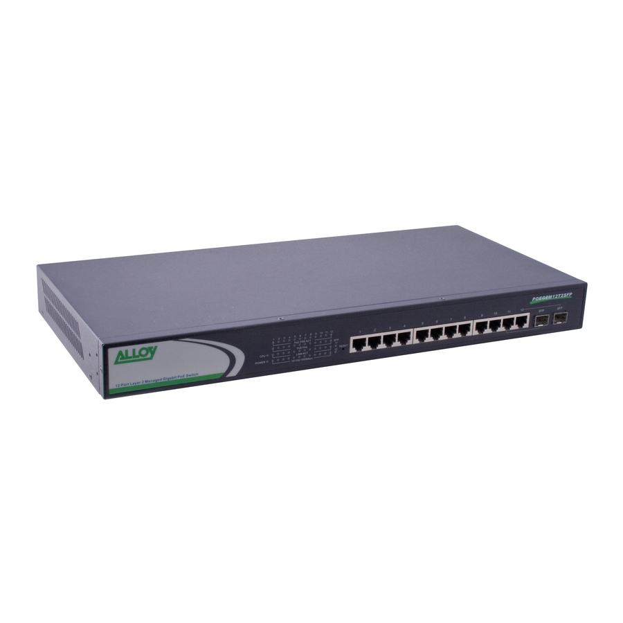
• The trap event and alarm message can be transferred via e-mail and mobile phone short message • TFTP for firmware upgrade, system log upload and config file import/export 1.4. Overview of the POEGEM12T2SFP Switch Fig. 1-1: Front View of the POEGEM12T2SFP Switch POEGEM12T2SFP User Manual Alloy Computer Products Pty Ltd Copyright ©2006... -
Page 10: User Interfaces On The Front Panel (Button, Led's And Plugs)
RJ-45 ports on the switch. There are also 2 LED’s that indicate the status of each of the SFP ports. TP and PoE Port Status Indication Power Indication LED & CPU LED Fig. 1-2 : Front View of the POEGEM12T2SFP Switch LED Indicators Colour POWER Green... -
Page 11: User Interfaces On The Rear Panel
1.5. Overview of the Optional SFP Modules With the POEGEM12T2SFP switch, the SFP ports are paired with RJ-45 copper ports 11 and 12. Only one of any given paired port can be used. In this manner, these paired ports can be seen as ‘Dual Media’... - Page 12 POEGEM12T2SFP User Manual Fig. 1-4: Front View of Fig. 1-5: Front View of 1000Base-SX/LX LC, 1000Base-LX WDM LC SFP Fibre Transceiver SFP Fibre Transceiver Alloy Computer Products Pty Ltd Copyright ©2006...
-
Page 13: Starting The Poegem12T2Sfp Snmp Managed Poe Switches
2. Installation 2.1. Starting the POEGEM12T2SFP SNMP Managed POE Switches This section provides a quick start guide for: • Hardware and Cable Installation • Management Station Installation • Software booting and configuration 2.1.1. Hardware and Cable Installation Please Note: ⇒ Wear a grounding strap to avoid damaging the switch with an electrostatic discharge ⇒... -
Page 14: Firmware Loading
• Power On Please Note: ⇒ The Alloy POEGEM12T2SFP uses a 100-240 VAC, 50-60 Hz power supply. The power supply will automatically convert your local AC power source to DC power for use by the switch. 1. Ensure that the power switch is turned off before connecting mains power. -
Page 15: Cabling Requirements
Gigabit Fibre with single-mode/single core WDM SC 1550nm SFP mini-GBIC modules The following table lists the types of fibre optic cable that are supported by SFP mini-GBIC modules installed in the POEGEM12T2SFP. Other cable types not listed here may be supported; please contact the supplier of your switch for details. -
Page 16: Management Options Available With The Poegem12T2Sfp
2.1.3.1. Configuring the POEGEM12T2SFP through the RS-232 serial port When configuring the POEGEM12T2SFP via the RS-232 console please connect the switch via the provided serial cable to a DCE device such as a PC. Once you have connection run a terminal emulation program such as Hyper Terminal. - Page 17 Enter. 4. Type save start to save the new switch configuration as the startup configuration for the switch. 5. Type logout to exit the switch’s management. POEGEM12T2SFP User Manual Fig. 2-2 Fig. 2-3 Alloy Computer Products Pty Ltd Copyright ©2006...
-
Page 18: Configuring The Poegem12T2Sfp Through The Ethernet Port
POEGEM12T2SFP User Manual 2.1.3.2. Configuring the POEGEM12T2SFP through the Ethernet Port There are three different methods of configuring the POEGEM12T2SFP through the Ethernet Port. They are CLI, Web Browser and via SNMP Management Software. We will not cover SNMP management in this manual as it will vary depending on the Network Management Software that is being used. - Page 19 You will now be prompted to log into the switch, the default username and password is shown below: Username: admin Password: admin Fig. 2.5 Note: The CLI configuration will be covered in detail in Chapter 4. Alloy Computer Products Pty Ltd Copyright ©2006...
-
Page 20: Operation Of The Web Based Management
Username: admin Password: admin Once you have entered the IP address of the POEGEM12T2SFP into a web browser you will be prompted with a login screen where you will need to enter a valid username and password to gain access to the switch. The default username and password are shown above. -
Page 21: Web Management Home Overview
Model Name, System Description, Location, Contact, Device Name, System Up Time, Current Time, BIOS Version, Firmware Version, Hardware-Mechanical Version, Serial Number, Host IP Address, Host MAC Address, Device Port, RAM Size and Flash Size. Fig. 3-2 Alloy Computer Products Pty Ltd Copyright ©2006... - Page 22 At the left hand side of the screen is the main menu tree. This menu is used to navigate your way around the switch’s web interface. The image below shows the menu tree for the web interface: Fig. 3-4 Alloy Computer Products Pty Ltd Copyright ©2006...
-
Page 23: System Information
Click the <apply> button to update. (Read/Write) Device Name: Specify a descriptive device name for the switch. Location name can be up to 36 Alphanumeric Characters long. Click the <apply> button to update. (Read/Write) POEGEM12T2SFP User Manual Fig. 3-5 Alloy Computer Products Pty Ltd Copyright ©2006... - Page 24 Specifies the port density and types of ports on the switch. (Read Only) RAM Size: The size of the DRAM in this switch. (Read Only) Flash Size: The size of the flash memory in the switch. (Read Only) Alloy Computer Products Pty Ltd Copyright ©2006 POEGEM12T2SFP User Manual...
-
Page 25: Ip Configuration
3-1-2. IP Configuration The IP configuration is used to set the IP settings in the switch. The POEGEM12T2SFP supports either a static IP address allocated via the system administrator or can be assigned an IP address dynamically from a DHCP server on your network. The IP address is used to gain access to the management functionality of the switch. - Page 26 DNS address in the switch. A DNS Server address should be given to you from your ISP. Enter the required DNS Server in the space provided. Click the <apply> button to update. Default: 0.0.0.0 Alloy Computer Products Pty Ltd Copyright ©2006 POEGEM12T2SFP User Manual...
-
Page 27: Time Configuration
3-1-3. Time Configuration The POEGEM12T2SFP provides two methods to keep the switch’s time settings correct, they are via manual input and via a Time Server on the internet. If you are manually entering your time settings enter the “Year”, “Month”, “Day, “Hour”, “Minute” and “Seconds” into the space provided. - Page 28 Click the <apply> button to update. Default: 0 Default values for starting and ending date: Start: Month = 1, Day = 1, Hour = 0 End: Month = 1, Day = 1, Hour = 0 Alloy Computer Products Pty Ltd Copyright ©2006...
-
Page 29: Account Configuration
The account configuration is used to create or modify guest and administrator accounts. The POEGEM12T2SFP allows the administrator to create up to 5 guest accounts, accounts can only be created by the administrator. When a Guest user logs into the switch they will not be able to modify any parameters, they just have read only rights to the switch. - Page 30 Please enter a username for the administrator or guest account, a maximum of 15 alphanumeric characters only. Password: Please enter a password for the administrator or guest account, a maximum of 15 alphanumeric characters only. Confirm Password: Please confirm the password. Alloy Computer Products Pty Ltd Copyright ©2006 POEGEM12T2SFP User Manual...
-
Page 31: Management Security Configuration
If you wish to lock the management down to a particular IP range please select the Custom radio button and enter the IP range in the space provided. Otherwise select the Any radio button. POEGEM12T2SFP User Manual Fig. 3-9 Alloy Computer Products Pty Ltd Copyright ©2006... - Page 32 If you have an existing rule that you want to edit select the rule from the list, make your changes and click on the edit button. Delete: Select a rule from the list and click the Delete button to remove that rule. Alloy Computer Products Pty Ltd Copyright ©2006 POEGEM12T2SFP User Manual...
-
Page 33: Virtual Stack Configuration
The Virtual Stack function allows multiple POEGEM12T2SFP switches to be managed from a single IP Address. One POEGEM12T2SFP switch will be configured as a Master and all other POEGEM12T2SFP switches will be configured as Slaves. You can then apply a group name to the virtual stack, only one master switch can exist within the same group name. -
Page 34: Port Configuration
Additional Information is also available for ports 11 and 12 when running SFP modules. Fig. 3-12 Alloy Computer Products Pty Ltd Copyright ©2006... - Page 35 If the port does not have an active link and is configured to run in auto-negotiation mode then Auto will be displayed. Flow Control: Shows the port’s flow control status. The POEGEM12T2SFP switches support both Backpressure flow control for Half Duplex and Pause flow control for Full Duplex.
- Page 36 Displays the maximum speed the SFP module supports. Vendor OUI: Displays the manufacturers OUI code which is assigned by the IEEE. Vendor Name: Displays the company name of the SFP module manufacturer. Vendor PN: POEGEM12T2SFP User Manual Fig. 3-13 Alloy Computer Products Pty Ltd Copyright ©2006...
- Page 37 Mon1(Bias) mA: Shows the Bias current of the SFP module. Mon2(TX PWR): Shows the transmit power of the SFP Module. Mon3(RX PWR): Shows the receive power of the SFP Module. Alloy Computer Products Pty Ltd Copyright ©2006 POEGEM12T2SFP User Manual...
-
Page 38: Port Configuration
Is used to set the speed and duplex settings for a particular port. If Auto is displayed the port is running in auto-negotiation mode. If you are connecting to a POEGEM12T2SFP User Manual Fig. 3-14 Alloy Computer Products Pty Ltd Copyright ©2006... - Page 39 Duplex (1G/Full). Default: Auto Flow Control: Shows the port’s flow control status. The POEGEM12T2SFP switches support both Backpressure flow control for Half Duplex and Pause flow control for Full Duplex. Select Enable to enable flow control and Disable to disable flow control.
-
Page 40: Simple Counter
Displays the total amount of packets transmitted. RX Packet: Displays the total amount of packets received. TX Collision: Displays the total amount of transmitted collisions that have occurred. POEGEM12T2SFP User Manual Fig. 3-15 Alloy Computer Products Pty Ltd Copyright ©2006... - Page 41 This is measured in seconds and ranges from 3 – 10. Default: 3 seconds. Reset: The reset button is located at the top right hand side of the screen and is used to reset the counters back to zero. Alloy Computer Products Pty Ltd Copyright ©2006 POEGEM12T2SFP User Manual...
-
Page 42: Detail Counter
Displays the total number of received packets classified as High Priority. RX Low Priority Packets: Displays the total number of received packets classified as Low Priority. RX Broadcast: Displays the total number of broadcast packets received. POEGEM12T2SFP User Manual Fig. 3-16 Alloy Computer Products Pty Ltd Copyright ©2006... - Page 43 TX 128 ~ 255 Bytes: Displays the total number of 128 ~ 255 byte frames transmitted. TX 256 ~ 511 Bytes: Displays the total number of 256 ~ 511 byte frames transmitted. Alloy Computer Products Pty Ltd Copyright ©2006 POEGEM12T2SFP User Manual...
- Page 44 3 – 10. Default: 3 seconds. Reset: The reset button is located at the top right hand side of the screen and is used to reset the counters back to zero. Alloy Computer Products Pty Ltd Copyright ©2006 POEGEM12T2SFP User Manual...
-
Page 45: Poe
- but still allow them to run on the switch as in the case of a normal Ethernet device. The POEGEM12T2SFP uses an injection voltage of about 48VDC on pins 1, 2, 3, 6 3-3-1. POE Status... - Page 46 If the total power drawn from each of the ports on the switch exceeds the switches power limit, ports will need to be disabled based on the priority given to each of the ports. Alloy Computer Products Pty Ltd Copyright ©2006 POEGEM12T2SFP User Manual...
-
Page 47: Poe Configuration
The priority order is Low, Normal and then High. If all ports have the same priority level the port with the highest port ID eg. Port number 12, will be disabled first. POEGEM12T2SFP User Manual Fig. 3-18 Alloy Computer Products Pty Ltd Copyright ©2006... - Page 48 The total power been drawn from each port. Current (mA): The total current supplied to the PD. Class: The Class of the PD connected to the port of the switch. Alloy Computer Products Pty Ltd Copyright ©2006 POEGEM12T2SFP User Manual...
-
Page 49: Mirror
3-4. Mirror The Mirror function of the POEGEM12T2SFP switches is used to capture data from a particular port on the switch. Any port on the switch can be selected as the monitoring port; this port will be used to capture data from another port on the switch using third party data capturing software. -
Page 50: Bandwidth
3-5. Bandwidth The Bandwidth Management function of the POEGEM12T2SFP switches is used to limit the bandwidth a port may use when sending or receiving data. When limiting received data you can limit the bandwidth on a particular type of data, including all Traffic or Multicast and Broadcast Traffic. - Page 51 Traffic may be lost if the egress buffers are full. The Egress Rate Limiting will limit all data including unicast, broadcast and multicast traffic. Valid range is 0 ~ 1000. Default State: Disable Alloy Computer Products Pty Ltd Copyright ©2006 POEGEM12T2SFP User Manual...
-
Page 52: Qos (Quality Of Service)
Per Port Priority Function Description: The POEGEM12T2SFP switch allows the administrator to configure High and Low priority levels to individual ports on the switch. For instance if port 1 is set to High priority and port 2 is set to Low priority and both ports are transmitting data at 1G to port 5, packets transmitted from port 2 will be dropped if there is congestion in the switch. - Page 53 VLAN Tag Priority Function Description: The POEGEM12T2SFP allows the administrator to configure priority levels based on a priority field found inside the VLAN Tag. This priority field contains 3 bits which allow a total of 8 priority levels to be configured: 000, 001, 010, 011, 100, 101, 110 and 111.
- Page 54 IP TOS Classification Function Description: The POEGEM12T2SFP allows the administrator to configure priority levels based on the TOS field of the IP Header. There are three bits in the TOS field which can be arranged into 8 different traffic classes: 000, 001, 010, 011, 100, 101, 110 and 111.
- Page 55 IP TCP/UDP Port Classification Function Description: The POEGEM12T2SFP allows the administrator to configure QoS rules based on Layer 4 networking protocols such as HTTP, FTP etc. The switch provides built in rules to down prioritise, or prioritise different types of services. If the built in rules do not suit your particular application, custom services can also be created based on a particular TCP/UDP port number.
- Page 56 20, 21, 69, 119, 2009 Prioritise IP Telephony (VoIP): 1718, 1719, 1720 Prioritise iSCSI: 3225, 3260, 3420 Prioritise web browsing, email, FTP and news: 80, 280, 443, 25, 110, 20, 21, 69, 119, 2009 Alloy Computer Products Pty Ltd Copyright ©2006 POEGEM12T2SFP User Manual...
- Page 57 Prioritise Streaming Audio/Video: 2979, 1755, 7070, 7071, 554, 8000 Prioritise Databases (Oracle, IBM DB2, SQL, Microsoft): 66, 1571, 1575, 523, 118, 156, 3306, 1232, 1433, 1434 Fig. 3-25 Advanced Mode Fig. 3-26 Simple Mode Alloy Computer Products Pty Ltd Copyright ©2006 POEGEM12T2SFP User Manual...
- Page 58 IP Diffserve Classification: Function Description: The POEGEM12T2SFP allows the administrator to configure priority levels based on the 6-bit field in the DSCP of the IP packet. The 6-bit field allows a total of 64 different traffic classes in which you can set a High or a Low priority.
-
Page 59: Snmp Configuration
SMI syntax. The SNMP agent is running on the switch to respond to requests issued by an SNMP manager. The POEGEM12T2SFP allows the administrator to turn the SNMP agent on or off. If SNMP is set to “Enable”, the SNMP agent will be started. All supported MIB OIDs, including RMON MIB, can be accessed via an SNMP manager. - Page 60 Default port number: 162 Trap: In the POEGEM12T2SFP, there are six trap hosts supported. Each of them has its own community name and IP address; which are user-definable. To configure a Trap host you will need a network management System to receive the Trap messages from the switch.
-
Page 61: Igmp Snooping
The POEGEM12T2SFP support all functions of IGMP Snooping including query, report and leave. IGMP Snooping is used by the switch to learn who belongs to a multicast group and also update the multicast table within the switch with new multicast members. - Page 62 VLAN ID: Shows the VLAN ID for each multicast group. Member Port: Shows the member ports of each multicast group, a group may contain a single host or multiple hosts. Alloy Computer Products Pty Ltd Copyright ©2006 POEGEM12T2SFP User Manual...
-
Page 63: Max. Packet Length
3-9. Max. Packet Length The POEGEM12T2SFP supports Jumbo frames up to 9k in size to allow transmission of large amounts of data in a network environment. When using Jumbo Frames you will need to ensure that all connecting devices support Jumbo frames otherwise devices that do not support this will drop the packet because of it unusual size. -
Page 64: Dhcp Boot
3-10. DHCP Boot The POEGEM12T2SFP supports DHCP Broadcast Suppression allowing the switch to suppress broadcast traffic. If a network loses power and then regains power and all computers on the network boot at the same time, a lot of broadcast traffic is generated especially if all nodes on your network are using DHCP. -
Page 65: Vlan (Virtual Local Area Network)
3-11. VLAN (Virtual Local Area Network) The POEGEM12T2SFP supports both 802.1q Tagged based VLAN’s and Port-based VLAN’s. VLAN’s are used to logically separate your network into smaller more defined networks. VLAN’s help to reduce broadcast traffic across your network as all broadcast traffic will be limited to the VLAN group in which it belongs. - Page 66 In addition this method enables customers to maintain their desired tag, without concern that other organisations will share the same ID. Service providers avoid potential problems by simply adding a second ID per customer in addition to the shared tag. Alloy Computer Products Pty Ltd Copyright ©2006 POEGEM12T2SFP User Manual...
- Page 67 Each port of the switch can no longer communicate with each other they can only communicate with the uplink ports chosen therefore creating 11 or 12 port- based VLAN groups containing three member ports in each group. Fig. 3-33 Alloy Computer Products Pty Ltd Copyright ©2006...
-
Page 68: Tag-Based Group
SYM-VLAN. You will now have to select what ports you would like to belong to this group. Click the Apply button for the POEGEM12T2SFP User Manual Fig. 3-34 Alloy Computer Products Pty Ltd Copyright ©2006... - Page 69 VLAN group from the table. Edit: Highlight the VLAN group you wish to edit and click the Edit button to modify the selected VLAN group. Alloy Computer Products Pty Ltd Copyright ©2006 POEGEM12T2SFP User Manual Fig. 3-35 Fig. 3-36...
-
Page 70: Port-Based Group
Port-based Group Configuration Function description: Shows information of the existing port-based VLAN groups, the administrator can also Add, Delete and Edit VLAN’s using the function buttons provided. POEGEM12T2SFP User Manual Fig. 3-37 Fig. 3-38 Alloy Computer Products Pty Ltd Copyright ©2006... - Page 71 Click the Apply button for the settings to take effect. Delete: Highlight the VLAN group you wish to delete and click the Delete button to remove the VLAN group from the table. POEGEM12T2SFP User Manual Fig. 3-39 Alloy Computer Products Pty Ltd Copyright ©2006...
- Page 72 Edit: Highlight the VLAN group you wish to edit and click the Edit button to modify the selected VLAN group. Alloy Computer Products Pty Ltd Copyright ©2006 POEGEM12T2SFP User Manual Fig. 3-40 Fig. 3-41...
-
Page 73: Tag Rule
VID=100, and Rule 1 is enabled, the switch will check if port 1 is a member of VLAN100. If yes, the received packet is forwarded: otherwise, the received packet is dropped. POEGEM12T2SFP User Manual Fig. 3-42 Alloy Computer Products Pty Ltd Copyright ©2006... - Page 74 VID matches the VID configured in the Untag VID section. Untag VID: Valid range is 0 – 4094. This will only work if the Role is set to Hybrid. Alloy Computer Products Pty Ltd Copyright ©2006 POEGEM12T2SFP User Manual Fig. 3-43...
-
Page 75: Mac Table
Select an entry from the MAC table; the MAC address from that entry will be displayed. Alias: Set up an Alias for the selected MAC address. Set Alias: Saves the Alias to the MAC address selected. POEGEM12T2SFP User Manual Fig. 3-44 Alloy Computer Products Pty Ltd Copyright ©2006... - Page 76 The port in which the MAC addresses were found. VID: VLAN group in which the searched MAC address exists. State: Displays the method used to discover the MAC address, this can either be Static or Dynamic. POEGEM12T2SFP User Manual Alloy Computer Products Pty Ltd Copyright ©2006...
-
Page 77: Mac Table Maintenance
– 65535 seconds. This time-out value does not apply to Static MAC entries. Default: 300 seconds Flush: Removes all MAC entries form the Mac table except for Static MAC entries. POEGEM12T2SFP User Manual Fig. 3-45 Alloy Computer Products Pty Ltd Copyright ©2006... -
Page 78: Static Forward
VLAN Identifier, this will only be used if tagged VLAN’s are applied. Valid range is 1 – 4094. Alias: Alias name of the MAC address that has been assigned. POEGEM12T2SFP User Manual Fig. 3-46 Alloy Computer Products Pty Ltd Copyright ©2006... -
Page 79: Static Filter
VLAN Identifier, this will only be used if tagged VLAN’s are applied. Valid range is 1 – 4094. Alias: Alias name of the MAC address that has been assigned. POEGEM12T2SFP User Manual Fig. 3-47 Alloy Computer Products Pty Ltd Copyright ©2006... -
Page 80: Mac Alias
Delete button. Parameters description: MAC: Enter the MAC address you wish to assign a user friendly name to. Alias: Enter a user friendly name for the MAC address. POEGEM12T2SFP User Manual Fig. 3-48 Alloy Computer Products Pty Ltd Copyright ©2006... -
Page 81: Gvrp
Parameters description: GVRP State Setting: Used to enable or disable the GVRP function. Select your option from the drop down box and click the Apply button. Default: Disable POEGEM12T2SFP User Manual Fig. 3-49 Alloy Computer Products Pty Ltd Copyright ©2006... - Page 82 Disabled: The dynamic VLAN will be created when this port receives a GVRP BDU. This is the default setting. Alloy Computer Products Pty Ltd Copyright ©2006 POEGEM12T2SFP User Manual of a Second, Valid time range is 20 of a Second, Valid time range is...
-
Page 83: Gvrp Counter
The total number of GARP BPDU with Leave All Messages received by the GARP application. Join Empty Message Packets: The total number of GARP BPDU with Join Empty Messages received by the GARP application. POEGEM12T2SFP User Manual Fig. 3-50 Alloy Computer Products Pty Ltd Copyright ©2006... - Page 84 Leave Empty Message Packets: The total number of GARP BPDU with Leave Empty Messages transmitted by the GARP application. Empty Message Packets: The total number of GARP BPDU with Empty Messages transmitted by the GARP application. Alloy Computer Products Pty Ltd Copyright ©2006...
-
Page 85: Gvrp Group Information
When you have created a GVRP group, you can use the Administrative control function to change the Applicant and Registrar modes of the GVRP group. Refresh: Click the refresh button to get current GVRP group status. POEGEM12T2SFP User Manual Fig. 3-51 Alloy Computer Products Pty Ltd Copyright ©2006... -
Page 86: Stp
Default: 32768 Designated Root: Shows the root bridge ID for this network segment. If this switch is the root bridge, the “Designated Root” will be this switches bridge ID. POEGEM12T2SFP User Manual Fig. 3-52 Alloy Computer Products Pty Ltd Copyright ©2006... - Page 87 Shows the accumulated time in units of seconds since the last STP Topology Change was made. When a Topology Change is initiated again, this counter will be reset to 0. Alloy Computer Products Pty Ltd Copyright ©2006 POEGEM12T2SFP User Manual...
-
Page 88: Stp Configuration
I am alive. When the POEGEM12T2SFP is the root bridge of the network, for example all other bridges will use the hello time assigned by this switch to communicate with each other. - Page 89 Max. Age: If the POEGEM12T2SFP is the root bridge, the whole network will apply this figure as their maximum age time. When a switch receives a BPDU message originating from the root bridge and if the message age exceeds the maximum age of the bridge, the bridge will treat the root bridge as malfunctioned and issue a Topology Change Notification (TCN) BPDU to all other bridges.
-
Page 90: Stp Port Configuration
Path Cost Status: Determines the shortest path to the root bridge, the smaller the path cost value the more possible the port will become the root port. POEGEM12T2SFP User Manual Fig. 3-54 Alloy Computer Products Pty Ltd Copyright ©2006... - Page 91 STP BPDU at the next transmission. The only benefit of this operation is to make the port quickly act as an RSTP port. Click the <M Check> button to send a RSTP BPDU from the port you specified. Alloy Computer Products Pty Ltd Copyright ©2006 POEGEM12T2SFP User Manual...
-
Page 92: Trunking Configuration
Using Static trunking at both ends of the link is highly recommended. The POEGEM12T2SFP allow up to 8 LACP trunk groups and another additional 8 trunk groups for static trunking. Only 8 groups can be used at one time. Each trunk group can contain a maximum of 12 member ports. -
Page 93: Trunk Port Settings/Status
This field will only be used when using LACP. Active: An Active LACP port will send LACPDU to its link partner right after the LACP protocol entity has started to take control of the port. POEGEM12T2SFP User Manual Fig. 3-55 Alloy Computer Products Pty Ltd Copyright ©2006... - Page 94 This aggregator port is usually the port with the smallest port number within the trunking group. Status: This field represents the status of a port belonging to a trunking group. Alloy Computer Products Pty Ltd Copyright ©2006 POEGEM12T2SFP User Manual...
-
Page 95: Aggregator View
Shows the method the port uses to aggregate with other ports. Member Ports: Shows all member ports of an aggregator. Ready Ports: Shows only the ready member ports within an aggregator. POEGEM12T2SFP User Manual Fig. 3-56 Alloy Computer Products Pty Ltd Copyright ©2006... -
Page 96: Lacp Detail
Shows the key value of the aggregator. The key value is determined by the LACP protocol entity and can’t be set through the management. Trunk Status: Shows the trunk status of a single port. POEGEM12T2SFP User Manual Fig. 3-57 Alloy Computer Products Pty Ltd Copyright ©2006... -
Page 97: Lacp System Priority
ID is a 64-bit field comprising of a 48-bit MAC address and a 16-bit priority value. The system priority can be set by the administrator with a valid range from 1 to 65535. Default: 32768 POEGEM12T2SFP User Manual Fig. 3-58 Alloy Computer Products Pty Ltd Copyright ©2006... -
Page 98: Configuration
A device that provides the authentication service, through EAP, to an authenticator by using authentication credentials supplied by the supplicant to determine if the supplicant is authorised to access the network resource. POEGEM12T2SFP User Manual Alloy Computer Products Pty Ltd Copyright ©2006... - Page 99 Supplicant’s Authenticator’s System System Services Offered by Authenticator Supplicant (e.g Bridge Relay) Controlled port POEGEM12T2SFP User Manual Authenticator Uncontrolled port Port Authorize MAC Enable Fig. 3-59 Alloy Computer Products Pty Ltd Copyright ©2006 Authentication Server’s System Authentication Server...
- Page 100 Authentication server Authenticator Fig. 3-60 Only MultiHost 802.1X authentication is supported in the POEGEM12T2SFP. In this mode devices connected to an 802.1x enabled port, can access network resources once the supplicant has been authenticated. Alloy Computer Products Pty Ltd Copyright ©2006...
-
Page 101: State
The secret key is used to authenticate the RADIUS server with the Authenticator. The secret key is an ASCII based string with a length of 1 – 31 characters, with no blank spaces allowed. Default: Radius POEGEM12T2SFP User Manual Fig. 3-61 Alloy Computer Products Pty Ltd Copyright ©2006... -
Page 102: Mode
There are two modes that can be selected, they are Disabled and Multihost mode. Disable: The selected port will not use 802.1x authentication. Multihost: Once the supplicant has been authenticated they can then access network resources through that port. POEGEM12T2SFP User Manual Fig. 3-62 Alloy Computer Products Pty Ltd Copyright ©2006... -
Page 103: Security
If the port has been authorised, authorised will be displayed in the ports status section, if the user has not been authorised, then unauthorised will be displayed. POEGEM12T2SFP User Manual Fig. 3-63 Alloy Computer Products Pty Ltd Copyright ©2006... -
Page 104: Parameter Setting
Default: Auto reAuthMAx (1-10): The number of authentication attempts that are permitted before the port becomes unauthorised. Default: 2 txPeriod (1 – 65535 sec.): POEGEM12T2SFP User Manual Fig. 3-64 Alloy Computer Products Pty Ltd Copyright ©2006... - Page 105 Valid range: 1 – 65535. Default: 30 serverTimeout (1- 65535 sec.): A time out condition in the exchange between the authenticator and the authentication server. Valid range: 1 – 65535. Default: 30 Alloy Computer Products Pty Ltd Copyright ©2006 POEGEM12T2SFP User Manual...
-
Page 106: Alarm Configuration
3-17. Alarm Configuration The POEGEM12T2SFP supports a number of trap messages that can be sent to an administrator if certain events occur on the switch. The switch offers 24 different trap events that can be sent to the administrator in 3 different ways; email, mobile phone SMS or trap. - Page 107 Tick the required trap method check box to enable a trap to be sent when a LACP Port has failed. GVRP Disabled: Tick the required trap method check box to enable a trap to be sent when GVRP has been disabled. GVRP Enabled: Alloy Computer Products Pty Ltd Copyright ©2006 POEGEM12T2SFP User Manual...
- Page 108 Dual Media Swapped: Tick the required trap method check box to enable a trap to be sent when the dual media port has been swapped from fibre to copper or vice versa. Alloy Computer Products Pty Ltd Copyright ©2006 POEGEM12T2SFP User Manual...
-
Page 109: Email/Sms Configuration
The Alarm Configuration is used to configure who should receive the trap messages via Email, SMS or both which have been sent from the POEGEM12T2SFP. Up to 6 email addresses can be entered as well as 6 SMS mobile phone numbers. If using SMS you will need to enter the SMS ISP details. - Page 110 Password: Enter the password required by the SMS server. Email Address 1 – 6: Enter the mobile phone number(s) that will receive the trap messages. Alloy Computer Products Pty Ltd Copyright ©2006 POEGEM12T2SFP User Manual...
-
Page 111: Configuration
3-18. Configuration The POEGEM12T2SFP supports multiple configuration files to be used by the administrator including the default configuration, start configuration and user configuration. In this section the administrator can save the switch’s configuration, restore the switch to factory default and also save the current configuration as the startup configuration when the switch is re-booted. -
Page 112: Config File
Enter the file path of where you would like to import the configuration file from. Import Start: After configuring the import path click on the import start button to import the startup configuration file. POEGEM12T2SFP User Manual Fig. 3-68 Alloy Computer Products Pty Ltd Copyright ©2006... -
Page 113: Diagnostics
Import User-Conf: After configuring the import path click on the import user-conf button to import the User-Conf configuration file. 3-19. Diagnostics Three Diagnostic tools are supported in the POEGEM12T2SFP including Diagnostics, Loopback test and Ping test. 3-19-1. Diag Function name:... -
Page 114: Loopback Test
Loopback Test Function description: The POEGEM12T2SFP supports two types of loopback tests including an Internal and an External loopback test. The internal loopback test is an internal test and no test signal is sent out of the switch. The external loopback test will send the test signal to its link partner to check if the port has got an active link. -
Page 115: Ping Test
3-19-3. Ping Test Function name: Ping Test Function description: The POEGEM12T2SFP supports a ping test function to allow the switch to test communication between other IP based devices. Parameters description: IP Address: Enter an IP Address that you would like to test connectivity between. -
Page 116: Tftp Server
3-20. TFTP Server Function name: TFTP Server Function description: Used to set the IP address of the TFTP Server. Parameters description: Server: Enter the IP address of the TFTP Server. POEGEM12T2SFP User Manual Fig. 3-72 Alloy Computer Products Pty Ltd Copyright ©2006... -
Page 117: Log
Function description: The Trap Log Data displays all SNMP Private trap events, SNMP Public traps and all other user logs. The POEGEM12T2SFP supports up to 120 log entries. Parameters description: Displays the order number of all entries in the log. -
Page 118: Firmware Upgrade
3-22. Firmware Upgrade The POEGEM12T2SFP allows the administrator to upgrade the firmware to improve the features and capabilities of the switch. The firmware is upgraded via a TFTP server using any Ethernet port on the switch. Function name: Firmware Upgrade Function description: Used to upload new firmware into the POEGEM12T2SFP. -
Page 119: Reboot
3-23. Reboot The POEGEM12T2SFP allows the Administrator to reboot the switch from the web management you can also reboot the switch using the reset button on the front panel of the switch. Function name: Reboot Function description: Used to reboot the switch, this can also be performed via the RESET button on the front panel of the switch. -
Page 120: Logout
Click the Logout button to log out of the management interface. Auto Logout: The Web management interface allows the user to be automatically logged out after a predetermined period of the time. Default: 3 minutes POEGEM12T2SFP User Manual Fig. 3-76 Alloy Computer Products Pty Ltd Copyright ©2006... -
Page 121: Operation Of Cli Management
4-1. CLI Management Refer to chapter 2 for basic installation. When configuring the POEGEM12T2SFP via the RS-232 console please connect the switch via the provided serial cable to a DCE device such as a PC. Once you have connection run a terminal emulation program such as Hyper Terminal. -
Page 122: Commands Of The Cli
4-2. Commands of the CLI To display the list of commands that are supported on the POEGEM12T2SFP CLI type “?” and press enter. All commands on the switch are divided into 2 groups Global commands and Local commands. The Global commands include “exit”, “end”, “help”, “history”, “logout”, “save start”, “save user”, “restore default”... - Page 123 POEGEM12T2SFP User Manual Fig. 4-3 Alloy Computer Products Pty Ltd Copyright ©2006...
-
Page 124: Global Commands Of The Cli
Use this command to return to the root menu. Unlike the exit command which will take you back to the previous menu, the end command will take you directly to the root menu. Argument: None. Possible value: None. Example: POEGEM12T2SFP# alarm POEGEM12T2SFP(alarm)# events POEGEM12T2SFP(alarm-events)# end POEGEM12T2SFP# Alloy Computer Products Pty Ltd Copyright ©2006... - Page 125 Show a list of previously run commands logout Logout of the system save start Save as start config save user Save as user config restore default Restore default config restore user Restore user config POEGEM12T2SFP(ip)# POEGEM12T2SFP User Manual Alloy Computer Products Pty Ltd Copyright ©2006...
- Page 126 6. trunk 7. exit 8. alarm 9. events 10. end 11. ip 12. help 13. ip 14. history POEGEM12T2SFP(ip)# history 3 Command history: 13. ip 14. history 15. history 3 POEGEM12T2SFP User Manual Alloy Computer Products Pty Ltd Copyright ©2006...
- Page 127 When you enter this command, the CLI will save your current configuration into the non-volatile FLASH as the start up configuration. Argument: None. Possible value: None. Example: POEGEM12T2SFP# save start Saving start... Save Successfully POEGEM12T2SFP# Alloy Computer Products Pty Ltd Copyright ©2006...
- Page 128 If you select “N” or “n” you will return to the previous screen. Argument: None. Possible value: None. Example: POEGEM12T2SFP# restore default Restoring ... Restore Default Configuration Successfully Press any key to reboot system. Alloy Computer Products Pty Ltd Copyright ©2006...
- Page 129 If you select “N” or “n” you will return to the previous screen. Argument: None Possible value: None Example: POEGEM12T2SFP# restore user Restoring ... Restore User Configuration Successfully Press any key to reboot system. Alloy Computer Products Pty Ltd Copyright ©2006...
-
Page 130: Local Commands Of Cli
: Fri Apr 15 01:26:11 2005 : v1.01 : v2.12 : v1.01-v1.01 : 123456789012 : 192.168.1.1 : 00-00-8C-02-10-54 : UART * 1, TP * 12, Dual-Media Port(RJ45/SFP) * 2 : 16 M : 2 M Alloy Computer Products Pty Ltd Copyright ©2006... - Page 131 POEGEM12T2SFP User Manual Syntax: set location <location string> Description: Enter a descriptive location for the POEGEM12T2SFP. Argument: String length up to 32 characters. Possible values: a, b, c, d, ... ,z and 1, 2, 3, …. etc. Example: POEGEM12T2SFP(system)# set location Canberra...
- Page 132 To set the IP address of a DNS server. Argument: <ip address> : dns ip address Possible value: 168.95.1.1 Example: POEGEM12T2SFP(ip)# set dns 168.95.1.1 : Sets the POEGEM12T2SFP DNS Server address to 168.95.1.1 Alloy Computer Products Pty Ltd Copyright ©2006...
- Page 133 : Enables DHCP function and sets DNS server via manual mode. disable dhcp Syntax: disable dhcp Description: Disables the DHCP function in the Switch. Argument: None Possible value: None Example: POEGEM12T2SFP(ip)# disable dhcp : Disables the DHCP function. Alloy Computer Products Pty Ltd Copyright ©2006...
- Page 134 None Example: POEGEM12T2SFP(ip)# show DHCP : Disable IP Address : 192.168.2.65 Subnet mask : 255.255.255.0 Gateway : 192.168.2.252 DNS Setting : Manual DNS Server : 168.95.1.1 Current IP : 192.168.2.65 POEGEM12T2SFP User Manual Alloy Computer Products Pty Ltd Copyright ©2006...
- Page 135 Used to set up the current time via a NTP server. Argument: : ntp server ip address or domain name timezone : time zone (GMT), range: -12 to +13 Possible value: Timezone: -12,-11…,0,1…,13 Example: POEGEM12T2SFP(time)# set ntp 210.59.157.10 8 POEGEM12T2SFP User Manual Alloy Computer Products Pty Ltd Copyright ©2006...
- Page 136 : daylight saving start month/day/hour : daylight saving end month/day/hour : Month (01-12) : Day (01-31) : Hour (00-23) Example: POEGEM12T2SFP(time)# set daylightsaving 3 10/12/01 11/12/01 Save Successfully show Syntax: show Description: To show the time configuration, including “Current Time”, “NTP Server”,” Timezone”, ”...
- Page 137 POEGEM12T2SFP User Manual Day light Saving End : Mth: 1 Day: 1 Hour: 0 Alloy Computer Products Pty Ltd Copyright ©2006...
- Page 138 POEGEM12T2SFP(account)# add Freddy Password: Confirm Password: Save Successfully Syntax: del <name> Description: Used to delete an existing account. Argument: <name> : existing user account Possible value: None. Example: POEGEM12T2SFP(account)# del Freddy Account Freddy deleted Alloy Computer Products Pty Ltd Copyright ©2006...
- Page 139 Syntax: show Description: Displays the current users configured in the switch. Argument: None. Possible value: None. Example: POEGEM12T2SFP(account)# show Account Name Identity --------------- -------- admin : Administrator guest : guest POEGEM12T2SFP User Manual Alloy Computer Products Pty Ltd Copyright ©2006...
- Page 140 : Sets port 5 to auto negotiation mode. show status Syntax: show status Description: Used to display the port’s current status. Argument: None Possible value: None Example: POEGEM12T2SFP(port)# show status POEGEM12T2SFP User Manual Alloy Computer Products Pty Ltd Copyright ©2006...
- Page 141 Used to display a detailed traffic counter for each port. Argument: <range>:syntax 1,5-7, available from 1 to 12. Possible value: 1 to 12 Example: POEGEM12T2SFP(port)# show detail-counter 5 : Displays the detailed counter for port 5 Alloy Computer Products Pty Ltd Copyright ©2006...
- Page 142 <port> Description: Used to display the SFP module information. Argument: <port>: available 11, 12 Possible value: 11, 12Example: POEGEM12T2SFP(port)# show sfp 11 : Displays the SFP module information for port 11. Alloy Computer Products Pty Ltd Copyright ©2006...
- Page 143 Description: Used to enable the port. Argument: range syntax: 1,5-7, available from 1 to 12 Possible value: <range>: 1 ~ 12 Example: POEGEM12T2SFP(port)# enable state 3-12 : Enables ports 3 through to 12. Alloy Computer Products Pty Ltd Copyright ©2006...
- Page 144 <range> Description: Used to Disable the port. Argument: range syntax: 1,5-7, available from 1 to 12 Possible value: <range>: 1 ~ 12 Example: POEGEM12T2SFP(port)# disable state 12 : Disables port 12. Alloy Computer Products Pty Ltd Copyright ©2006...
- Page 145 Used to disable flow control on a particular port. Argument: range syntax: 1,5-7, available from 1 to 12 Possible value: <range>: 1 ~ 12 Example: POEGEM12T2SFP(port)# disable flow-control 6 : Disables flow control for port 6. Alloy Computer Products Pty Ltd Copyright ©2006...
- Page 146 <#>: the monitoring port that is chosen for the mirror function. Only one port can be the monitoring port. Possible value: None Example: POEGEM12T2SFP(mirror)# set monitoring-port 2 : Enables port 2 to become the monitoring port which will capture all packets received by the monitored port. POEGEM12T2SFP User Manual Alloy Computer Products Pty Ltd Copyright ©2006...
- Page 147 Show Description: Displays the status of the mirror function. Argument: None Possible value: None Example: POEGEM12T2SFP(mirror)# show Mirror Mode : rx Monitoring Port : 2 Monitored Port : 3 4 5 7 10 Alloy Computer Products Pty Ltd Copyright ©2006...
- Page 148 <range>:syntax 1,5-7, available from 1 to 12 <data_rate>: 0-1000Mbps. Possible value: <range>: 1 to 12 <data_rate>: 0-1000Mbps. Example: POEGEM12T2SFP(bandwidth)# enable storm-rate 1-12 150 : Enables the broadcast storm rate on ports 1 through to 12 at 150. Alloy Computer Products Pty Ltd Copyright ©2006...
- Page 149 Argument: <range>:syntax 1,5-7, available from 1 to 12 Possible value: <range>: 1 to 12 Example: POEGEM12T2SFP(bandwidth)# disable ingress-rate 1-12 : Disables the Ingress rate control for all ports from 1 through to 12. Alloy Computer Products Pty Ltd Copyright ©2006...
- Page 150 Used to disable the egress-rate of the port. Argument: <range>:syntax 1,5-7, available from 1 to 12 Possible value: <range>: 1 to 12 Example: POEGEM12T2SFP(bandwidth)# disable egress-rate 1-12 Disable the egress rate control on all port from 1 through to 12. Alloy Computer Products Pty Ltd Copyright ©2006...
- Page 151 Disabled Disabled Disabled Disabled Disabled Disabled Disabled Disabled Disabled Disabled Disabled Disabled Disabled Disabled Disabled Disabled Disabled Disabled POEGEM12T2SFP User Manual Disabled Disabled Disabled Disabled Disabled Disabled Disabled Disabled Disabled Disabled Disabled Disabled Alloy Computer Products Pty Ltd Copyright ©2006...
- Page 152 Argument: class: class of service Possible value: setting. 1: high, 0: low Example: POEGEM12T2SFP(qos)# set default 1 : Sets a high priority to all ports not using the QoS function. POEGEM12T2SFP User Manual Alloy Computer Products Pty Ltd Copyright ©2006...
- Page 153 <class>: class of service setting. 1: high, 0: low Example: POEGEM12T2SFP(qos)# set pri-tag 1-10 1-2 1 : Sets a high priority level to all packets containing a VLAN tag of 1 or 2 to all ports from 1 through to 10.
- Page 154 <tos-range>: syntax: 1,5-7, available from 0 to 7 <class>: 1: high, 0: low Example: POEGEM12T2SFP(qos)# set tos 1-5 0-3 0 : Sets a low priority to all packets containing a TOS filed ranging from 0 through to 3 for all ports from 1 through to 5.
- Page 155 5: prioritise streaming Audio/Video 6: prioritise databases (Oracle, IBM DB2, SQL, Microsoft) Example: POEGEM12T2SFP(qos)# set simple-layer4 2 : Allows all IP Telephony (VoIP) traffic to be prioritized over all other traffic. POEGEM12T2SFP User Manual Alloy Computer Products Pty Ltd Copyright ©2006...
- Page 156 (all other TCP/UDP ports). 1: high, 0: low Example: POEGEM12T2SFP(qos)# set advance-layer4 5 2 80 1 0 : Prioritises port 80 (Web) traffic over all other traffic through port 5. Alloy Computer Products Pty Ltd Copyright ©2006...
- Page 157 <ds-range>: syntax: 1,5-7, available from 0 to 63 <class>: 1: high, 0: low Example: POEGEM12T2SFP(qos)# set diffserv 0-20 1 :Sets all classes of traffic with a diffserv value from 1 through to 20 with a high priority. Alloy Computer Products Pty Ltd Copyright ©2006...
- Page 158 POEGEM12T2SFP User Manual high high high high high high high high high high high high high high high high high high high high high high high high high high high high high high high high Alloy Computer Products Pty Ltd Copyright ©2006...
- Page 159 Used to disable the SNMP function. Argument: None. Possible value: None. Example: POEGEM12T2SFP(snmp)# disable snmp : Disables the SNMP function in the switch. POEGEM12T2SFP(snmp)# disable set-ability : Disables the private community of the SNMP function. Alloy Computer Products Pty Ltd Copyright ©2006...
- Page 160 POEGEM12T2SFP(snmp)# set set-community private : Sets the set-community name to private. POEGEM12T2SFP(snmp)# set trap 1 192.168.1.1 162 public : Sets trap 1 host IP address of 192.168.1.1 using port number 162. The community name is set to public. Any SNMP traps will be sent to the IP address specified above.
- Page 161 Trap Host 3 IP Address: 0.0.0.0 Port: 162 Community: public Trap Host 4 IP Address: 0.0.0.0 Port: 162 Community: public Trap Host 5 IP Address: 0.0.0.0 Port: 162 Community: public Trap Host 6 IP Address: 0.0.0.0 Port: 162 Community: public Alloy Computer Products Pty Ltd Copyright ©2006...
- Page 162 <length >(bytes): Maximum Packet Length supported Possible value: <range> : syntax 1,5-7, available from 1 to 12 <length>(bytes): 1518/1532/9216 Example: POEGEM12T2SFP(max-pkt-len)# set len 1-8 9216 : Sets packet length of 9216 bytes for ports through 1 to 8. Alloy Computer Products Pty Ltd Copyright ©2006...
- Page 163 Displays the current Maximum Packet Length of each port. Argument: None Possible value: None Example: POEGEM12T2SFP(max-pkt-len)# show PORT Max Packet Length ------ ------------------- 1518 1518 1518 1518 1518 1518 1518 1518 1518 1518 1518 1518 POEGEM12T2SFP User Manual Alloy Computer Products Pty Ltd Copyright ©2006...
- Page 164 Display’s the IGMP snooping mode and IP Multicast Table. Argument: None Possible value: None Example: POEGEM12T2SFP(igmp)# show Snoop Mode: Active IP Multicast: 1) IP Address : 224.1.1.1 VLAN ID Member Port : 22 POEGEM12T2SFP User Manual Alloy Computer Products Pty Ltd Copyright ©2006...
- Page 165 : Sets the DHCP Broadcast Suppression delay time to 30 seconds. show Syntax: show Description: Display’s the status of DHCP Broadcast Suppression. Argument: None Possible value: None Example: POEGEM12T2SFP(dhcp-boot)# show Dhcp Boot : Enable Second : 10 Alloy Computer Products Pty Ltd Copyright ©2006...
- Page 166 <disable | port | tag | metro | double-tag>: disable, port, tag, metro, double-tag [up-link]: 11 or 12 or “11,12” Example: POEGEM12T2SFP(vlan)# set mode metro 11-12 : Sets the VLAN mode for the switch to metro mode Alloy Computer Products Pty Ltd Copyright ©2006...
- Page 167 # :0,1 Example: POEGEM12T2SFP(vlan)# set tag-group 2 VLAN-2 2-5, 6 0 : Creates a Tag-based VLAN group with a VID of 2, and a group name of VLAN-2. The ports that will belong to this group are 2 to 5 and 6, sym vlan set to symmetric.
- Page 168 12. Possible value: [up-link]: 11 or 12 or “11,12” or “11-12” Example: POEGEM12T2SFP(vlan)# set mode metro 11-12 : Creates a metro mode based VLAN with ports 11 and 12 being the uplink ports. Alloy Computer Products Pty Ltd Copyright ©2006...
- Page 169 1 to 4094 Example: POEGEM12T2SFP(vlan)# set port-role 5 hybrid 6 : Sets port 5 as Hybrid mode with a VID of 6. If any packets have VID of 6 the tag will be stripped. Alloy Computer Products Pty Ltd Copyright ©2006...
- Page 170 : which port(s) you want to configure. Possible value: range: available from 1 to 12 Example: POEGEM12T2SFP(vlan)# disable sym-vlan 5-10 : Disables sym-vlan on all ports ranging from 5 through to 10. Alloy Computer Products Pty Ltd Copyright ©2006...
- Page 171 Possible value: range: available from 1 to 12 Example: POEGEM12T2SFP(vlan)# disable drop-untag 5-10 : Creates a rule so that all untagged frames received on ports 5 through to 10 will not be dropped. Alloy Computer Products Pty Ltd Copyright ©2006...
- Page 172 Description: Used to delete the port-based vlan group. Argument: name: which vlan group you want to delete. Possible value: name: port-vlan name Example: POEGEM12T2SFP(vlan)# del port-group VLAN-2 : Deletes port-based VLAN group VLAN-2 Alloy Computer Products Pty Ltd Copyright ©2006...
- Page 173 : 1 2 3 4 5 6 7 8 9 10 11 12 2) Vlan Name : VLAN-2 Vlan ID : 2 Sym-vlan : Disable Member : 2 3 4 5 6 POEGEM12T2SFP User Manual Alloy Computer Products Pty Ltd Copyright ©2006...
- Page 174 Disable Access 5 Enable Disable Access 5 Enable Disable Access 1 Enable Disable Access 1 Enable Disable Access 1 Disable Disable Access 1 Disable Disable Access POEGEM12T2SFP User Manual Port Rule Untag Vid Alloy Computer Products Pty Ltd Copyright ©2006...
- Page 175 Syntax: Show Description: Used to display all MAC table information. Argument: None Possible value: None Example: POEGEM12T2SFP(mac-table-information)# show MAC Table List Alias MAC Address Port VID State ---------------- ----------------- ---- ---- ----------------- Alloy Computer Products Pty Ltd Copyright ©2006...
- Page 176 POEGEM12T2SFP(mac-table-information)# search 1-12 ??-??-??-??-??-?? ? MAC Table List Alias MAC Address Port VID State ---------------- ----------------- ---- ---- ----------------- 00-40-c7-88-00-06 1 0 Dynamic : Searches ports 1 through to 16 for any MAC address with an VID. Alloy Computer Products Pty Ltd Copyright ©2006...
- Page 177 Description: Used to delete all of the MAC's that have been learnt dynamically. Argument: None Possible value: None Example: POEGEM12T2SFP(mac-table-maintain)# set flush : Flushes all learnt dynamic MAC addresses from the MAC table. Alloy Computer Products Pty Ltd Copyright ©2006...
- Page 178 Possible value: None Example: POEGEM12T2SFP(mac-table-static-mac)# add 00-02-03-04-05-06 3 0 Test : Adds a static MAC entry with MAC address 00-02-03-04-05-06 fro port 3 with a VID of 0 and a Alias name of Test. Alloy Computer Products Pty Ltd Copyright ©2006...
- Page 179 Description: Used to display the static forward table. Argument: None Possible value: None Example: POEGEM12T2SFP(mac-table-static-mac)# show forward Static Forwarding Entry: (Total 1 item(s)) 1) MAC: 00-02-03-04-05-06, port: 3, vid: -, alias: aaa Alloy Computer Products Pty Ltd Copyright ©2006...
- Page 180 <mac> : mac address, format: 00-02-03-04-05-06 <alias> : mac alias name, max 15 characters Possible value: None Example: POEGEM12T2SFP(mac-table-alias)# set 00-44-33-44-55-44 Test : Create a MAC Alias of Test for MAC address 00-02-03-04-05-06 Alloy Computer Products Pty Ltd Copyright ©2006...
- Page 181 Used to display the MAC alias entries. Argument: None Possible value: None Example: POEGEM12T2SFP(mac-table-alias)# show MAC Alias List MAC Address Alias ----- ----------------- ---------------- 00-02-03-04-05-06 Test 00-33-03-04-05-06 Test1 00-44-33-44-55-66 Test2 POEGEM12T2SFP User Manual Alloy Computer Products Pty Ltd Copyright ©2006...
- Page 182 Example: POEGEM12T2SFP(gvrp)# enable : Enables GVRP on the switch. disable Syntax: disable Description: Used to disable the GVRP function. Argument: None Possible value: None Example: POEGEM12T2SFP(gvrp)# disable : Disables GVRP on the switch. Alloy Computer Products Pty Ltd Copyright ©2006...
- Page 183 Leave Time must equal at least double the Join Time. Example: POEGEM12T2SFP(gvrp)# set timer 2-8 25 80 2000 : Sets the GVRP timer for ports 2 through to 8 with a join time of 25, a leave time of 80 and a leave all time of 2000.
- Page 184 <range>: syntax 1,5-7, available from 1 to 12 <normal | fixed | forbidden>: normal, fixed or forbidden Example: POEGEM12T2SFP(gvrp)# set registrar 1-5 fixed : Sets ports 1 through to 5 as fixed mode. Alloy Computer Products Pty Ltd Copyright ©2006...
- Page 185 GVRP Counter port: 2 Counter Name Received Transmitted -------------------- -------- ----------- Total GVRP Packets Invalid GVRP Packets 0 ---- LeaveAll message JoinEmpty message JoinIn message LeaveEmpty message 0 Empty message POEGEM12T2SFP User Manual Alloy Computer Products Pty Ltd Copyright ©2006...
- Page 186 Normal 1000 Normal POEGEM12T2SFP User Manual Applicant Registrar Restricted Normal Disable Normal Disable Normal Disable Normal Disable Normal Disable Normal Disable Normal Disable Normal Disable Normal Disable Normal Disable Normal Disable Normal Disable Alloy Computer Products Pty Ltd Copyright ©2006...
- Page 187 POEGEM12T2SFP User Manual show group Syntax: show group Description: Used to show the GVRP group(s). Argument: none Possible value: none Example: POEGEM12T2SFP(gvrp)# show group GVRP group information VID Member Port ---- ------------------------------------------------- Alloy Computer Products Pty Ltd Copyright ©2006...
- Page 188 Description: Used to enable the STP function. Argument: None Possible value: None Example: POEGEM12T2SFP(stp)# enable disable Syntax: disable Description: Used to disable the STP function. Argument: None Possible value: None Example: POEGEM12T2SFP(stp)# disable Alloy Computer Products Pty Ltd Copyright ©2006...
- Page 189 <Max. Age>: 6 to 40. <Forward Delay>: 4 to 30. Example: POEGEM12T2SFP(stp)# set config 61440 2 20 15 : Configures the STP parameters as follows, Bridge Priority of 61440, Hello Time of 2, Max Age of 20 and a Forward Delay of 15.
- Page 190 <admin p2p>: auto / true / false Example: POEGEM12T2SFP(stp)# set port 1-12 0 128 yes auto : Configures ports 1 through to 12 with a path cost of 0, priority of 128, edge port is set as yes and the admin P2P is set to auto.
- Page 191 Designated Priority: Root Port: Root Path Cost: Current Max. Age(sec): Current Forward Delay(sec): Hello Time(sec): STP Topology Change Count: Time Since Last Topology Change(sec) : 848 POEGEM12T2SFP User Manual Enabled 00:00:8C:D8:09:1D 61440 00:00:8C:D8:09:1D 61440 Alloy Computer Products Pty Ltd Copyright ©2006...
- Page 192 Example: POEGEM12T2SFP(stp)# show config STP State Configuration: Spanning Tree Protocol: Bridge Priority (0-61440): Hello Time (1-10 sec): Max. Age (6-40 sec): Forward Delay (4-30 sec): Force Version: POEGEM12T2SFP User Manual Enabled 61440 RSTP Alloy Computer Products Pty Ltd Copyright ©2006...
- Page 193 7 DISCARDING 2000000 8 DISCARDING 2000000 9 DISCARDING 2000000 10 DISCARDING 2000000 11 DISCARDING 2000000 12 DISCARDING 2000000 POEGEM12T2SFP User Manual Auto Auto Auto Auto Auto Auto Auto Auto Auto Auto Auto Auto Alloy Computer Products Pty Ltd Copyright ©2006...
- Page 194 : set the LACP to passive mode Possible value: None Example: POEGEM12T2SFP(trunk)# set trunk 1-4 lacp 1 active : Sets up a LACP based trunk group containing ports 1 through to 4 using LACP active mode. POEGEM12T2SFP User Manual Alloy Computer Products Pty Ltd Copyright ©2006...
- Page 195 Syntax: del trunk <port-range> Description: Delete trunk port Argument: <port-range> : syntax 1,5-7, available from 1 to 12 Possible value: None Example: POEGEM12T2SFP(trunk)# del trunk 1 : Deletes trunk group 1. Alloy Computer Products Pty Ltd Copyright ©2006...
- Page 196 ====== ======== ======= ============= ============= ======== None Active LACP Active LACP Active LACP Active LACP Active LACP Active LACP Active LACP Active LACP Active LACP Active LACP Active LACP Active POEGEM12T2SFP User Manual Trunk Port Status Ready Alloy Computer Products Pty Ltd Copyright ©2006...
- Page 197 Used to display the aggregator list. Argument: None Possible value: None Example: POEGEM12T2SFP(trunk)# show aggtr-view Aggregator 1) Method: None Member Ports: 1 Ready Ports:1 Aggregator 2) Method: LACP Member Ports: 2 Ready Ports: POEGEM12T2SFP User Manual Alloy Computer Products Pty Ltd Copyright ©2006...
- Page 198 POEGEM12T2SFP(trunk)# show lacp-detail 2 Aggregator 2 Information: Actor Partner --------------------------------- --------------------------------- System Priority MAC Address System Priority MAC Address --------------- ----------------- --------------- ----------------- 32768 00-00-8C-E8-00-02 32768 00-00-00-00-00-00 Port Trunk Status Port ------ -------- ----------------- --------------- ----------------- Alloy Computer Products Pty Ltd Copyright ©2006...
- Page 199 POEGEM12T2SFP User Manual show lacp-priority Syntax: show lacp-priority Description: Used to display the value of LACP Priority. Argument: None Possible value: None Example: POEGEM12T2SFP(trunk)# show lacp-priority LACP System Priority: 32768 Alloy Computer Products Pty Ltd Copyright ©2006...
- Page 200 Possible value: <port-number> : 1~65535, default is 1812 Example: POEGEM12T2SFP(802.1x)# set state 192.168.1.115 1812 WinRadius : Configures the switch to use a RADIUS Server with an IP Address of 192.168.1.115 using port 1812 and a secret key of WinRadius. set mode Syntax: set mode <port-range>...
- Page 201 <port range> : 1 to 12 <max>: 1-10, default is 2 Example: POEGEM12T2SFP(802.1x)# set reAuthMax 2 2 : Allows port 2 to have only 2 re-authentication attempts before the port will be set to unauthorised. POEGEM12T2SFP User Manual Alloy Computer Products Pty Ltd Copyright ©2006...
- Page 202 <sec> : timer , range 0-65535 Possible value: <port range> : 1 to 12 <sec> : 0-65535, default is 60 Example: GS-2116C(802.1x)# set quiet-period 2 30 : Sets the quiet period for port 2 to 30 seconds. Alloy Computer Products Pty Ltd Copyright ©2006...
- Page 203 <port range> : 1 to 12 <sec> : 1-65535, default is 3600 Example: POEGEM12T2SFP(802.1x)# set reAuthPeriod 2 3600 : Sets port 2 to re-authenticate with the RADIUS Server every 3600 seconds. POEGEM12T2SFP User Manual Alloy Computer Products Pty Ltd Copyright ©2006...
- Page 204 <sec> : timer , range 1-65535 Possible value: <port range> : 1 to 12 <sec> : 1-65535, default is 30 Example: POEGEM12T2SFP(802.1x)# set suppTimeout 2 30 : Sets the suppTimeout value for port 2 to 30 seconds. Alloy Computer Products Pty Ltd Copyright ©2006...
- Page 205 : Sets the server timeout value for port 2 to 30 seconds. show state Syntax: show state Description: Shows the Radius server configuration. Argument: None Possible value: None Example: POEGEM12T2SFP(802.1x)# show state Radius Server: 192.168.1.115 Port Number : 1812 Secret Key : WinRadius Alloy Computer Products Pty Ltd Copyright ©2006...
- Page 206 Syntax: show mode Description: Displays what mode each port is using. Argument: None Possible value: None Example: POEGEM12T2SFP(802.1x)# show mode Port Mode ====== ============ Disable Multi-host Disable Disable Disable Disable POEGEM12T2SFP User Manual Alloy Computer Products Pty Ltd Copyright ©2006...
- Page 207 Description: Displays the authentication status of each port. Argument: None Possible value: None Example: POEGEM12T2SFP(802.1x)# show security Port Mode Status ====== ============ ============== Disable Multi-host Unauthorised Disable Disable Disable Disable POEGEM12T2SFP User Manual Alloy Computer Products Pty Ltd Copyright ©2006...
- Page 208 Port. 2) port control : Auto reAuthMax txPeriod : 30 Quiet Period : 60 reAuthEnabled : ON reAuthPeriod : 3600 max. Request : 2 suppTimeout : 30 serverTimeout : 30 POEGEM12T2SFP User Manual Alloy Computer Products Pty Ltd Copyright ©2006...
- Page 209 POEGEM12T2SFP(alarm-events)# set trap 1-3 POEGEM12T2SFP(alarm-events)# set all 1-3 : Sends an SMS, Email and trap event when alarms 1 to 3 occur. Alarms 1, 2 and 3 are “Cold Start”, “Warm Start” and “Link Down” respectively. Alloy Computer Products Pty Ltd Copyright ©2006...
- Page 210 1 to 12. Example: POEGEM12T2SFP(alarm-events)# del sms 1-3 POEGEM12T2SFP(alarm-events)# del email 1-3 POEGEM12T2SFP(alarm-events)# del trap 1-3 POEGEM12T2SFP(alarm-events)# del all 1-3 : Deletes all trap events configured including SMS, Email and SNMP Trap. Alloy Computer Products Pty Ltd Copyright ©2006...
- Page 211 16 GVRP Enabled 17 VLAN Disabled 18 Port-based Vlan Enabled 19 Tag-based Vlan Enabled 20 Metro-mode Vlan Enabled 21 Double-tag Vlan Enabled 22 Module Inserted 23 Module Removed 24 Module Media Swapped POEGEM12T2SFP User Manual Alloy Computer Products Pty Ltd Copyright ©2006...
- Page 212 : Sets the username for the email account to admin. Password: 123 : Sets the password to 123 Confirm Password: 123 POEGEM12T2SFP(alarm-email)# set mail-address 1 test@alloy.com.au : Sets email recipient 1 of the trap events to test@alloy.com.au. Alloy Computer Products Pty Ltd Copyright ©2006...
- Page 213 None. Example: POEGEM12T2SFP(alarm-email)# show Mail Server : 192.168.1.6 Username : admin Password : **************** Email Address 1: test@alloy.com.au Email Address 2: Email Address 3: Email Address 4: Email Address 5: Email Address 6: Alloy Computer Products Pty Ltd Copyright ©2006...
- Page 214 : Sets the username for the SMS account to admin. Password: 123 : Sets the password to 123 Confirm Password: 123 POEGEM12T2SFP(alarm-sms)# set phone-number 1 0411111111 : Sets SMS recipient 1 of the trap events to 0411111111 Alloy Computer Products Pty Ltd Copyright ©2006...
- Page 215 Possible value: None. Example: POEGEM12T2SFP(alarm-sms)# show SMS Server : 192.168.1.7 Username Password : **************** Mobile Phone 1: 0411111111 Mobile Phone 2: Mobile Phone 3: Mobile Phone 4: Mobile Phone 5: Mobile Phone 6: Alloy Computer Products Pty Ltd Copyright ©2006...
- Page 216 POEGEM12T2SFP User Manual show (alarm) Syntax: show Description: Display’s the configuration of Trap, SMS or E-mail. Argument: None. Possible value: None. Example: POEGEM12T2SFP(alarm)# show events POEGEM12T2SFP(alarm)# show email POEGEM12T2SFP(alarm)# show sms Alloy Computer Products Pty Ltd Copyright ©2006...
- Page 217 Argument: None. Possible value: None. Example: POEGEM12T2SFP(diag)# loopback Internal Loopback Test : OK External Loopback Test : Port 2 3 4 5 6 7 8 9 10 11 12 Fail POEGEM12T2SFP User Manual Alloy Computer Products Pty Ltd Copyright ©2006...
- Page 218 Used to test connectivity between other IP based devices on your network. Argument: [ip] : ip address or domain name Possible value: IP address, e.g. 192.168.2.65 or domain name, e.g. alloy.com.au Example: POEGEM12T2SFP(diag)# ping 192.168.1.115 Gateway : 192.168.1.253 192.168.1.115 is alive. Alloy Computer Products Pty Ltd Copyright ©2006...
- Page 219 2) Wed Feb 13 12:13:26 2006 Link Down [Port 1] 3) Wed Feb 13 11:58:31 2006 Login [admin] 4) Wed Feb 13 11:19:45 2006 Login [admin] 5) Wed Feb 13 11:19:37 2006 Logout [admin] Alloy Computer Products Pty Ltd Copyright ©2006...
- Page 220 Syntax: Upload Description: Used to upload log data through TFTP. Argument: None. Possible value: None. Example: POEGEM12T2SFP(log)# upload : Uploads the contents of the log to a preconfigured TFTP Server. (see TFTP section) Alloy Computer Products Pty Ltd Copyright ©2006...
- Page 221 : Enables the auto-upload function so the log is automatically uploaded to the TFTP server. disable auto-upload Syntax: disable auto-upload Description: Used to disable the auto-upload function. Argument: None. Possible value: None. Example: POEGEM12T2SFP(log)# disable auto-upload : Disables the auto-upload function. Alloy Computer Products Pty Ltd Copyright ©2006...
- Page 222 POEGEM12T2SFP(firmware)# set upgrade-path poegem_v2.12.bin upgrade Syntax: upgrade Description: Used to upgrade the firmware in the switch for known issues or to add additional features. Argument: None Possible value: None Example: POEGEM12T2SFP(firmware)# upgrade Upgrading firmware ... Alloy Computer Products Pty Ltd Copyright ©2006...
- Page 223 POEGEM12T2SFP User Manual show Syntax: show Description: Display’s the TFTP server and upgrade-path information. Argument: None Possible value: None Example: POEGEM12T2SFP(firmware)# show TFTP Server IP Address: 192.168.1.100 Path and Filename : poegem_v2.12.bin Alloy Computer Products Pty Ltd Copyright ©2006...
- Page 224 To set up the filepath and filename of a configuration file that will be imported into the switch. Argument: <filepath>: filepath and filename Possible value: <filepath>: filepath and filename Example: POEGEM12T2SFP(config-file)# set import-path log/21511.txt : Used to browse to a specific location to import the configuration file named 21511.txt. Alloy Computer Products Pty Ltd Copyright ©2006...
- Page 225 Possible value: None Example: POEGEM12T2SFP(config-file)# export start Export successful. export user-conf Syntax: export user-conf Description: Exports the user configuration of the switch. Argument: None Possible value: None Example: POEGEM12T2SFP(config-file)# export user-conf Export successful. Alloy Computer Products Pty Ltd Copyright ©2006...
- Page 226 Possible value: None Example: POEGEM12T2SFP(config-file)# import start Import successful. import user-conf Syntax: import user-conf Description: Imports the user configuration into the switch. Argument: None Possible value: None Example: POEGEM12T2SFP(config-file)# import user-conf Import successful. Alloy Computer Products Pty Ltd Copyright ©2006...
- Page 227 POEGEM12T2SFP User Manual show Syntax: show Description: Display’s the config-file information. Argument: None Possible value: None Example: POEGEM12T2SFP(config-file)# show TFTP Server IP Address: 192.168.1.100 Export Path and Filename: log/21511.txt Import Path and Filename: log/21511.txt Alloy Computer Products Pty Ltd Copyright ©2006...
- Page 228 : Sets the IP address of the TFTP Server to 192.168.1.100 show Syntax: show Description: Display’s the information of the TFTP server. Argument: None Possible value: None Example: POEGEM12T2SFP(tftp)# show TFTP Server : 192.168.1.100 Alloy Computer Products Pty Ltd Copyright ©2006...
- Page 229 <time>: range 1 to 3600 seconds, 0 for auto logout off, current setting is 180 seconds. Possible value: <time>: 0,1-3600 Example: POEGEM12T2SFP# autologout 3600 : Sets the auto logout time to 3600 seconds POEGEM12T2SFP User Manual Alloy Computer Products Pty Ltd Copyright ©2006...
- Page 230 POEGEM12T2SFP User Manual reboot reboot Syntax: reboot Description: Used to reboot the switch. Argument: None Possible value: None Example: POEGEM12T2SFP# reboot : Reboots the switch. Alloy Computer Products Pty Ltd Copyright ©2006...
-
Page 231: Appendix A Technical Specifications
Flow Control: IEEE802.3x compliant for full duplex POEGEM12T2SFP User Manual Appendix A Mode Connector Port NWay TP (RJ-45) 1 – 12 1000 FDX *SFP 11, 12 1000 FDX *SFP 11, 12 *SFP 11, 12 Speed 1000Mbps 100Mbps 10Mbps Alloy Computer Products Pty Ltd Copyright ©2006... - Page 232 - Max. 135W ( with 8 x 15.4W PoE device connected ) - Max. 185W ( with 12 x 15.4W PoE device connected ) 0° to 50°C 5% to 90% 44(H) × 442(W) × 209(D) mm Alloy Computer Products Pty Ltd Copyright ©2006...
-
Page 233: Appendix B Null Modem Cable Specifications
Carrier Receive Data Transmit Data Data Terminal Ready Signal Ground Data Set Ready Request To Send Clear To Send Reserve 9 POEGEM12T2SFP User Manual Appendix B Mnemonic 9 Pin Null Modem Cable Reserve Alloy Computer Products Pty Ltd Copyright ©2006... - Page 234 POEGEM12T2SFP User Manual Alloy Computer Products Pty Ltd Copyright ©2006...
Need help?
Do you have a question about the POEGEM12T2SFP and is the answer not in the manual?
Questions and answers