Table of Contents
Advertisement
Advertisement
Table of Contents
Troubleshooting

Related Manuals for Vertical comdial DX-120


Summary of Contents for Vertical comdial DX-120
- Page 1 Installation and Maintenance Manual Technical Manual - Volume I...
- Page 2 DISCLAIMER This manual has been developed by Vertical Communications, Inc. (the “Company”) and is intended for the use of its customers, potential customers, and service personnel. The information in this manual is subject to change without notice. While every effort has been made to eliminate errors, the Company disclaims liability for any difficulties arising from the interpretation of the information contained herein.
-
Page 3: Table Of Contents
DX-120 Installation and Maintenance Manual TABLE OF CONTENTS SAFETY AND REGULATORY CONSIDERATIONS ..............1 AFETY Protecting Against Static Electricity . - Page 4 DX-120 Installation and Maintenance Manual ABLE ONTENTS Table of Contents (continued) SECTION 2 - INSTALLATION DX-120 ............41 NSTALLING THE Installation Overview .
- Page 5 DX-120 Installation and Maintenance Manual ABLE ONTENTS Table of Contents (continued) SECTION 4 - INSTALLATION ISSUES .........113 ROUBLESHOOTING NSTALLATION SSUES...
- Page 6 THIS PAGE INTENTIONALLY LEFT BLANK...
-
Page 7: Safety And Regulatory Considerations
CAUTION Circuit boards are susceptible to damage caused by electrostatic discharge. You must keep this in mind as you handle the circuit boards. Refer to Vertical publication IMI01-005, Handling of Electrostatically Sensitive Components, for general information. Specific handling precautions are also included in this installation manual. -
Page 8: Regulations
DX-120 Installation Manual - Technical Manual Vol I EGULATIONS REGULATIONS Complying with Underwriters Laboratories Regulations Per the Underwriters Laboratories regulation 1950, be aware of the following precautions when installing telephone equipment that is to be directly connected to the telephone company network: •... - Page 9 DX-120 Installation Manual - Technical Manual Vol I EGULATIONS FCC Regulations (continued) FCC P 68 I NFORMATION This equipment complies with Part 68 of the FCC Rules. A label, located on the exterior lower left side of the cabinet, contains the FCC Registration Number(s) and Ringer Equivalence Number (REN). Notify the local telephone company when you connect the equipment to the network and provide the information shown in the following table: Universal...
- Page 10 DX-120 Installation Manual - Technical Manual Vol I EGULATIONS FCC Regulations (continued) ERMS AND EFINITIONS Service Order Code (SOC) Defines type of service and system protection. EXAMPLES • 9.0F = analog service, full protection to the network from systems using live voice.
- Page 11 DX-120 Installation Manual - Technical Manual Vol I EGULATIONS Regulations (continued) RF E NDUSTRY ANADA MISSION NFORMATION This digital device does not exceed the Class A limits for radio noise emissions from digital apparatus set out in Radio Interference Regulations of Industry Canada. Le pre’sent appareil nume’rique n’emet pes de bruits radioe’lectriques de’passant les limits applicables aux appareils nume’riques de la class A prescrites dans le Re’glement sur le brouillage radioe’lectrique e’dicte’...
- Page 12 DX-120 Installation Manual - Technical Manual Vol I EGULATIONS Industry Canada TELCO Information (continued) AVIS L’etiquette de Industrie Canada identifie le materiel homologue. Cette etiquette certifie que le materiel est conforme a certaines normes de protection, d’exploitation et de securite des reseaux de telecommunications. Le Ministere n’assure toutefois pas que le materiel functionnera a la satisfaction de l’utilisateur.
-
Page 13: Section 1 - Introduction
DX-120 Programming and Maintenance Manual - Technical Manual Vol II. All of the Vertical publications are available for download from Vertical’s Customer Care Center, located at http:// www.vertical.com/ccc. Should you need hard copies of these publications, contact your Vertical inside sales representative. -
Page 14: Locating Documentation
Vertical technical publications are numbered according to their intended function. Various publications pertaining to the products offered by Vertical can be found at http://vertical.com/ccc. If you are unfamiliar with the CCC, please contact Technical Support for details about logging in. -
Page 15: Overview
OVERVIEW The Vertical DX-120 is a fully digital hybrid key telephone system. The DX-120 uses a mix of “loop start” central office (telephone company) line interfaces and digital lines such as T1 or ISDN (T1-PRI), along with a mix of analog and digital extension ports to provide office communications and connectivity to the Public Switched Telephone Network (PSTN). - Page 16 DX-120 Installation and Maintenance Manual VERVIEW System Technology (continued) DX-120 VAILABLE QUIPMENT FOR THE DEVICE PART # CHARACTERISTICS KSU1 7201 8 digital extension ports 4 analog device ports 4 CID-ready CO line ports. 2 music source inputs, can be assigned as desired to CO lines for hold music/messages 1 power failure port (CO line 1).
-
Page 17: Configuration
DX-120 Installation and Maintenance Manual VERVIEW Configuration The Vertical DX-120 platform is comprised of one full-featured key telephone model and two modular KSUs (Key Service Units). Several modules are available for enhanced system applications and configuration expandability. KSU1 C OMPONENTS The CPM (Central Processor Module) is installed inside of KSU1 and connected to the 408M ribbon cable J4 (also labeled “To CPM”). - Page 18 DX-120 Installation and Maintenance Manual VERVIEW Configuration (continued) OICE ROCESSING ODULES The DX-120 provides several voice processing (or voice mail) options. The optional voice processors that you can add to the DX-120 are fixed system resources that do not require peripheral device ports (analog or digital). This significant advantage means that the DX-120 VP options can be added to any DX-120 configuration without “port loss”...
- Page 19 DX-120 Installation and Maintenance Manual VERVIEW Configuration (continued) ONFIGURATION ABLE SYSTEM CONFIGURATION Equipment T1 or COM4 DPM8 DPM16 APM4 Digital Analog Digital Analog KSU1* 7201P-00 71201P-04 (one APM4 included standard) *This configu- ration does not allow space for voicemail. 24 \ 23 24 \ 23 24 \ 23 24 \ 23...
- Page 20 DX-120 Installation and Maintenance Manual VERVIEW SYSTEM CONFIGURATION (continued) Equipment T1 or COM4 DPM8 DPM16 APM4 Digital Analog Digital Analog KSU1* 7201P-08 *This configu- 24 \ 23 ration does not 24 \ 23 allow space for voicemail. 24 \ 23 KSU2 7202P-00 adds to...
-
Page 21: Key Service Unit
DX-120 Installation and Maintenance Manual VERVIEW Key Service Unit The DX-120 Key Service Unit (KSU) is a modular flat-pack design. Two KSU’s (KSU1 and KSU2) may be equipped to achieve the total system capacity of 16 loop start, 24 digital lines, 88 extensions (80 digital and 8 analog) and 8 voice processing channels. -
Page 22: Power Supply
DX-120 Installation and Maintenance Manual VERVIEW Power Supply The power supply circuitry of the DX-120 incorporates a linear design AC transformer with a choice of input voltage. The voltage selector switch is shipped set for 117vac applications; you can also set this switch for 230vac applications. -
Page 23: Cpm (Central Processor Module)
DX-120 Installation and Maintenance Manual VERVIEW CPM (Central Processor Module) The CPM module is equipped standard in KSU1. This board contains all circuitry required to control the fully equipped DX-120. The system uses the CPM to perform all digital voice switching and call processing data switching. -
Page 24: Ksu1 Component)
J1 cable is used to interface a COM4 if required to expand the system CO line capacity. located at the upper center and oriented in a vertical position, the J4 cable is used to interface the DX-120 CPM. -
Page 25: Ksu Ii Component)
DX-120 Installation and Maintenance Manual VERVIEW 408M - KSU1 Component (continued) • The fourth CO line port is equipped with CNG fax tone detection circuitry. When programmed as a “FAX” line, this circuit will automatically engage the FAX Tone detector. If FAX tone is detected, the system routes the call to the analog port designated as the destination for fax calls. -
Page 26: Apm4 (Analog Port Module - 4 Circuits)
DX-120 Installation and Maintenance Manual VERVIEW 408E - KSU2 Component (continued) • Each CO line circuit incorporates over-voltage protection, ring detector, loop detector, loop/pulse-dial relay, current sink circuit, coupling/isolation transformer (impedance 600:600), hybrid circuit, CODEC & filter, polarity guard circuit and Radio Frequency noise filter. •... -
Page 27: Dpm8 (Digital Port Module - 8 Circuits)
DX-120 Installation and Maintenance Manual VERVIEW APM4 - Analog Port Module (continued) • All connections are via RJ-11 connectors along the bottom edge of the module. KSU1 is delivered with one APM4 installed on ribbon connector J5 as standard equipment. •... -
Page 28: Dpm16 (Digital Port Module - 16 Circuits)
DX-120 Installation and Maintenance Manual VERVIEW DPM16 (Digital Port Module - 16 Circuits) The DPM16 module expands the DX-120 system capacity of digital ports DET (Digital Executive Telephones) and DSS consoles. Each digital port is comprised of a proprietary octal ASIC transceiver. There are three data channels in operation at each digital port via the octal transceiver. -
Page 29: Com4 (Central Office Module - 4 Circuits)
DX-120 Installation and Maintenance Manual VERVIEW COM4 (Central Office Module - 4 Circuits) The COM4 module is installed in the dedicated position via J1 of the 408M/E. The COM4 interfaces four loop-start CO lines. Since one COM4 may be installed in KSU1 and one COM4 may be installed in KSU2, you can expand the DX-120 system loop start CO line capacity to support up to 16 loop start CO lines. -
Page 30: Mdm (Modem Module)
NOTE PC-DBA is included in the utilities CD shipped with every new system. Or, you can obtain PC-DBA at the Vertical web site, www.vertical.com. • You can service the system, using PC-DBA and a modem in your PC, to place a call to the site where the DX- 120 is installed. -
Page 31: Aam (Automated Attendant Module)
DX-120 Installation and Maintenance Manual VERVIEW AAM (Automated Attendant Module) • The Automated Attendant Module is a self contained integrated module that enables automatic answering of selected CO lines and a single-level menu for greeting callers and routing them to DX-120 system destinations. -
Page 32: T1 Card (T1 Module) Details
DX-120 Installation and Maintenance Manual VERVIEW T1 Card (T1 Module) Details The T1 Card (T1 Module) allows for expansion of the DX-120 system CO line interface to a capacity maximum of 24 digital CO line ports. T1 Module T1 Card (T1 Module) Details Capacity: •... -
Page 33: Isdn Card (T1/Pri Module) Details
DX-120 Installation and Maintenance Manual VERVIEW T1 Card (T1 Module) Details (continued) • D10 Signaling Synchronization indicator • Synchronous = Green lit • Non-Synchronous = Dark Clock source • On-board crystal and can be set as master or slave to synchronize with PSTN, depending upon the networking requirement. - Page 34 DX-120 Installation and Maintenance Manual VERVIEW ISDN Card (T1/PRI Module) Details (continued) LED # Function • D2 Yellow Alarm Indicator Normal=Dark Alarm = Red lit • D3 AIS Alarm Indicator Normal =Dark Alarm = Red lit • D4 Loss of Frame Alarm Indicator Normal = Dark Alarm = Red lit •...
-
Page 35: Det (Digital Executive Telephone)
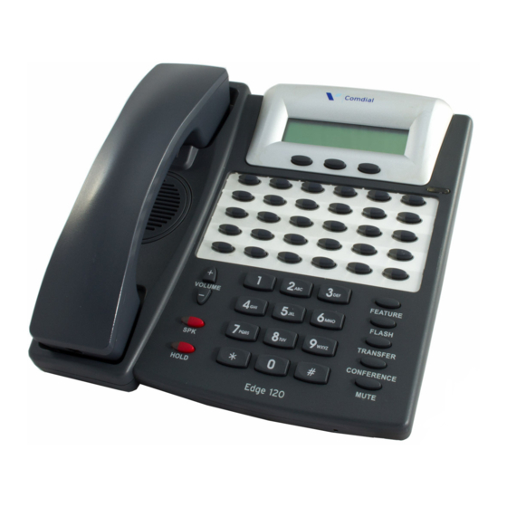
DX-120 Installation and Maintenance Manual VERVIEW DET (Digital Executive Telephone) The DX-120 has one model digital telephone called the Edge 120 Digital Executive Telephone. Edge 120 DET - Digital Extension Telephone • The DET provides: a speakerphone for hands-free conversations a two-row by sixteen column (32-character), dot-matrix, supertwist, Liquid Crystal Display (LCD) three interactive buttons to enhance system feature operation. -
Page 36: Dss (Direct Station Selection) Console
DX-120 Installation and Maintenance Manual VERVIEW DET - Digital Extension Telephone (continued) • Each DET is equipped standard with a 2.5 millimeter headset jack. Users can toggle their speakerphone operation in and out of a special “headset mode”. This mode allows the user to easily activate the headset jack via the ON/OFF button as an alternative to using the speakerphone. -
Page 37: Specifications
DX-120 Installation and Maintenance Manual VERVIEW DSS Console (continued) • The DSS has 64 programmable buttons with dual color (red / green) LEDs and may be assigned any system feature code or directory number. These buttons may be assigned for either system features operations or CO line access operations. - Page 38 DX-120 Installation and Maintenance Manual VERVIEW Specifications (continued) YSTEM RITERIA AND APACITY System Criteria and Capacity Time slots PCM - 32 time slots x 8 Highways (256 voice channels) TDM 64 Time Slots (data processing) Customer database memory protection 300 hours via on-board lithium battery (no charging required) Ports: CO/PBX/Centrex Lines Digital Stations...
- Page 39 DX-120 Installation and Maintenance Manual VERVIEW System Criteria and Capacity (continued) Voice Mail Groups 1 per Tenant (uses 1 UCD Group per VM system) Members (ports) Integration Method Digital (ICD Voice) and In-band (for other) VM message waiting #96 + station number to turn VM button LED on. VM control codes #*96 + station number to turn VM button LED off Disconnect Digits: 8 digits max.
- Page 40 DX-120 Installation and Maintenance Manual VERVIEW System Criteria and Capacity (continued) Message Waiting 40 simultaneous maximum per system (does not affect VM message indications) Name in Display 1 per station, 7 characters max. Class Of Service (COS) 8 (0-7) per Day, 8 (0-7) per Night Toll Restriction To/From Tables 100 Tables per tenant, 10 digits per entry, Day and Evening COS assignable per entry per CO Line and Extension.
- Page 41 DX-120 Installation and Maintenance Manual VERVIEW Specifications (continued) LECTRICAL Electrical Specifications AC Power source Dedicated 117/230vac + 15%, 47-63Hz single phase Power consumption 1.5A maximum @ 120vac (180 watts) Power Supply fuse AC input: 2A 250v DC output: 1A 125v Idle Channel Noise -74 dB Cross Talk Attenuation...
- Page 42 DX-120 Installation and Maintenance Manual VERVIEW Specifications (continued) OMPONENT ETAIL UNIT SPECIFICATIONS Part Number Description Dimensions: Weight 7200 CPM Central Processor Module 210 mm 8.25 in. 0.4Kg 138 mm 5.5 in. 18 mm .75 in. 7201P/7202P KSU1/KSU2 460 mm 18.4 in. 4.0Kg 270 mm 10.8 in.
- Page 43 DX-120 Installation and Maintenance Manual VERVIEW UNIT SPECIFICATIONS (continued) Part Number Description Dimensions: Weight 7270 CO DX HD 210 mm 8.25 in. 0.342Kg 138 mm 5.5 in. 21 mm .0875 in. 7271C CO DX FLASH 210 mm 8.25 in. 0.233Kg 138 mm 5.5 in.
- Page 44 DX-120 Installation and Maintenance Manual VERVIEW Specifications (continued) EGULATORY FCC Registration Numbers For systems configured for key system operation (each D6XTAI-40144-KF-T CO line appears on its own dedicated button). For systems configured for hybrid operation (CO lines D6XTAI-40145-MF-T may be accessed by dial codes and Pool/Loop buttons). IGNALING INTERNAL Audible Signals...
- Page 45 DX-120 Installation and Maintenance Manual VERVIEW Specifications (continued) MTBF (M ETWEEN AILURE Mean-Time Between Failure Analysis System Components Cabinet Assembly 86.0 Power Supply Unit 170.0 2,915.7 408M 11,407.3 DPM8 3560.8 DPM16 121,654.5 COM4 6,146.5 APM4 6,860.2 761.0 2,337.3 318,076.27 ISDN (T1/PRI) 257,340.64 Method: Use the figures above for each unit installed (or to be installed)
- Page 46 THIS PAGE INTENTIONALLY LEFT BLANK...
-
Page 47: Section 2 - Installation
SECTION 2 - INSTALLATION INSTALLING THE DX-120 Proper installation of the Vertical DX-120 is essential to assure optimum system operation. You must follow these procedures to reduce system problems resulting from improper installation and to reduce the potential of experiencing problems while bringing the DX-120 on-line. -
Page 48: Site Planning
DX-120 DX-120 Installation and Maintenance Manual NSTALLING THE Site Planning The first step in site planning is establishing suitable environmental conditions for the system. A) Place KSU1, and KSU2 if applicable, within 5 feet (1.5 meters) of an isolated, dedicated, 105-125VAC, 57-63Hz, 15A, single-phase commercial power source. -
Page 49: Tools And Supplies
26 AWG gauge minimum. Tools and Supplies Assemble the correct supplies and tools to install the Vertical DX-120. • Use UTP (Unshielded, Twisted-Pair) three or four pair (recommended) cable to run from the MDF to all extension terminals (DETs, DSS consoles, and analog devices). - Page 50 DX-120 DX-120 Installation and Maintenance Manual NSTALLING THE Preparing the Main Distribution Frame (continued) KSU C OMPONENTS AND NSTALLATION • KSU1 one mounting template standard 408M (module) equipped with eight digital extension ports, four CO line ports, and one CO line PFT (Power Failure Transfer) port standard CPM standard APM4...
- Page 51 DX-120 DX-120 Installation and Maintenance Manual NSTALLING THE Mounting the KSU (continued) 5) Extend the earth ground #10 wire into the KSU opening at the lower left corner of the KSU. 6) Terminate the grounding wire onto the ground lug provided there •...
-
Page 52: Ksu Wiring
The Siemon Company®, you are urged to investigate the various products available and make decisions for use based on your own assessment. Vertical is not responsible for the performance of any product provided by a third-party (outside) vendor. - Page 53 Therefore, Vertical does not recommend this method of installation. Since the Vertical DX-120 is equipped with RJ-11 interfaces for all port connections*, it is possible to route station cables into the KSU directly without use of 66M1-50 connector blocks. Using quality modular connectors and crimping tool, connect each terminal cable directly to the port required.
-
Page 54: Typical Mdf Installation
DX-120 DX-120 Installation and Maintenance Manual NSTALLING THE Typical MDF Installation The following example install illustrates a two-cabinet installation using the MDF installation method. Dedicated AC outlet “Station” cables (i.e., the dedicated from telephones outlet must have no other equipment connected to it on this circuit breaker). -
Page 55: Ksu Components
DX-120 DX-120 Installation and Maintenance Manual NSTALLING THE KSU Components KSU1, 408M KSU2 408E The 408M module is installed at the factory into KSU1. Although this module has the same port configuration as the 408E, they are not interchangeable. Each 408M and 408E is equipped with four CO line ports, one power failure port, and eight digital extension Ports. - Page 56 408E EPLACING A Occasionally, when instructed to do so by a Vertical technical support representative, you may have to remove a 408M or 408E and replace it in the field. To do so, use the following the steps. 1) Be sure that the entire system is turned off.
- Page 57 DX-120 DX-120 Installation and Maintenance Manual NSTALLING THE KSU Components (continued) KSU A – A SSEMBLY ODULES • Whenever you expand the DX-120 system, you install a module into one of the KSU cabinets. • Modules are connected to the various connectors on the 408M/E. •...
- Page 58 Circuit boards are susceptible to damage caused by electrostatic discharge. You must keep this in mind as you handle the circuit boards. For additional information, see Vertical publication IMI01-005, Handling of Electrostatically Sensitive Components. 6) Remove the DPM8 module from the packaging and locate the four brass-color standoffs packaged with the module.
- Page 59 NOTE When installing DPM8 modules, Vertical recommends that you install them closest to the 408M/E. That is, if an APM4 module is installed move it outward (toward cabinet cover) and install the add-on DPM8 first, then re-install the APM4.
-
Page 60: Adding An Apm4
DX-120 DX-120 Installation and Maintenance Manual NSTALLING THE Adding an APM4 You can add one APM4 to KSU1 and two APM4’s to the KSU2. These modules expand the DX-120 system capacity to a maximum of eight analog ports in each KSU (16 total analog ports when used in both KSU1 & KSU2). •... - Page 61 Circuit boards are susceptible to damage caused by electrostatic discharge. You must keep this in mind as you handle the circuit boards. For additional information, see Vertical publication IMI01-005, Handling of Electrostatically Sensitive Components. 6) Remove the APM4 module from the packaging and locate the four nickel-color standoffs packaged with the module.
-
Page 62: Adding A Com4
DX-120 DX-120 Installation and Maintenance Manual NSTALLING THE Installing the APM4 (continued) 9) Connect the APM4 ribbon cable to the 408M/E Extension Expansion Module Connector closest to the APM4. OR - FOR KSU2 In KSU2, connect the dedicated APM4 ribbon cable from the 408E to the APM4 module (and discard the packaged ribbon cable). - Page 63 For additional information, see Vertical publication IMI01-005, Handling of Electrostatically Sensitive Components. IMPORTANT! Vertical recommends installing the COM4 closest to the 408M/E. This means you must temporarily remove the CPM and then reposition the CPM above the COM4 once you have installed the COM4 (in KSU1).
-
Page 64: Adding An Mdm
DX-120 DX-120 Installation and Maintenance Manual NSTALLING THE Installing the COM4(continued) For KSU2 installation, skip step 12 and proceed to step 13. 12) Reposition the CPM over the installed COM4 and secure using the four brass-color standoffs previously removed (see page 57). - Page 65 Circuit boards are susceptible to damage caused by electrostatic discharge. You must keep this in mind as you handle the circuit boards. For additional information, see Vertical publication IMI01-005, Handling of Electrostatically Sensitive Components. 6) Locate the CPM at the right-hand side of KSU1, above the 408M (and COM4 if installed).
-
Page 66: Adding An Aam
Circuit boards are susceptible to damage caused by electrostatic discharge. You must keep this in mind as you handle the circuit boards. For additional information, see Vertical publication IMI01-005, Handling of Electrostatically Sensitive Components. 6) Locate the CPM at the right-hand side of KSU1 above the 408M (and COM4 if installed). -
Page 67: Adding A Ksu2 Second Cabinet
Circuit boards are susceptible to damage caused by electrostatic discharge. You must keep this in mind as you handle the circuit boards. For additional information, see Vertical publication IMI01-005, Handling of Electrostatically Sensitive Components. 6) Locate the long cable attached to the 408E of KSU2, and route it out of the KSU2 cabinet into the KSU1 cabinet so you can connect it to the CPM. - Page 68 DX-120 DX-120 Installation and Maintenance Manual NSTALLING THE Installing the KSU2 (continued) 8) Position the KSU2 connection cable over the CPM-“2 Cabinet Connector” as shown below. 2nd Cabinet Connector Cable from KSU2-408E HINT Press firmly (but not forcefully) on the KSU2-Cable connector to secure a good connection into the CPM-2 Cabinet Connector.
-
Page 69: Adding A Music Source
Circuit boards are susceptible to damage caused by electrostatic discharge. You must keep this in mind as you handle the circuit boards. For additional information, see Vertical publication IMI01-005, Handling of Electrostatically Sensitive Components. 6) Locate the CPM and “MUSIC” option strap. - Page 70 CAUTION 6.Circuit boards are susceptible to damage caused by electrostatic discharge. You must keep this in mind as you handle the circuit boards. For additional information, see Vertical publication IMI01-005, Handling of Electrostatically Sensitive Components. 6) Locate the CPM and the “MUSIC” option strap.
-
Page 71: Adding An External Pager
CAUTION 7.Circuit boards are susceptible to damage caused by electrostatic discharge. You must keep this in mind as you handle the circuit boards. For additional information, see Vertical publication IMI01-005, Handling of Electrostatically Sensitive Components. 6) Locate the CPM and “PAGE” connector jack on the CPM. -
Page 72: Add A Loud Bell Control Or Gate Control
Circuit boards are susceptible to damage caused by electrostatic discharge. You must keep this in mind as you handle the circuit boards. For additional information, see Vertical publication IMI01-005, Handling of Electrostatically Sensitive Components. 6) Locate the CPM and “BELL” connector jack on the CPM. - Page 73 Circuit boards are susceptible to damage caused by electrostatic discharge. You must keep this in mind as you handle the circuit boards. For additional information, see Vertical publication IMI01-005, Handling of Electrostatically Sensitive Components. 6) Locate the CPM and “BELL” connector jack on the CPM.
-
Page 74: Adding A Dpm16 (Digital Port Module - 16 Port)
7) Position the DPM16 over the left-hand side of the 408M/E and any other extension modules already installed. NOTE When installing DPM16 modules, Vertical recommends that you install them closest to the 408M/E. That is, if an APM4 module is installed move it outward (toward cabinet cover) and install the add-on DPM16 first, then re-install the APM4. -
Page 75: Adding A T1 Or Isdn (T1/Pri) Card
8) Position the T1 Card over the right-hand side of the 408M/E (and the COM4 module if it is installed). NOTE When installing a T1 Card module, Vertical recommends that you install it directly below the CPM card. Installing T1 or ISDN (T1/PRI) Card (continued on next page) -
Page 76: Connecting A Serial Cable For Pc-Dba
Circuit boards are susceptible to damage caused by electrostatic discharge. You must keep this in mind as you handle the circuit boards. For additional information, see Vertical publication IMI01-005, Handling of Electrostatically Sensitive Components. Installing T1 or ISDN (T1/PRI) Card (continued on next page) -
Page 77: Connecting A Serial Cable For Smdr
DX-120 DX-120 Installation and Maintenance Manual NSTALLING THE Installing T1 or ISDN (T1/PRI) Card (continued) 6) Locate the CPM and “PCDBA” serial port on the CPM. “PCDBA” serial port connector (straight-through, 9-pin, male-to-female cable required) 7) Connect the male end of the 9-pin serial cable into this PCDBA port. 8) Connect the other end (female) of the 9-pin serial cable to the PC serial port to be used with PC-DBA. -
Page 78: Power-Up Initialization (Cold Start)
Circuit boards are susceptible to damage caused by electrostatic discharge. You must keep this in mind as you handle the circuit boards. For additional information, see Vertical publication IMI01-005, Handling of Electrostatically Sensitive Components. 6) Locate the CPM and “SMDR” serial port on the CPM. - Page 79 Circuit boards are susceptible to damage caused by electrostatic discharge. You must keep this in mind as you handle the circuit boards. For additional information, see Vertical publication IMI01-005, Handling of Electrostatically Sensitive Components. in bottom right corner) of the 6) Locate the CPM and “NORMAL/COLD START”...
- Page 80 8) Move the strap to the “NORMAL” position. CAUTION Vertical ships the DX-120 with the option strap in the COLD START position to preserve the battery while the system is in transit. However, you MUST move this strap to NORMAL for the DX-120 to begin normal operation. The system specifically monitors the position of this strap and shuts down operation if it remains in the COLD START position.
-
Page 81: Section 3 - Maintenance & Troubleshooting
SECTION 3 - MAINTENANCE & TROUBLESHOOTING SYSTEM MAINTENANCE Maintaining the Vertical DX-120 digital telephone system is a combination of customer database changes, facilities and apparatus moves, adds and changes. These requirements are accomplished by practicing the techniques, illustrations and step-by-step instructions listed in the previous sections of this manual. -
Page 82: Diagnostic Quick Reference
DX-120 Installation and Maintenance Manual ECHNICAL ROBLEM OLUTIONS Technical Problem Solutions (continued) Diagnostic Quick Reference This section attempts to provide you with some quick, and reliable, tools to diagnose service-related problem reports. For installation-related problems, see “Troubleshooting Installation ISSUES”. Diagnostic Quick Reference Chart Symptom(s) Diagnostic Aid Cause(s) - Page 83 DX-120 Installation and Maintenance Manual ECHNICAL ROBLEM OLUTIONS Diagnostic Quick Reference Chart (continued) Symptom(s) Diagnostic Aid Cause(s) Action No system operation (continued) SPI Bus Error 1) Switch KSU power to the OFF position. 2) Remove cover (four screws). 3) Locate each expansion module. 4) Verify the ribbon cable connection is accurate and secure.
- Page 84 DX-120 Installation and Maintenance Manual ECHNICAL ROBLEM OLUTIONS Diagnostic Quick Reference Chart (continued) Symptom(s) Diagnostic Aid Cause(s) Action Digital telephone Digital Volt/Ohm Cable distance is If a digital telephone is not receiving clear 2B+D erratic operation: Meter too long for gauge of signaling from the KSU, test as follows: wire/cable used.
- Page 85 DX-120 Installation and Maintenance Manual ECHNICAL ROBLEM OLUTIONS Diagnostic Quick Reference Chart (continued) Symptom(s) Diagnostic Aid Cause(s) Action Cannot hear other Another digital Component failure 1) Lift handset connected party telephone If the intercom dial tone is not heard over the handset: 2) Hang up (put the handset in the cradle).
- Page 86 DX-120 Installation and Maintenance Manual ECHNICAL ROBLEM OLUTIONS Diagnostic Quick Reference Chart (continued) Symptom(s) Diagnostic Aid Cause(s) Action No sound heard Another digital Connection / 1) Press the SPK button. over loudspeaker telephone component failure 2) Listen for dial tone over the loudspeaker. in speakerphone 3) Call a working extension.
- Page 87 DX-120 Installation and Maintenance Manual ECHNICAL ROBLEM OLUTIONS Diagnostic Quick Reference Chart (continued) Symptom(s) Diagnostic Aid Cause(s) Action Static and / or noise can be heard during a conversation (continued) Telco problem If static/noise is heard on CO lines only: 1) Determine if other extensions also hear the noise/static.
-
Page 88: Maintenance Utilities
Loading PC-DBA software When PC-DBA is retrieved from Vertical’s web site, it is downloaded in a self-extracting executable file. Take the following actions to install the software on your PC. 1) Download the PC-DBA executable file from either the CD provided or from the CCC (go to www.vertical.com/ccc). -
Page 89: Connecting To The System
DX-120 Installation and Maintenance Manual ONNECTING TO THE YSTEM CONNECTING TO THE SYSTEM All operations in PC-DBA – Maintenance require that your PC be connected to the DX-120 switch. You can do this in any of three ways: • a direct connection to the KSU1 – CPM – PC-DBA port •... -
Page 90: Connecting Pc-Dba To The Dx-120 Switch
DX-120 Installation and Maintenance Manual ONNECTING TO THE YSTEM Connecting PC-DBA to the DX-120 Switch In order to use any of the Maintenance options available in PC-DBA, you must first connect it with the DX-120 switch. There are two methods that allow you to make this connection: •... - Page 91 DX-120 Installation and Maintenance Manual ONNECTING TO THE YSTEM Establishing a Local Connection with PC-DBA (continued) 6) Click Connect to initiate the connection. HINT When the system is connected a red dot will appear in the lower left corner of the screen next to the CTS indicator.
-
Page 92: Establishing A Modem Connection With Pc-Dba
DX-120 Installation and Maintenance Manual ONNECTING TO THE YSTEM Establishing a Modem Connection with PC-DBA If the system is not equipped with an automated attendant or a voice mail in auto attendant mode, make sure the attendant is aware that a modem connection will be taking place. Use of the automated attendant can greatly assist the modem connection process since you can enter the modem extension remotely. - Page 93 DX-120 Installation and Maintenance Manual ONNECTING TO THE YSTEM Establishing a Modem Connection with PC-DBA (continued) 6) Select the appropriate control string Enter a new control string. NOTE • To add a new control string: Enter a new control string, then click Add to List to save the new information.
-
Page 94: Accessing Pc-Dba Maintenance
PC-DBA M DX-120 Installation and Maintenance Manual CCESSING AINTENANCE ACCESSING PC-DBA MAINTENANCE The ability access the PC-DBA Maintenance Utilities requires the following two tasks: • Download of the PC-DBA software onto a PC • Sucessful and current connection between PC-DBA and the DX-120 processor From the main PC-DBA Screen: 1) Go to Maintenance to display a list of features. -
Page 95: Maintenance Utilities (Menu Items)
PC-DBA M DX-120 Installation and Maintenance Manual CCESSING AINTENANCE Maintenance Utilities (Menu Items) • Configuration (see below) • Diagnosis • Status • SW/HW Revision • Event • Logon Data • Remote Control • T1 Maintenance IMPORTANT! • Remember, in order to access these utilities, there must be an active connection between PC-DBA and the DX-120 switch (see See “Connecting PC-DBA to the DX-120 Switch”... - Page 96 PC-DBA M DX-120 Installation and Maintenance Manual CCESSING AINTENANCE Configuration (continued) EXAMPLE Click the X at the top right of each screen to close them. Click any of the buttons to display configuration Each time you click a information for each button, configuration of the information for the...
- Page 97 “Test Report” option - see “Run the Self Test Report Only” on page 95). IMPORTANT! When invoking the test for the entire system, Vertical recommends that you not select the “Wait for Result” option as this option takes several minutes to complete.
- Page 98 PC-DBA M DX-120 Installation and Maintenance Manual CCESSING AINTENANCE Diagnostics (continued) SELF TEST BOARDS You can run a self test and obtain report results for each the boards on your system. This test will let you know which boards are installed and working. Unlike the system self test, you will get the results immediately following the test.
- Page 99 PC-DBA M DX-120 Installation and Maintenance Manual CCESSING AINTENANCE Self Test Boards (continued) 4) Click Go to display the results for the specified board. • You can review results for each board one at a time. Use the scroll bar to view all of the results.
- Page 100 PC-DBA M DX-120 Installation and Maintenance Manual CCESSING AINTENANCE Self Test Ports (continued) • The port Select screen will appear. 3) Click the arrow at the right of the field to display a list of the ports that were included in the test. Click the arrow here to display the list of ports that were included in the...
- Page 101 PC-DBA M DX-120 Installation and Maintenance Manual CCESSING AINTENANCE Diagnostics (continued) RUN THE SELF TEST REPORT ONLY If you ran a Self Test, but did not want to wait for results, or simply need to review the results of the last tests run, you can use this option.
- Page 102 PC-DBA M DX-120 Installation and Maintenance Manual CCESSING AINTENANCE Maintenance Utilities (continued) TATUS You can use the Status function to view a specific DX-120 system resource status (e.g., On the Status - OPTION BOARD screen the connect status can be either IDLE (ready for call) or BUSY (port in use). From the main PC-DBA Screen (during connection between the system and the switch - see page 84): 1) Go to Maintenance Status to display the Status screen.
- Page 103 PC-DBA M DX-120 Installation and Maintenance Manual CCESSING AINTENANCE Status (continued) To Get the Status of the CPM Board 2) Click the CPM Board button to display the status of the RS232 ports (then skip to step 5 on page 98).
- Page 104 PC-DBA M DX-120 Installation and Maintenance Manual CCESSING AINTENANCE Status (continued) To Find Out Which Slots are Open 4) Click Open for either Cabinet 1 or 2 to see which slots in the specified cabinet are available (or that have no hardware recognized). •...
- Page 105 PC-DBA M DX-120 Installation and Maintenance Manual CCESSING AINTENANCE Maintenance Utilities (continued) SW/HW R EVISION You can use the SW/HW Revision to view the current version of software and firmware of the boards installed in the DX-120. The Hardware Revision (HW Revision) is a label only field that allows the user of PC-DBA to record the revision of hardware installed at the site.
- Page 106 PC-DBA M DX-120 Installation and Maintenance Manual CCESSING AINTENANCE SW/HW Revision (continued) IMPORTANT! • Once you receive the information into the PC-DBA, then click Save, the information will appear any time you open this screen. However, you will need to perform a SEND to update any revisions that may have been made. 2) Edit information as needed.
- Page 107 PC-DBA M DX-120 Installation and Maintenance Manual CCESSING AINTENANCE Event (continued) EVENT INVOKING (SETTING THE SYSTEM FOR SPECIFIC EVENT TRACKING) From the main PC-DBA Screen (during connection between the system and the switch - see page 84): 1) Go to Maintenance Event Event Invoking to display the Event screen. IMPORTANT! If at this point you get a “DOUBLE INVOKING!”...
- Page 108 PC-DBA M DX-120 Installation and Maintenance Manual CCESSING AINTENANCE Event Invoking (continued) 2) Click on the + next to one of the operations to expand the list. EXAMPLE Click a plus sign (+) to expand the list. 3) Select one of the available system operations that will cause event data output to begin. IMPORTANT! Do not select “Pseudo”...
- Page 109 PC-DBA M DX-120 Installation and Maintenance Manual CCESSING AINTENANCE Event Invoking (continued) EXAMPLE Click here to move the selected operation into the Start Event field. 5) Select one of the available system operations that will cause event data output to end (stop). EXAMPLE Select a stopping event.
- Page 110 PC-DBA M DX-120 Installation and Maintenance Manual CCESSING AINTENANCE Event Invoking (continued) 7) Click on Invoke to set the designated event tracking. • A message will appear to let you know the settings are being invoked. EVENT DELETING Once you invoke a set of Event Tracking criteria, you will need to delete those before setting new ones. From the main PC-DBA Screen (during connection between the system and the switch - see page 84): 1) Go to Maintenance Event Event Deleting to delete any event tracking settings.
- Page 111 Block system resources for the purposes of maintenance operations (Block Control) DIRECTORY MEMORY MAPPING Use Directory Memory Mapping when instructed to do so by a Vertical technical support representative. CAUTION The Engineering Maintenance Tools should only be used by trained personnel.
- Page 112 PC-DBA M DX-120 Installation and Maintenance Manual CCESSING AINTENANCE Remote Control (continued) SOFTWARE WARM START Use Software Warm Start to cause the system to restart operations. CAUTION USE THIS FEATURE WITH CARE! This operation requires confirmation since all calls in progress will be disconnected. NOTE Once you run this operation, connection between the switch and PC-DBA will be lost.
- Page 113 PC-DBA M DX-120 Installation and Maintenance Manual CCESSING AINTENANCE Remote Control (continued) SOFTWARE COLD START Use Software COLD Start to cause the system to restart operations and reload default customer database data. CAUTION USE THIS FEATURE WITH CARE! This operation requires confirmation since all calls in progress will be disconnected and the current database will be erased! NOTE...
- Page 114 PC-DBA M DX-120 Installation and Maintenance Manual CCESSING AINTENANCE Maintenance Utilities (continued) BLOCK CONTROL You can use Block Control to restrict access to certain system resources for the purposes of trouble-shooting, e.g. you might block a CO line from use in order to test the circuit while avoiding user access to the CO line circuit. To use Block Control, you must know the cabinet number, board/module number and port number.
- Page 115 7) Click OK to close the window. I/O MEMORY MAPPING Use I/O Memory Mapping when instructed to do so by a Vertical technical support representative. This operation is used to view system input/output port values. CAUTION The Engineering Maintenance Tools should only be used by trained personnel.
- Page 116 PC-DBA M DX-120 Installation and Maintenance Manual CCESSING AINTENANCE Maintenance Utilities (continued) T1 M AINTENANCE The DX-120 provides an easy and efficient way to track and report errors that may occur during its operation. There are three tools that allow for tracking and clearing of errors: •...
- Page 117 2) Evaluate the errors and determine a course of action, if applicable. IMPORTANT! Contact Vertical Technical Support for assistance with understanding and correcting errors. 3) Click Refresh to get a real time listing of errors (registered since you previously ran the report.
- Page 118 You can clear specific errors or ALL errors. The default for this screen is for ALL options to be checked. IMPORTANT! Contact Vertical Technical Support for assistance with understanding and clearing errors. 1) Go to Maintenance T1 Maintenance Clear Errors to display the Clear Error screen. 2) Select any or all of the errors you want to clear.
-
Page 119: Section 4 - Installation Issues
DX-120 Installation and Maintenance Manual SECTION 4 - INSTALLATION ISSUES TROUBLESHOOTING INSTALLATION ISSUES This chapter outlines the most common installation problems for the DX-120, and provides a corrective action addressing each issue. Corrupted Database on Initial System Setup SOLUTION: DX-120 POWER-UP INITIALIZATION You must successfully initialize the DX-120 system during start up procedures for the system to operate properly. -
Page 120: Voice Mail Doesn't Work ("No Legal Member" Error)
ISSUES DX-120 Installation and Maintenance Manual ROUBLESHOOTING NSTALLATION Adding Hardware to an Existing System (continued) Adding New Hardware 1) Connect and login to PC-DBA. • See “Accessing PC-DBA Maintenance” on page 88 for more information about connecting to and accessing PC-DBA). 2) Press F3 to perform a a Receive All. - Page 121 ISSUES DX-120 Installation and Maintenance Manual ROUBLESHOOTING NSTALLATION Voice Mail Doesn’t Work - “No Legal Member” Error (continued) • If you have an existing database, and you have PC-DBA loaded onto a laptop, you can: save the customized database perform a cold start initialization (which loads a default database, writing over your custom database), and then reload the saved database over the default database.
- Page 122 ISSUES DX-120 Installation and Maintenance Manual ROUBLESHOOTING NSTALLATION What to Do if a Normal Cold Start/Restart Is Not Possible (continued) 12) Press HOLD to return to the previous menu level. Press the Up or Down Volume arrows to return to the database Item 13) Return to the Selection screen.
-
Page 123: Invalid Entries Calling A Busy Station (Issues With Multiple Mailbox Greetings)
ISSUES DX-120 Installation and Maintenance Manual ROUBLESHOOTING NSTALLATION Invalid Entries Calling a Busy Station (Issues with Multiple Mailbox Greetings) SOLUTION: THE FOLLOWING ITEMS SHOULD BE APPLIED TO ALL DX-120 (PC8 IN-SKIN) VOICE MAIL SYSTEMS; BUILD 8.5.9 AND EARLIER. 1) Add the new TRANS.TXT file – 8.5.9. NOTE •... -
Page 124: Ensuring Optimum Call Handling Performance
ISSUES DX-120 Installation and Maintenance Manual ROUBLESHOOTING NSTALLATION (continued) ;UCD overflow 1 for UCD groups 1-5 a9byd1=3101 a9byd2=3102 a9byd3=3103 a9byd4=3104 a9byd5=3105 ;UCD overflow 2 for UCD groups 1-5 a9byd91=3201 a9byd01=3202 a9byd*1=3203 a9byd#1=3204 a9byda1=3205 ;UCD overflow for all other groups a9bydx= 2) Remove Mail Box 157. -
Page 125: Ringing A Group Of Phones Before Routing The Call To Auto-Attendant
ISSUES DX-120 Installation and Maintenance Manual ROUBLESHOOTING NSTALLATION Ringing a Group Of Phones Before Routing the Call to Auto-Attendant SOLUTION: IMPLEMENT DELAYED RINGING TO VOICE MAIL, AUTO ATTENDANT NOTE UCD groups 1- 5 (410-414) are used for the DX-120’s built in UCD functionality with the In-skin Voice mail system. - Page 126 ISSUES DX-120 Installation and Maintenance Manual ROUBLESHOOTING NSTALLATION Implementing Delayed Ringing (continued) Set up the CO line Answering Position. 3) Make the specified UCD Group the only Destination for Day / Eve. 4) Set Pre-CFW NoAns to NULL. Implementing Delayed Ringing (continued on next page) - 120 -...
- Page 127 ISSUES DX-120 Installation and Maintenance Manual ROUBLESHOOTING NSTALLATION Implementing Delayed Ringing (continued) NSKIN OICE • If you use UCD groups 6 through 23, you do not have to modify TRANS.TXT unless you want a specific routing box or mailbox to answer. •...
-
Page 128: Using Multiple Lines & Assigning Different Auto-Attendant Greetings For Each Line
ISSUES DX-120 Installation and Maintenance Manual ROUBLESHOOTING NSTALLATION Using Multiple Lines & Assigning Different Auto-Attendant Greetings for Each Line SOLUTION: CO LINE ROUTING Both of the following examples will use: • Trunks 1-2 for Company A • Trunks 3-5 for Company B •... - Page 129 ISSUES DX-120 Installation and Maintenance Manual ROUBLESHOOTING NSTALLATION CO Line Routing - Example (continued) EXAMPLE (continued) 2) Assuming that: Company A will be using Routing Box 800 to answer incoming calls; Company B will use Routing Box 810, and Company C will use Routing Box 820. Add the following lines to the top of the TRANS.TXT file.
- Page 130 ISSUES DX-120 Installation and Maintenance Manual ROUBLESHOOTING NSTALLATION CO Line Routing - Example (continued) EXAMPLE (continued) The following line is needed at the top of the TRANS.TXT file. a9b2d63 = 800 The following UCD group 7 (dir 416) will ring all phones approximately three to four rings, then re-route to Voice Mail with the following in-band digits.
-
Page 131: Setting Up Message Delivery To A Cell Phone
ISSUES DX-120 Installation and Maintenance Manual ROUBLESHOOTING NSTALLATION Setting Up Message Delivery to a Cell Phone SOLUTION: USE REMOTE.EXE* FOR EXTERNAL TRANSFERS WITH VOICE MAIL • If the system has In-Skin or analog voice mail, and uses Centrex transfer on the same CO line: go to the Call Transfer Information screen in voicemail, then enter the following values in the External column. - Page 132 ISSUES DX-120 Installation and Maintenance Manual ROUBLESHOOTING NSTALLATION External Transfers with Voice Mail (continued) • ou must enable ECF. Go to the DX-120 Extension screen: Click on check box of the ECF Operation field to place a checkmark there (i.e., to enable the feature). NOTE If you are using the phone to program, and enter 01-XXX-18 (where XXX represents the station number).
-
Page 133: Using Prime Co Instead Of Intercom With Modem Or Fax
ISSUES DX-120 Installation and Maintenance Manual ROUBLESHOOTING NSTALLATION Using Prime CO Instead of Intercom with Modem or Fax SOLUTION: ANALOG PRIME LINE—SETTING UP A PRIME LINE FOR A FAX CONNECTED TO AN ANALOG PORT USING CO LINE 4. Place Line 4 (803) into CO Group2 (740) From the Fax Machine 1) Remove the receiver from the hook. - Page 134 ISSUES DX-120 Installation and Maintenance Manual ROUBLESHOOTING NSTALLATION Place Line 4 (803) into CO Group2 (740) from the Fax Machine (continued) Use the Telephone 6) Dial into the programming mode and enter the following commands. • FEATURE # * • Enter the password.
-
Page 135: Digits Passed Inband To The Voice Mail In An Overflow 1 Condition
ISSUES DX-120 Installation and Maintenance Manual ROUBLESHOOTING NSTALLATION Digits Passed Inband to the Voice Mail in an Overflow 1 Condition SOLUTION: UCD OVERFLOW 1 INTEGRATION TO VOICE MAIL The following table shows what the switch passes inband to the Voice Mail during an Overflow 1 condition. Overflow from UCD groups / In band Strings / Digits Received Associated VM Hunt Group #... -
Page 136: Digits Passed Inband To The Voice Mail In An Overflow 2 Condition
ISSUES DX-120 Installation and Maintenance Manual ROUBLESHOOTING NSTALLATION Digits Passed Inband to the Voice Mail in an Overflow 2 Condition SOLUTION: UCD OVERFLOW 2 INTEGRATION TO VOICE MAIL The following table shows what the switch passes inband to the Voice Mail during an Overflow 2 condition. OVERFLOW FROM UCD GROUPS / IN BAND STRINGS / DIGITS RECEIVED Associated VM Hunt Group #... -
Page 137: Digits Passed Inband To The Voice Mail In A Re-Route Condition
ISSUES DX-120 Installation and Maintenance Manual ROUBLESHOOTING NSTALLATION Digits Passed Inband to the Voice Mail in a Re-Route Condition SOLUTION: UCD RE-ROUTE INTEGRATION TO VOICE MAIL The following table shows what the switch passes inband to the Voice Mail during a re-route condition. TRANSFERRING TO UCD GROUPS / IN BAND STRINGS / DIGITS RECEIVED Hunt Group # UCD #... - Page 138 THIS PAGE INTENTIONALLY LEFT BLANK...
- Page 139 DX-120 Installation and Maintenance Manual INDEX Numerics 408E 19 Battery requirements 16 KSU2 49 Bell replacing 50 adding 66 408M 11, 18 installing 66 KSU1 49 Block control 108 replacing 50 Boards self test 92 AAM (Automated Attendant Module) 10, 25, 60 adding 60 Cable 83 installation 60...
- Page 140 DX-120 Installation and Maintenance Manual NDEX cable 83 local 84 modem 86 Electrical data 35 remote 84 Ensuring optimum call handling performance 118 Console, DSS 30 Environmental data 35 Control Error block 108 clear T1 112 door 67 T1 seconds 111 gate 66, 67 T1 threshold 110 remote 105...
- Page 141 DX-120 Installation and Maintenance Manual NDEX I/O Memory Mapping 109 Loading Initalization PC-DBA 82 software 82 cold start 72 power-up 72 Local connection 84 warm start 106 Logon data 105 Inskin voicemail 119, 121 Loud bell control installation 66 installation 41 AAM 60 add-on modules 51 APM4 54...
- Page 142 DX-120 Installation and Maintenance Manual NDEX MTBF (mean-time between failure) data 39 Multiple mailbox greetings 117 Music Registration numbers 38 adding source 63 Regulatory data 38 channel MC1 63, 64 Remote channel MC2 64 connection 84, 86 channel 1 17 control 105 channel 2 17 Remote Control 105...
- Page 143 DX-120 Installation and Maintenance Manual NDEX Start cold 107 warm 106 Unit (component) detail 36 Static Electricity 1 User maintenance 75 Status 96 Using multiple lines 122 Storage temperature 35 Using Prime CO Instead of Intercom with Modem or Fax 127 Supplies needed for installation 43 USOC Code 4 SW/HW Revision 99...
- Page 144 THIS PAGE INTENTIONALLY LEFT BLANK...
- Page 146 Copyright © 2006 Vertical Communications, Inc. All rights reserved. Unauthorized use of this document is prohibited. DX120L-IMM-1006...
Need help?
Do you have a question about the comdial DX-120 and is the answer not in the manual?
Questions and answers