
Related Manuals for MasterCraft 054-7240-8


Summary of Contents for MasterCraft 054-7240-8
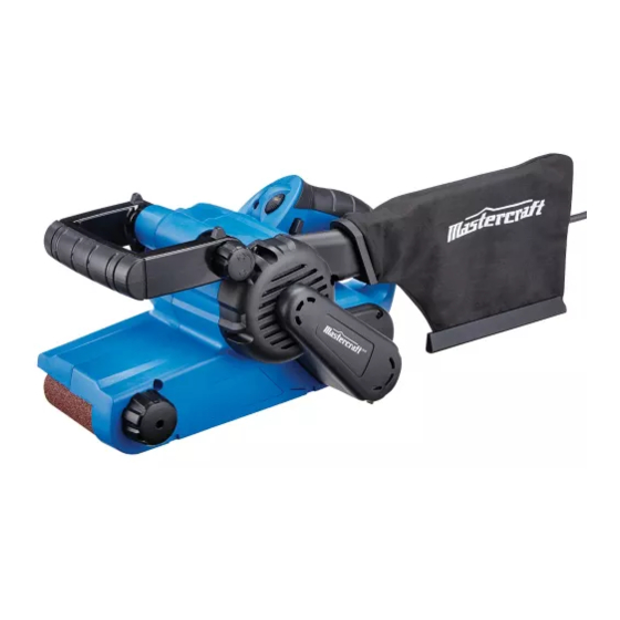
- Page 1 054-7240-8 3 X 21" BELT SANDER INSTRUCTION IMPORTANT: Read and understand this instruction manual thoroughly before MANUAL using the product.
- Page 2 headline bars continuation tabs notes warnings...
-
Page 3: Table Of Contents
TABLE OF CONTENTS Technical Specifications Safety Guidelines Key Parts Diagram Assembly Instructions Operating Instructions Maintenance Troubleshooting Part list Warranty NOTE: If any parts are missing or damaged, or if you have any questions, please call our toll-free helpline at 1-800-689-9928 SAVE THESE INSTRUCTIONS •... -
Page 4: Technical Specifications
054-7240-8 | contact us 1.800.689.9928 TECHNICAL SPECIFICATIONS Rated voltage 120V~, 60Hz Rated power input 6.0 A Belt speed 0–1100 ft/min Belt size 3 x 21" Net weight 7 lb 1 oz (3.2 kg) continuation tabs notes... -
Page 5: Safety Guidelines
RULES FOR SAFE OPERATION WARNING! Safety symbols in this Instruction Manual are used to flag possible dangers. The safety symbols and their explanations require your full understanding. The safety warnings do not, by themselves, eliminate any danger, nor are they substitutes for proper accident prevention measures. - Page 6 054-7240-8 | contact us 1.800.689.9928 ELECTRICAL SAFETY • Power tool plugs must match the outlet. Never modify the plug in any way. Do not use any adapter plugs with earthed (grounded) power tools. Unmodified plugs and matching outlets will reduce risk of electric shock.
- Page 7 • Do not use the power tool if the switch does not turn it on and off. Any power tool that cannot be controlled with the switch is dangerous and must be repaired. • Disconnect the plug from the power source and/or the battery pack from the power tool before making any adjustments, changing accessories, or storing power tools.
- Page 8 054-7240-8 | contact us 1.800.689.9928 ....Grounding terminal BPM ....Beats per minute ....WARNING – To reduce the risk of injury, user must read instruction manual....WARNING – To reduce the risk of injury always wear eye protection.
-
Page 9: Key Parts Diagram
PACKAGE CONTENTS Belt sander, dust bag, fine belt, coarse belt and instruction manual KEY PARTS DIAGRAM Part Part ON/OFF 2-finger trigger switch Belt adjustment knob “Lock-ON” button 3-position adjustable handle Adjustable belt speed knob Cord guard Quick release tension lever Dust collection bag Sander belt WARNING! -
Page 10: Assembly Instructions
054-7240-8 | contact us 1.800.689.9928 ASSEMBLY INSTRUCTIONS SANDER BELT (fig 1) fig 1 To install belt: 1. Place sander on its side and pull the quick release tension lever out, as shown in fig 1. - Page 11 BELT ADJUSTMENT KNOB (fig 2) fig 2 Your sander features an automatic belt-control system that helps to keep the belt running in the centre of the rollers. The system has been preset at the factory, but may require adjustment to avoid frayed belt edges and wear on the sander frame when a belt is changed or an older belt stretches.
-
Page 12: Operating Instructions
054-7240-8 | contact us 1.800.689.9928 OPERATING INSTRUCTIONS TURNING THE SANDER ON AND OFF The tool can be turned “ON” or “OFF” by squeezing or releasing the trigger. “LOCK-ON” BUTTON 1. The tool is also equipped with a “Lock-ON” button that allows continuous operation without continually holding the trigger. -
Page 13: Maintenance
MAINTENANCE Before cleaning or performing any maintenance, make sure the sander has been disconnected from the power supply. Keep all ventilation openings clean. Avoid using solvents when cleaning plastic parts. Most plastics are susceptible to damage from various types of commercial solvents and may be damaged by their use. -
Page 14: Troubleshooting
054-7240-8 | contact us 1.800.689.9928 TROUBLESHOOTING Problem Possible Causes Solution The belt sander does not The sander is not connected to Connect the plug to a power source work a power source If any parts are missing or damaged, or if you have any questions, please call the Toll-free Helpline, at 1-800-689-9928. - Page 15 EXPLODED VIEW...
- Page 16 054-7240-8 | contact us 1.800.689.9928 Part No. Description Part No. Description 2740085000 Stator 3660131000 Spring 2750093000 Rotor 3660242000 Spring 2800026000 Brush Holder 3700145000 Washer A 2820230000 Bracket Assembly 3700183000 Washer C 2820334000 Internal Wire Assembly 1...
- Page 17 This Mastercraft product is guaranteed for a period of 3 years from the date of original retail purchase against defects in workmanship and materials, except for the following components: a) Component A: Batteries, chargers and carrying case, which are guaranteed for a period of 2 years from the date of original retail purchase against defects in workmanship and materials;...
- Page 18 054-7240-8 | contact us 1.800.689.9928 h) this warranty will not apply to normal deterioration of the exterior finish, such as, but not limited to, scratches, dents, paint chips, or to any corrosion or discolouring by heat, abrasive and chemical cleaners;...
- Page 19 model no. 054-6602-4 PLANER INSTRUCTION IMPORTANT: Read and understand this instruction manual thoroughly before MANUAL using the product.
- Page 20 headline bars continuation tabs notes warnings...
-
Page 21: Part List
TABLE OF CONTENTS Technical Specifications Safety Guidelines 5–8 Key Parts Diagram 9–10 Important Information 11–12 Assembly Instructions 13–14 Operating Instructions 15–17 Maintenance 18–20 Troubleshooting Part list 22–23 Warranty 24–25 NOTE: If any parts are missing or damaged, or if you have any questions, please call our toll-free helpline at 1-800-689-9928 SAVE THESE INSTRUCTIONS •... -
Page 22: Technical Specifications
headline bars model no. 054-6602-4 | contact us 1.800.689.9928 TECHNICAL SPECIFICATIONS Input 6.0 A Rating 120V~, 60Hz No load speed 17,000 RPM Planing capacity: Planing width 3 1/4" (8.2 cm) continuation tabs Planing depth 0–1/8" (0–3.0 mm) Rabbetting depth 1/2" (12.7 mm) Tool weight 6 lb 3 oz (2.8 kg) Level of vibration a... -
Page 23: Safety Guidelines
RULES FOR SAFE OPERATION WARNING! Safety symbols in this Instruction Manual are used to flag possible dangers. The safety symbols and their explanations require your full understanding. The safety warnings do not, by themselves, eliminate any danger, nor are they substitutes for proper accident prevention measures. WARNING! This Safety Alert Symbol indicates caution, warning, or danger. -
Page 24: Power Tool Use And Care
headline bars model no. 054-6602-4 | contact us 1.800.689.9928 ELECTRICAL SAFETY • Power tool plugs must match the outlet. Never modify the plug in any way. Do not use any adapter plugs with earthed (grounded) power tools. Unmodified plugs and matching outlets will reduce risk of electric shock. - Page 25 • Disconnect the plug from the power source and/or the battery pack from the power tool before making any adjustments, changing accessories, or storing power tools. Such preventive safety measures reduce the risk of starting the power tool accidentally. • Store idle power tools out of the reach of children and do not allow persons unfamiliar with the power tool or these instructions to operate the power tool.
- Page 26 headline bars headline bars model no. 054-6602-4 | contact us 1.800.689.9928 SAFETY GUIDELINES FOR PLANER • Wait for the cutter to stop before setting the tool down. An exposed, rotating cutter may engage the surface and result in possible loss of control and serious injury. •...
-
Page 27: Key Parts Diagram
PACKAGE CONTENTS Planer, edge guide, blade change wrench (installed on the planer), rabbetting depth scale, dust bag, vacuum adaptor and instruction manual. KEY PARTS DIAGRAM WARNING! • Remove the planer from the package and examine it carefully. Do not discard the carton or any packaging material until all parts have been examined. - Page 28 headline bars headline bars model no. 054-6602-4 | contact us 1.800.689.9928 Part Part On/off trigger switch Clamping element Lock-off button Clamping screw Depth-adjustment knob Adjustable front base Handle Fixed rear base Dust/chip extraction port Edge guide Edge-guide attachment knob Rabbetting depth stop continuation tabs continuation tabs Dust/chip extraction guide switch...
-
Page 29: Important Information
IMPORTANT INFORMATION Before attempting to use this tool, become familiar with all of its operating features and safety requirements. For optimum performance and safety, read the following operating instructions carefully before using. DUST/CHIP EXTRACTION GUIDE fig 1 SWITCH (fig 1) Moving the switch to the left of the tool will cause chips to be discharged to the right;... - Page 30 headline bars headline bars model no. 054-6602-4 | contact us 1.800.689.9928 BLADE CHANGE WRENCH STORAGE fig 4 AREA (fig 4) Your tool is equipped with a blade wrench that is conveniently located in the handle base where it is always handy and unlikely to get lost or misplaced. TOOL PARK REST The park rest swings down to help keep the blade from continuation tabs...
-
Page 31: Assembly Instructions
ASSEMBLY INSTRUCTIONS EDGE GUIDE fig 6 1. To attach the edge guide, remove the edge-guide attachment knob and slide the edge guide into the planer. 2. Replace the edge-guide attachment knob and firmly tighten it (fig 6). 3. Loosen the locking nut and slide the edge guide to the desired position. - Page 32 headline bars headline bars model no. 054-6602-4 | contact us 1.800.689.9928 SETTING THE RABBETTING DEPTH 1. Loosen rabbetting depth-stop locking nut and set the desired rabbet depth by aligning the depth scale on the rabbetting depth stop with the indicator line. 2.
-
Page 33: Operating Instructions
OPERATING INSTRUCTIONS SWITCHING ON AND OFF (fig 10) fig 10 1. Connect the power cord of your planer to a standard household power outlet. 2. To turn the planer ON, hold the tool with both hands, push in the lock-off button first, and then press the on/off trigger switch. - Page 34 headline bars model no. 054-6602-4 | contact us 1.800.689.9928 PLANING (fig 11) fig 11 1. Unplug the planer and adjust the edge guide and cutting depth as appropriate. 2. Clamp the workpiece securely on a workbench, 3. Connect the power cord of your planer to a standard household power outlet.
- Page 35 PLANING WITH THE EDGE GUIDE fig 12 The edge guide can be used to control the width of the cut or for simply providing added stability and protection when cutting materials that are up to 3-1/4" (82 mm) wide (fig 12). 12.7 mm CHAMFERING (fig 13) The “V”...
-
Page 36: Maintenance
headline bars headline bars model no. 054-6602-4 | contact us 1.800.689.9928 MAINTENANCE BEFORE EACH USE 1. Inspect the planer, the trigger switch, the cord and the accessories for damage. 2. Check for damaged, missing, or worn parts. 3. Check for loose screws, misalignment or binding of moving parts, or any other condition that may affect the operation. - Page 37 REPLACING THE PLANER BLADES fig 14 REMOVING THE OLD PLANER BLADES 1. Disconnect the plug from the power source. 2. Place the planer upside down on a flat surface. 3. Loosen the three clamping screws with the wrench that is provided (fig 14). 4.
-
Page 38: Drive Belt
headline bars headline bars model no. 054-6602-4 | contact us 1.800.689.9928 DRIVE BELT The drive belt is a normal maintenance part and should be inspected periodically for wear. If the drive belt shows signs of drying out, cracking or tearing, it should be replaced. If the drive belt will not track properly or comes off the pulleys, it should be replaced. -
Page 39: Troubleshooting
TROUBLESHOOTING Problem Possible Causes Solution 1. The tool is not connected to a 1. Connect the tool to a power source power source The motor does not start 2. The lock-off button is not 2. Press down the lock-off button and depressed before squeezing the hold it, then depress the trigger on/off trigger switch... - Page 40 headline bars headline bars model no. 054-6602-4 | contact us 1.800.689.9928 EXPLODED VIEW continuation tabs continuation tabs notes notes warnings warnings...
- Page 41 No. Part No. Description No. Part No. Description 054660201 Front Sole Plate 054660229 Backplane Positioning Bar 054660202 Big Spring 054660230 Spring 054660203 Steel Ball 054660231 Support 054660204 Spring 054660232 Backplane 054660205 Scale 054660233 Screw 054660206 Scale Support 054660234 Fari Baffel 054660207 Knob Base 054660235...
- Page 42 This Mastercraft product is guaranteed for a period of 3 years from the date of original retail purchase against defects in workmanship and materials, except for the following components: a) Component A: Batteries, chargers and carrying case, which are guaranteed for a period of 2 years from the...
- Page 43 This warranty gives you specific legal rights, and you may have other rights, which may vary from province to province. The provisions contained in this warranty are not intended to limit, modify, take away from, disclaim or exclude any statutory warranties set forth in any applicable provincial or federal legislation. IMPORTED BY MASTERCRAFT CANADA TORONTO, CANADA M4S 2B8...
Need help?
Do you have a question about the 054-7240-8 and is the answer not in the manual?
Questions and answers