Table of Contents

Subscribe to Our Youtube Channel
Related Manuals for KYLAND Technology SICOM3024P


Summary of Contents for KYLAND Technology SICOM3024P
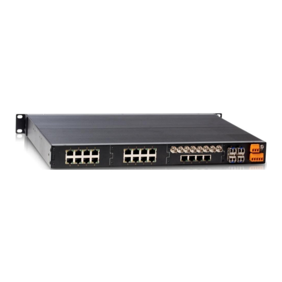
- Page 1 SICOM3024P/SICOM3048/SICOM3024 Series Industrial Ethernet Switches Web Operation Manual Kyland Technology Co., Ltd. Publication Date: Sep. 2013 Version: V2.2 FAX: +86-10-88796678 Website: http://www.kyland.com E-mail: support@kyland.com...
- Page 2 Disclaimer: Kyland Technology Co., Ltd. tries to keep the content in this manual as accurate and as up-to-date as possible. This document is not guaranteed to be error-free, and we reserve the right to amend it without notice. Copyright © 2013 Kyland Technology Co., Ltd.
-
Page 3: Table Of Contents
Contents Preface ..........................1 1 Product Introduction ......................5 1.1 Overview ........................5 1.2 Product Models ......................5 1.3 Software Features ......................5 2 Switch Access ........................7 2.1 View Types ........................7 2.2 Access through Console Port ..................8 2.3 Access through Telnet.................... - Page 4 6.1.3 Typical Configuration Example ................32 6.2 VLAN .......................... 32 6.2.1 Overview ......................32 6.2.2 Principle ........................ 32 6.2.3 Port-based VLAN....................33 6.2.4 Web Configuration ....................34 6.2.5 Typical Configuration Example ................38 6.3 PVLAN ........................39 6.3.1 Overview ......................39 6.3.2 Web Configuration ....................
- Page 5 6.8.5 Typical Configuration Example ................54 6.9 ACL ..........................55 6.9.1 Overview ......................55 6.9.2 Implementation ..................... 55 6.9.3 Web Configuration (SICOM3024P/SICOM3024) ..........56 6.9.4 Web Configuration(SICOM3048) ................65 6.9.5 Typical Configuration Example ................73 6.10 ARP .......................... 74 6.10.1 Overview ......................74 6.10.2 Description ......................
- Page 6 6.14.3 Typical Configuration Example ................. 100 6.15 QoS ........................101 6.15.1 Overview ......................101 6.15.2 Principle ......................101 6.15.3 Web Configuration (SICOM3024P/SICOM3024) ..........102 6.15.4 Web Configuration (SICOM3048) ..............106 6.15.5 Typical Configuration Example ................. 110 6.16 MAC Address Aging Time ..................112 6.16.1 Overview ......................
- Page 7 6.21 GMRP Configuration and Query ................121 6.21.1 GARP ....................... 121 6.21.2 GMRP ....................... 122 6.21.3 Description ....................... 122 6.21.4 Web Configuration .................... 123 6.21.5 Typical Configuration Example ................. 126 6.22 RMON ........................128 6.22.1 Overview ......................128 6.22.2 RMON Groups ....................128 6.22.3 Web Configuration ....................
-
Page 8: Preface
Preface Preface This manual mainly introduces the access methods and software features of SICOM3024P/SICOM3048/SICOM3024 series industrial Ethernet switches, and details Web configuration methods. Content Structure The manual contains the following contents: Chapter Content Overview 1. Product Introduction Product models ... - Page 9 Preface VLAN PVLAN Port mirroring Port trunk Link check Static multicast IGMP Snooping ACL ARP SNMP DT-Ring RSTP/STP RSTP/STP transparent transmission QoS MAC address aging time ...
-
Page 10: Conventions In The Manual
Preface Conventions in the manual 1. Text format conventions Format Description < > The content in < > is a button name. For example, click <Apply> button. The content in [ ] is a window name or a menu name. For example, click [File] menu item. The content in { } is a portfolio. - Page 11 Necessary explanations to the operation description. Note The matters call for special attention. Incorrect operation might cause Warning data loss or damage to devices. Product Documents The documents of SICOM3024P/3048 series industrial Ethernet switches include: Document Content SICOM3024P Series Industrial...
-
Page 12: Product Introduction
Product Introduction 1 Product Introduction 1.1 Overview The series switches are applied in the power, rail transit, coal mining, and many other industries, and can work properly in rugged environment. They support MSTP and DT-Ring, securing reliable operation. With extensive ports, the switches satisfy various customers' requirements. - Page 13 Product Introduction management software, and SNMP network monitoring ...
-
Page 14: Switch Access
Switch Access 2 Switch Access You can access the switch by: Console port Telnet/SSH Web browser Kyvision management software Kyvision network management software is designed by Kyland. For details, refer to its user manual. 2.1 View Types When logging into the Command Line Interface (CLI) by the console port or Telnet, you can enter different views or switch between views by using the following commands. -
Page 15: Access Through Console Port
Switch Access When the switch is configured through the CLI, "?" can be used to get command help. In the help information, there are different parameter description formats. For example, <1, 255> means a number range; <H.H.H.H> means an IP address; <H:H:H:H:H:H> means a MAC address;... - Page 16 Switch Access Figure 2 Creating a New Connection 4. Connect the communication port in use, as shown in the following figure. Figure 3 Selecting the Communication Port Note: To confirm the communication port in use, right-click [My Computer] and click [Property] → [Hardware] →...
-
Page 17: Access Through Telnet
Switch Access Figure 4 Setting Port Parameters 6. Click <OK>. The switch CLI is displayed. Input password "admin" and press <Enter> to enter the General mode, as shown in the following figure. Figure 5 CLI 2.3 Access through Telnet The precondition for accessing a switch by Telnet is the normal communication between the... - Page 18 Switch Access PC and the switch. 1. Enter "telnet IP address" in the Run dialog box, as shown in the following figure. Figure 6 Telnet Access Note: For details about how to confirm the switch IP address, see section 5.1 IP Address. 2.
-
Page 19: Access Through Web
Switch Access 2.4 Access through Web The precondition of accessing switch by Web is the normal communication between the PC and the switch. Note: IE8.0 or a later version is recommended for the best Web display results. 1. Input "IP address" in the browser address bar. The login interface is displayed, as shown in the following figure. - Page 20 Switch Access Figure 9 Web Interface You can expand or collapse the navigation tree by clicking <Expand> or <Collapse> on the top of the navigation tree. You can perform corresponding operations by clicking [Save Configuration] or [Load Default] in the top menu. In the upper right corner, you can click <中 文>...
-
Page 21: Device Management
Device Management 3 Device Management Click [Device Management] → [Reboot]/[Logout]. You can reboot the device or exit the Web interface. Before rebooting the device, you need to save the current settings as required. If you have saved the settings, the switch automatically configures itself with the saved settings after restart. -
Page 22: Device Status
Device Status 4 Device Status 4.1 Basic Information The switch basic information includes the MAC address, SN, IP address, subnet mask, gateway, system name, device model, and version information, as shown in the following figure. Figure 10 Basic Information 4.2 Port Status Port status page displays the port number, administration status, link status, speed, duplex, and flow control, as shown in the following figure. - Page 23 Device Status FE/FX/GE/GX indicate port types. FE: 10/100Base-TX RJ45 port FX: 100Base-FX port GE: Gigabit RJ45 port GX: Gigabit SFP slot Administration Status Display the administration status of ports. Enable: The port is available and permits data transmission. Disable: The port is locked without data transmission. Operation Status Display the operation status of ports.
-
Page 24: Port Statistics
You can click <Reset> to restart statistics collection. 4.4 System Operating Information System operating information includes the device runtime, CPU usage, Memory usage, device temperature, and system time, as shown in the following figures. Figure 13 System Operating Information (SICOM3024P) Figure 14 System Operating Information (SICOM3048) - Page 25 Device Status Figure 15 System Operating Information (SICOM3024)
-
Page 26: Basic Configuration
Basic Configuration 5 Basic Configuration 5.1 IP Address 1. View the switch IP address by using the console port. Log in to the switch CLI through the console port. Run the "show interface" command in the Privileged mode to view the switch IP address. As shown in the following figure, the IP address is circled in red. -
Page 27: Basic Information
5.2 Basic Information Basic information includes the project name, switch name, location, contact, and system time, as shown in the following figure. Figure 18 Device Information (SICOM3024P) Figure 19 Device Information (SICOM3048/SICOM3024) Project Name Range: 1~64 characters System Name... -
Page 28: Port Configuration
Basic Configuration Value: English/Chinese characters Range: 1~255 characters (One Chinese character occupies the position of two English characters.) Contact Value: English/Chinese characters Range: 1~32 characters (One Chinese character occupies the position of two English characters.) Device time Portfolio: {YYYY, MM, DD, HH, MM, SS} Range: YYYY (year) ranges from 2000 to 2099, MM (month) from 1 to 12, DD (day) from 1 to 31, HH (hour) from 0 to 23, and MM (minute) and SS (second) from 0 to 59. - Page 29 Basic Configuration indicates the port is disabled and disallows data transmission. This option directly affects the hardware status of the port and triggers port alarms. Operation Status Description: When the administration status is Enable, the operation status is set to Enable forcibly;...
- Page 30 Basic Configuration 100M&full duplex, 100M&half duplex, 1000M&full duplex, ot 1000M&half duplex. 1000M fiber ports can be set to auto-negotiation and 1000M&full duplex. You are advised to enable auto-negotiation for each port to avoid the connection problems caused by mismatched port configuration. If you want to force port speed/duplex mode, please make sure the same speed/duplex mode configuration in the connected ports at both ends.
-
Page 31: Password Change
Basic Configuration Options: Enable/Disable Default: Enable Function: Allow the port to receive data or not. Description: Enable indicates the port can transmit data; Disable indicates the port cannot transmit data. Reset Options: Reset/Noreset Default: Noreset Function: Reset the port or not. 5.4 Password Change You can change the password for user name "admin", as shown in the following figure. - Page 32 Basic Configuration server configuration and software update. 1. Click [Security] → [Users/Rights]. The "Users/Rights Security Dialog" dialog box is displayed. Click <New User> to create a new FTP user, as shown in the following figure. Create a user name and password, for example, user name "admin" and password "123". Click <OK>.
- Page 33 Basic Configuration Figure 23 File Location 3. To update the BootROM software, input the following command in the Privileged mode. Switch#update bootrom File_name Ftp_server_ip_address User_name Password The following table lists the parameter descriptions. Table 2 Parameters for BootROM Update by FTP Parameter Description File_name...
- Page 34 Basic Configuration Figure 24 Software Update through FTP Warning: Only the software version in inactive state can be used for update through Web. The file name must contain an extension. Otherwise, the update may fail. 5. Ensure normal communication between the FTP server and the switch, as shown in the following figure.
-
Page 35: Software Version Query
Basic Configuration the new version is active. Figure 26 Successful Software Update through FTP Warning: In the software update process, keep the FTP server software running. When update completes, reboot the device to make the new version take effect. ... - Page 36 Basic Configuration and *.txt files. File downloading is to download the saved configuration files from the server to switch, as shown in the following figures. Caution: After configuration file is downloaded to the switch, you need to restart the switch to make the configuration take effect.
-
Page 37: Advanced Configuration
Advanced Configuration 6 Advanced Configuration 6.1 Port Rate Limiting 6.1.1 Overview Port rate limiting is to limit the rate packets received or transmitted by a port and discard the packets whose rate exceeds the threshold. The function takes effect on all packets at the egress but only certain types of packets at the ingress. - Page 38 Advanced Configuration Figure 30 Packet Types for Rate Control The receiver classifies rate control into two types: service rate control and broadcast rate control. Each packet can be added to only one rate control type. 2. Configure port rate control, as shown in the following figure. Figure 31 Port Rate Control Service/Broadcast Range: 64~1000000Kbps...
-
Page 39: Typical Configuration Example
Advanced Configuration Description: The egress rate for a 100M port ranges from 64 to 100000Kbps. The ingress rate for a 1000M port ranges from 64 to 1000000Kbps. Caution: If a rate value is set to 0, rate control is disabled on the port. 6.1.3 Typical Configuration Example Set the rate threshold of unicast and multicast packets on port 2 to 70Kbps, broadcast packets to 80Kbps, and outgoing rate to 90Kbps. -
Page 40: Port-Based Vlan
Advanced Configuration Type A 4-byte 802.1Q header, as the VLAN tag, is added to the traditional Ethernet data frame. Type: 16 bits. It is used to identify a data frame carrying a VLAN tag. The value is 0x8100. PRI: three bits, identifying the 802.1p priority of a packet. CFI: one bit. -
Page 41: Web Configuration
Advanced Configuration 2.PVID Each port has a PVID. When receiving an untagged packet, a port adds a tag to the packet according to the PVID. The port PVID is the VLAN ID of the Untag port. By default, all ports' PVID is VLAN 1. The following table shows how the switch processes received and forwarded packets according to the port type and PVID. - Page 42 Advanced Configuration Description: The transparent transmission mode indicates whether the switch checks incoming packets on a port. If Nonmember Drop is selected, a packet is discarded when the VLAN tag of the packet is different from the VLAN of the port. If Nonmember Forward is selected, a packet is accepted when the VLAN tag of the packet is identical with that of any other connected port on the switch;...
- Page 43 Advanced Configuration Priority Range: 0~7 Default: 0 Function: Set the default priority of the port. When adding an 802.1Q tag to an untagged packet, the value of the PRI field is the priority. PVLAN Options: Enable/Disable Default: Disable Function: To add a Tag port to a VLAN, you need to enable or disable PVLAN. For details about PVLAN, see the next chapter.
- Page 44 Advanced Configuration Figure 35 Port PVID List Caution: Each port must have an Untag attribute. If it is not set, the Untag port is in VLAN 1 by default. 5. Modify/Delete VLAN. Click a VLAN list in Figure 34. You can modify or delete a created VLAN. Click <Delete> at the bottom.
-
Page 45: Typical Configuration Example
Advanced Configuration 6.2.5 Typical Configuration Example As shown in the following figure, the entire LAN is divided into 3 VLANs: VLAN2, VLAN100 and VLAN200. It is required that the devices in a same VLAN can communicate to each other, but different VLANs are isolated. The terminal PCs cannot distinguish Tag packets, so the ports on connecting Switch A and Switch B with PCs are set to Untag port. -
Page 46: Pvlan
Advanced Configuration Configurations on Switch A and Switch B: 1. Create VLAN 2, add port 1 and port 2 to VLAN 2 as Untag ports, and add port 7 into VLAN 2 as Tag port, as shown in Figure 33. 2. -
Page 47: Web Configuration
Advanced Configuration Note: When a PVLAN-enabled Tag port forwards a frame carrying a VLAN tag, the VLAN tag will be removed. 6.3.2 Web Configuration 1. Enable PVLAN on the port, as shown in the following figure. Figure 39 Enabling PVLAN You can enable PVLAN on a Tag port in VLAN. -
Page 48: Typical Configuration Example
Advanced Configuration Figure 40 Selecting PVLAN Members PVLAN List Options: select/deselect Default: deselect Function: Select PVLAN members. Note: Both shared and isolation domains are member VLANs of PVLAN. 6.3.3 Typical Configuration Example Figure 41 shows a PVLAN application. VLAN300 is a shared domain and port 1 and port 2 are uplink ports;... -
Page 49: Port Mirroring
Advanced Configuration 2. Configure VLAN 100, an isolation domain, as shown in Figure 39. Set port 1 and port 2 to Tag ports and add them to VLAN 100. Enable PVLAN on the two ports. Set port 3 and port 4 to Untag ports and add them to VLAN 100. 3. -
Page 50: Web Configuration
Advanced Configuration 6.4.3 Web Configuration 1. Select the mirroring destination port, as shown in the following figure. Figure 42 Selecting a Mirroring Port Mirroring Port Options: Disable/a switch port Default: Disable Function: Select a port to be the mirroring destination port. There must be only one mirroring destination port. -
Page 51: Typical Configuration Example
Advanced Configuration 6.4.4 Typical Configuration Example As shown in the following figure, the mirroring destination port is port 2 and the mirroring source port is port 1. Both transmitted and received packets on port 1 are mirrored to port 2. Figure 44 Port Mirroring Example Configuration steps: 1. -
Page 52: Description
Advanced Configuration Figure 45 Port Trunk If Switch A sends packets to Switch B by way of the aggregated link, Switch A determines the member port for transmitting the traffic based on the calculation result of load sharing. When one member port of the aggregated link fails, the traffic transmitted through the port is taken over by another normal port based on traffic sharing algorithm. -
Page 53: Web Configuration
Figure 46 Adding a Trunk Group 2. Configure the trunk group, as shown in the following figure. Figure 47 Configuring the Trunk Group Trunk ID (SICOM3024P/SICOM3024) Range: 1~14 Function: Set the trunk group ID. Description: The series switches support a maximum of 14 trunk groups. Each group can contain a maximum of 4 ports. -
Page 54: Typical Configuration Example
Advanced Configuration 3. View trunk group list, as shown in the following figure. Figure 48 Trunk Group List Lock Lock the member ports of a trunk group. After locked member ports are deleted from a trunk group, you must enable the ports manually to unlock the ports. Click a trunk group in Figure 48. -
Page 55: Link Check
Advanced Configuration 1.Create trunk group 1 on Switch A and add port 2, port 3, and port 4 to the group, as shown in Figure 47. 2.Create trunk group 1 on Switch B and add port 2, port 3, and port 4 to the group, as shown in Figure 47. -
Page 56: Static Multicast
Advanced Configuration port of the local device. Run Status Options: Normal Link/Receive Fault/Disable/Send Fault Description: If Link Check is enabled on a ring port and the port sends and receives data normally, Normal Link is displayed. If the peer end does not receive the detection packets from the device, Send Fault is displayed. - Page 57 Advanced Configuration Description: Unknown multicast packets are packets neither manually added nor learned through IGMP Snooping or GMRP. Transmit unknown indicates unknown multicast packets are broadcasted in the corresponding VLANs; drop unknown indicates unknown multicast packets are discarded. FDB Multicast Status Options: Enable/Disable Default: Disable Function: Enable or disable static multicast.
-
Page 58: Igmp Snooping
Advanced Configuration Select member ports for the multicast address. If hosts connected to a port need to receive the packets from a multicast address, you can configure the port as the member port of the multicast address. 3. View, modify, or delete a static multicast entry, as shown in the following figure. Figure 53 Operations on a Static Multicast Entry The static multicast address list contains the MAC address, VLAN ID, and member port. -
Page 59: Principle
Advanced Configuration the port that receives the IGMP report to the member port list. If a router port exists, it is also added to the member port list. Then the switch forwards the IGMP report to other devices through the router port, so that the other devices establish the same multicast entry. - Page 60 Advanced Configuration Figure 54 Enabling IGMP Snooping IGMP Snooping Status Options: Enable/Disable Default: Disable Function: Enable or disable IGMP Snooping. IGMP Snooping and static multicast/GMRP cannot be enabled at the same time. Auto Query Status Options: Enable/Disable Default: Disable Function: Enable or disable auto query for querier election. Description: The auto query function can be enabled only if IGMP Snooping is enabled.
-
Page 61: Typical Configuration Example
Advanced Configuration 6.8.5 Typical Configuration Example As shown in the following figure, IGMP Snooping is enabled on Switch 1, Switch 2, and Switch 3. Auto query is enabled on Switch 2 and Switch 3. The IP address of Switch 2 is 192.168.1.2 and that of Switch 3 is 192.168.0.2.Therefore, Switch 3 is elected as the querier. -
Page 62: Acl
Advanced Configuration 6.9 ACL 6.9.1 Overview With the development of network technologies, security issues have become increasingly prominent, calling for access control mechanism. With the Access Control List (ACL) function, the switch matches packets with the list to implement access control. 6.9.2 Implementation The series switches filter packets according to the matched ACL. -
Page 63: Web Configuration (Sicom3024P/Sicom3024)
Advanced Configuration Note: Default process indicates the processing mode towards packets matching no ACL entry. 6.9.3 Web Configuration (SICOM3024P/SICOM3024) 1. Add an ACL entry. Click <Add List> to add an ACL entry, as shown in the following figure. Figure 58 Adding an ACL Entry 2. - Page 64 Advanced Configuration Figure 60 Setting ACL Entry Parameters 2 Figure 61 Setting ACL Entry Parameters 3...
- Page 65 Advanced Configuration Figure 62 Setting ACL Entry Parameters 4 Group Forcible configuration: 1 Item Range: 1~1023 Function: Set the ID of the ACL entry. You can configure a maximum of 1023 ACL entries. When multiple ACL entries are configured, they are compared with packets in the ascending order of IDs.
- Page 66 Advanced Configuration Function: Select the port on which the ACL takes effect. Source MAC Portfolio: {MAC, MASK} Format: {HHHHHHHHHHHH, HHHHHHHHHHHH} (H is a hexadecimal number.) Function: Configure the source MAC address and subnet mask. If the source MAC address and subnet mask of a packet is identical with the value of this parameter, then the condition is met.
- Page 67 Advanced Configuration Range: 0~255 Function: Configure the service type. If the corresponding field of a packet is identical with the value of this parameter, then the condition is met. IP Protocol Range: 0~255 Function: Configure the IP protocol value. If the corresponding field of a packet is identical with the value of this parameter, then the condition is met.
- Page 68 Advanced Configuration value of this parameter, then the condition is met. Vlan ID Range (0~3) Portfolio: {X~Y} (X and Y (X≤Y) range from 1 to 4093. X and Y indicate the lower and upper limits of Vlan IDs respectively.) Function: Configure the range of VLAN IDs of packets. The condition is met when the VLAN ID of a packet is within the specified range.
- Page 69 Advanced Configuration specified value, then the condition is met. L3 Format Options: None/L3_Others/IPV4_without_frag/IPV6_without_exten Default: None Function: Configure the Layer-3 Internet protocol. None indicates this rule is not used; L3_Others indicates all the Layer-3 Internet protocols except IPV4_without_frag and IPV6_without_exten. When the Layer-3 Internet protocol of a packet is consistent with the specified value, then the condition is met.
- Page 70 Advanced Configuration False indicates the condition is met if the source Layer-4 port number of a packet is different from its destination Layer-4 port number. True indicates the condition is met if the source Layer-4 port number of a packet is identical with its destination Layer-4 port number.
- Page 71 Advanced Configuration Figure 63 ACL Entries Click an ACL entry in the preceding figure. Then modify or delete the ACL entry, as shown in the following figure. Figure 64 Modifying/Deleting an ACL Entry Click <Apply> for changes to take effect after modification. Click <Delete> to delete the ACL entry.
-
Page 72: Web Configuration(Sicom3048)
Advanced Configuration 6.9.4 Web Configuration(SICOM3048) 1. Add an ACL entry. Figure 65 Adding an ACL Entry Click <Add List> in the preceding figure to add an ACL entry. Different group IDs correspond to different ACL parameters, as shown in the following figures. Figure 66 Setting ACL Entry Parameters - Group 1... - Page 73 Advanced Configuration Figure 67 Setting ACL Entry Parameters - Group 2...
- Page 74 Advanced Configuration Figure 68 Setting ACL Entry Parameters - Group 3 Figure 69 Setting ACL Entry Parameters - Group 4...
- Page 75 Advanced Configuration Group Options: 1~4 Default: 1 Function: Configure the group number of the ACL entry. Description: Different group IDs correspond to different ACL parameters. Item Range: 1~511 Function: Set the ID of the ACL entry. A maximum of 511 ACL entries can be configured. When multiple ACL entries are configured, they are compared with packets in the ascending order of IDs.
- Page 76 Advanced Configuration Format: {HHHHHHHHHHHH, HHHHHHHHHHHH} (H is a hexadecimal number.) Function: Configure the destination MAC address and subnet mask. If the destination MAC address and subnet mask of a packet is identical with the value of this parameter, then the condition is met.
- Page 77 Advanced Configuration condition is met. Same IP Address Options: Disable/Yes/No Default: Disable Function: Check whether the source IP address of a packet is identical with its destination IP address. Disable indicates the rule is not used. No indicates the condition is met if the source IP address of a packet is different from its destination IP address.
- Page 78 Advanced Configuration Default: Disable Function: Check whether the received packet is a valid TCP frame. Disable indicates the rule is not used. Yes indicates the condition is met if the received packet is a valid TCP frame. No indicates the condition is met if the received packet is not a valid TCP frame. TCP Sequence Zero Options: Disable/Yes/No Default: Disable...
- Page 79 Advanced Configuration Function: Configure the service type. If the corresponding field of a packet is identical with the value of this parameter, then the condition is met. IP Protocol Range: 0~255 Function: Configure the IP protocol value. If the corresponding field of a packet is identical with the value of this parameter, then the condition is met.
-
Page 80: Typical Configuration Example
ACL entry. 6.9.5 Typical Configuration Example The following uses SICOM3024P as an example to describe the configuration steps for an ACL entry. Connect port 2 of the switch. Configure the port to receive packets only from source MAC address 02-02-02-02-02-02 and forward the packets through port 1. -
Page 81: Arp
Advanced Configuration 6.10 ARP 6.10.1 Overview The Address Resolution Protocol (ARP) resolves the mapping between IP addresses and MAC addresses by the address request and response mechanism. The switch can learn the mapping between IP addresses and MAC addresses of other hosts on the same network segment. - Page 82 Advanced Configuration Range: 10~60 minutes Default: 20 minutes Function: Configure ARP aging time. Description: ARP aging time is the duration from when a dynamic ARP entry is added to the table to when the entry is deleted from the table. 2.
-
Page 83: Snmp
Advanced Configuration Figure 74 ARP Address Table ARP address Portfolio: {IP address, MAC address, Flags} Function: Display ARP entries, including static and dynamic entries. Operation: Select a static entry in the Number column. Click <Delete> to delete the entry. Caution: You cannot delete dynamic ARP entries. -
Page 84: Description
Advanced Configuration NMS. The NMS is the manager of an SNMP network, while the agent is the managed device of the SNMP network. The NMS and agents exchange management packets through SNMP. SNMP involves the following basic operations: Get-Request ... -
Page 85: Web Configuration
Advanced Configuration shows the relationships among the NMS, agent, and MIB. Figure 75 Relationship among NMS, Agent, and MIB MIB defines a tree structure. The tree nodes are managed objects. Each node has a unique Object Identifier (OID), which indicates the location of the node in the MIB structure. As shown in the following figure, the OID of object A is 1.2.1.1. - Page 86 Advanced Configuration Figure 78 Access Rights Configuration Read-Only Community Range: 3~16 characters Default: public Function: Configure the name of read-only community. Description: The MIB information of the switch can be read only if the community name carried by an SNMP packet is identical with that configured on the switch. Read-Write Community Range: 3~16 characters Default: private...
-
Page 87: Typical Configuration Example
Advanced Configuration Figure 79 Trap Configuration Trap on-off Options: Enable/Disable Default: Enable Function: Enable or disable trap sending. Trap Port ID Options: 1~65535 Default: 162 Function: Configure the number of port for sending trap messages. Server IP Address Format: A.B.C.D Function: Configure the address of the server for receiving trap messages. -
Page 88: Dt-Ring
Advanced Configuration Figure 81 SNMP Configuration Example Configuration on the Agent: 1. Enable SNMP, as shown in Figure 77. 2. Configure access rights. Set read-only community name to public, read-write community name to private, and request port to 161, as shown in Figure 78. 3. -
Page 89: Implementation
Advanced Configuration detects the status of the ring. When the ring is closed, the two ring ports on the master are in forwarding and blocking state respectively. Primary port: indicates the ring port (on the master) whose status is configured as forwarding forcibly by user when the ring is closed. - Page 90 Advanced Configuration master changes to forwarding state, ensuring normal link communication. b) When the fault is rectified, port 6 and port 7 on the slave are in forwarding state. Port 2 on the master changes to blocking state. Link switchover occurs and links restore to the state before CD is faulty.
- Page 91 Advanced Configuration forwarding state and port 2 is in blocking state. Link switchover occurs. Figure 83 DT-Ring Link Fault Caution: Link status change affects the status of ring ports. DT-Ring-VLAN Implementation DT-Ring-VLAN allows the packets of different VLANs to be forwarded in different paths. Each forwarding path for a VLAN forms a DT-Ring-VLAN.
- Page 92 Advanced Configuration Figure 84 DT-Ring-VLAN Note: In each DT-Ring-VLAN logical ring, the implementation is identical with that of DT-Ring-Port. DT-Ring+ Implementation DT-Ring+ can provide backup for two DT rings, as shown in the following figure. One backup port is configured respectively on Switch C and Switch D. Which port is the master backup port depends on the MAC addresses of the two ports.
-
Page 93: Explanation
Advanced Configuration Caution: Link status change affects the status of backup ports. 6.12.4 Explanation DT-Ring configurations should meet the following conditions: All switches in the same ring must have the same domain number. Each ring can only have one master and multiple slaves. ... - Page 94 Advanced Configuration use the function with caution. 2. Create a DT ring, as shown in the following figure. Figure 87 Creating a DT Ring Click <Add> and configure the DT ring. 3. Configure DT-Ring and DT-VLAN-Ring, as shown in the following figures. Figure 88 DT-Ring Configuration...
- Page 95 Advanced Configuration Figure 89 DT-VLAN-Ring Configuration Redundancy Forced configuration: DT-RING Domain ID Configuration rang: 1~32 Function: Differentiate rings. A maximum of 16 port-based rings or 8 VLAN-based rings can be configured on one switch. Domain Name Range: 1~31 characters Function: Configure the domain name. Station Type Options: Master/Slave Default: Master...
- Page 96 Advanced Configuration Function: Select two ring ports. Caution: A ring port or backup port cannot be added to a trunk group. A port added to a trunk group cannot be configured as a ring port or backup port. A ring port or backup port can be configured as a mirroring source or destination port. A mirroring source or destination port cannot be configured as a ring port or backup port.
- Page 97 Advanced Configuration After the configurations are completed, created rings are listed in the DT-RING List, as shown in the following figure. Figure 90 DT-Ring List 4. View and modify DT-Ring configuration. Click the DT-Ring options in the preceding figure. You can view and modify the configurations of the ring, as shown in the following figure.
-
Page 98: Typical Configuration Example
Advanced Configuration Figure 92 DT-Ring State 6.12.6 Typical Configuration Example As shown in Figure 85, Switch A, B, C, and D form Ring 1; Switch E, F, G, and H form ring 2. Links CE and DF are the backup links between Ring 1 and Ring 2. Configuration on Switch A: 1. -
Page 99: Rstp/Stp
Advanced Configuration 6.13 RSTP/STP 6.13.1 Overview Standardized in IEEE802.1D, the Spanning Tree Protocol (STP) is a LAN protocol used for preventing broadcast storms caused by link loops and providing link backup. STP-enabled devices exchange packets and block certain ports to prune "loops" into "trees", preventing proliferation and endless loops. -
Page 100: Bpdu
Advanced Configuration 6.13.3 BPDU To prevent loops, all the bridges of a LAN calculate a spanning tree. The calculation process involves transmitting BPDUs among devices to determine the network topology. The following table shows the data structure of a BPDU. Table 6 BPDU …... -
Page 101: Web Configuration
Advanced Configuration the received one. Devices compare the BPDUs of all ports and figure out the best BPDU. Principles for comparing BPDUs are as follows: The BPDU with a smaller root bridge ID has a higher priority. If the root bridge IDs of two BPDUs are the same, their root path costs are compared. If the root path cost in a BPDU plus the path cost of the local port is smaller, then the priority of the BPDU is higher. - Page 102 Advanced Configuration Figure 93 Enabling RSTP/STP Protocol Types Options: Disable/RSTP/STP Default: Disable Function: Disable or enable RSTP or STP. 2. Set the time parameters of the network bridge, as shown in the following figure. Figure 94 Setting Time Parameters of the Network Bridge Spanning Tree Priority Range: 0~65535.
- Page 103 Advanced Configuration Forward Delay Time Range: 4~128s Default: 15s Function: Configure status change time from Discarding to Learning or from Learning to Forwarding. Message-age Increment Options: Compulsion/Default Default: Default Function: Configure the value to be added to message age when a BPDU passes through a network bridge.
- Page 104 Advanced Configuration Options: Enable/Disable Default: Disable Function: Enable or disable STP on ports. Caution: An STP-enabled port cannot be configured as a mirroring source or destination port. STP cannot be enabled on a mirroring source or destination port. An STP-enabled port cannot be added to a trunk group. STP cannot be enabled on a port added to a trunk group.
-
Page 105: Typical Configuration Example
Advanced Configuration 6.13.6 Typical Configuration Example The priorities of Switch A, B, and C are 0, 4096, and 8192. Path costs of links are 4, 5, and 10, as shown in the following figure. Figure 96 RSTP Configuration Example Configuration on Switch A: 1. -
Page 106: Rstp/Stp Transparent Transmission
Advanced Configuration The path cost from AP1 to CP2 is 9 and that from AP2 to CP1 is 10. Therefore, CP2 is the root port and BP2 is the designated port. 6.14 RSTP/STP Transparent Transmission 6.14.1 Overview RSTP is compliant with IEEE standard. DT-Ring is the private redundant protection protocol of Kyland, but cannot coexist with RSTP on the same network. -
Page 107: Typical Configuration Example
Advanced Configuration Figure 98 RSTP Transparent Transmission Configuration RSTP Transparent Transmission Options: Enable/Disable Default: Disable Function: Enable or disable RSTP transparent transmission on ports. Caution: RSTP transparent transmission cannot be enabled on an RSTP-enabled port. 6.14.3 Typical Configuration Example As shown in Figure 97, Switch A, Switch B, Switch C, and Switch D form a DT ring, and Switch E and Switch F form an RSTP ring. -
Page 108: Qos
Advanced Configuration Enable RSTP transparent transmission on ports A1, A2, A3, B1, B2, B3, C1, C2, D1, and D2, as shown in Figure 98. 6.15 QoS 6.15.1 Overview Quality of Service (QoS) enables differentiated services based on different requirements under limited bandwidths by means of traffic control and resource allocation on IP networks. -
Page 109: Web Configuration (Sicom3024P/Sicom3024)
When the high-priority queue contains no data, the switch starts to process the data of the queue with lower priority. 6.15.3 Web Configuration (SICOM3024P/SICOM3024) 1. Configure the QoS mode, as shown in the following figure. - Page 110 Advanced Configuration Figure 99 QoS Mode QoS Burst Options: Enable/Disable Default: Disable Function: When multiple source ports forward traffic to one destination port or a high-speed port forwards traffic to a low-speed port, the traffic received by the port exceeds the capacity of the port.
- Page 111 Advanced Configuration Range: {1~55, 1~55, 1~55, 1~55} Default: {8, 4, 2, 1} Function: Configure the queue weight ratio by obeying the following rules: Weight of queue 3 ≥ 2 × Weight of queue 2, Weight of queue 2 ≥ 2 × Weight of queue 1, Weight of queue 1 ≥...
- Page 112 Advanced Configuration Figure 102 802.1p Priority-Queue Mapping 802.1P Priority Portfolio: {Priority, Queue} Range: {0~7, 0~3} Default: Priority 0 and 1 are mapped to queue 0; priority 2 and 3 are mapped to queue 1. Priority 4 and 5 are mapped to queue 2; priority 6 and 7 are mapped to queue 3. Function: Configure the mapping between 802.1p priority and queue.
-
Page 113: Web Configuration (Sicom3048)
Advanced Configuration Figure 103 DSCP Priority-Queue Mapping DSCP Priority Portfolio: {DSCP, Qos Queue} Range: {0~63, 0~3} Default: Priority 0 to 63 is mapped to queue 0. Function: Configure the mapping between DSCP priority and queue. 6.15.4 Web Configuration (SICOM3048) 1. Configure the QoS mode, as shown in the following figure. Figure 104 QoS Mode Qos Mode Options: Disable/WRR/Hq-preempt... - Page 114 Advanced Configuration IP TOS/DSCP Options: DSCP MODE/IPTOS MODE Default: DSCP MODE Function: If TOS/DIFF is selected, you need to select IP TOS or DSCP in this parameter. DSCP mode indicates the DSCP priority-queue mapping mode and IP TOS mode indicates the IP TOS priority-queue mapping mode.
- Page 115 Advanced Configuration Figure 106 Setting QoS Port Priority Mapping Mode Set the Port Priority Options: Highest priority/TOS/DIFF/802.1P Priority Default: 802.1P Priority Function: Configure port priority mapping mode. Description: Only one priority mapping mode can be selected for each port. 4. Configure 802.1p priority-queue mapping. Click <802.1P Priority>...
- Page 116 Advanced Configuration Figure 107 802.1p Priority-Queue Mapping 802.1P Priority Portfolio: {Priority, Queue} Range: {0~7, 0~3} Default: Priority 0 and 1 are mapped to queue 0; priority 2 and 3 are mapped to queue 1. Priority 4 and 5 are mapped to queue 2; priority 6 and 7 are mapped to queue 3. Function: Configure the mapping between 802.1p priority and queue.
-
Page 117: Typical Configuration Example
Function: Configure the mapping between DSCP priority and queue. 6.15.5 Typical Configuration Example The following uses SICOM3024P as an example to describe QoS configuration. As shown in the following figure, port 1, port 2, port 3, and port 4 forward packets to port 5. - Page 118 Advanced Configuration The port-based mode is configured on port 1. The default priority of port 1 is 6. Packets from port 1 are mapped to queue 3. The 802.1p priority carried by packets from port 2 is 2, which is mapped to queue 1. The 802.1p priority carried by packets from port 3 is 4, which is mapped to queue 2.
-
Page 119: Mac Address Aging Time
Advanced Configuration 6.16 MAC Address Aging Time 6.16.1 Overview Switch ports can learn addresses automatically. The switch adds the source addresses (source MAC address, switch port number) of received frames to the address table. Aging time starts from when a dynamic MAC address is added to the MAC address table. If no port receives a frame with the MAC address within one to two times the aging time, then the switch deletes the entry of the MAC address from the dynamic forwarding address table. -
Page 120: Web Configuration
Advanced Configuration 6.17.2 Web Configuration View LLDP connection information, as shown in the following figure. Figure 112 LLDP Information In LLDP information, you can view the information about neighboring devices, including port number of the neighboring device connected to the local switch, IP address and MAC address of the neighboring device. - Page 121 Advanced Configuration Figure 113 SNTP Configuration SNTP State Options: Enable/Disable Default: Disable Function: Enable/Disable SNTP. Server IP Format: A.B.C.D Function: Set the IP address of the SNTP server. The client synchronizes time from the server based on the packets sent by the server. Interval Time Range: 16~16284s Function: Configure the interval for sending synchronization requests from the SNTP client...
- Page 122 Advanced Configuration Function: Display the latest time obtained from the server. Device Time Function: Display the time of the device. update Options: automatism/manual Default: automatism Function: Select the time synchronization mode between the device and the server. 3. View SNTP configuration, as shown in the following figure. You can click the check box of an SNTP server and click <Delete>...
-
Page 123: Alarm
Caution: Only the master station of a DT ring supports the ring alarm function. SICOM3024P supports Power alarm, Temperature alarm, IP,MAC conflict alarm, Port alarm and Ring alarm. SICOM3048 supports IP,MAC conflict alarm, Port alarm and Ring alarm. - Page 124 Advanced Configuration Figure 117 Alarm Setting IP, MAC Conflict Options: select/deselect Default: select Function: Enable or disable IP/MAC conflict alarm. Alarm Time Range: 180~600s Default: 300s Function: Configure the interval for detecting IP/MAC conflicts. Power Alarm Options: select/deselect Default: select Function: Enable or disable power alarm.
- Page 125 Advanced Configuration Temperature Alarm (Alarm Enable, T-High~T-Low) Range: {Enable/Disable, +150℃~-55℃} Default: {Disable, +80℃~-30℃} Function: Enable or disable temperature alarm and configure the higher and lower limits. Port Alarm Options: select/deselect Default: deselect Function: Enable or disable port alarm. DT-RING Alarm Options: select/deselect Default: deselect Function: Enable or disable the DT-Ring alarm function.
-
Page 126: Port Traffic Alarm
Advanced Configuration temperature Options: Normal/HIGH/LOW Description: When the switch temperature is equal to or higher than the upper limit, HIGH is displayed; when the switch temperature is equal to or lower than the lower limit, LOW is displayed; otherwise, Normal is displayed. IP/MAC Alarm Options: Normal/Alarm Description: When an IP/MAC conflict occurs, Alarm is displayed;... -
Page 127: Web Configuration
Advanced Configuration 6.20.2 Web Configuration 1. Configure port traffic alarm, as shown in the following figure. Figure 119 Configuring Port Traffic Alarm Port Options: all switch ports Function: Select the ports for traffic alarm. Alarm Type Options: Input Rate/Output Rate/CRC Error Function: Configure the port traffic alarm type. -
Page 128: Gmrp Configuration And Query
Advanced Configuration 6.21 GMRP Configuration and Query 6.21.1 GARP The Generic Attribute Registration Protocol (GARP) is used for distributing, registering, and cancelling certain information (VLAN, multicast address) among switches on the same network. GARP applications include GVRP and GMRP. With GARP, the configuration information of a GARP member will distribute the information to the entire switching network. -
Page 129: Gmrp
Advanced Configuration JoinIn message before Join timer expires, the entity sends the Join message again. If receiving a JoinIn message before the timer expires, the entity does not send the second Join message. Leave Timer: When a GARP application entity wants to cancel the information about an attribute, the entity sends a Leave message. -
Page 130: Web Configuration
Advanced Configuration The timers should comply with the following rules: Hold timer<Join timer, 2*Join timer<Leave timer, and Leave timer<LeaveAll timer. 6.21.4 Web Configuration 1. Enable the global GMRP protocol, as shown in the following figure. Figure 121 GMRP Global Configuration GMRP State Options: Enable/Disable Default: Disable... - Page 131 Advanced Configuration Figure 122 Port GMRP Configuration GMRP Enable Options: Enable/Disable Default: Disable Function: Enable or disable the GMRP function on the port. Agent Enable Options: Enable/Disable Default: Disable Function: Enable or disable the GMRP agent function on the port. Caution: ...
- Page 132 Advanced Configuration Range: 100ms~327600ms Default: 500ms Description: This value must be a multiple of 100. It is better to set the Join timers on all GMRP-enabled ports to the same time. Leave Timer Range: 100ms~327600ms Default: 3000ms Description: This value must be a multiple of 100. It is better to set the Leave timers on all GMRP-enabled ports to the same time.
-
Page 133: Typical Configuration Example
Advanced Configuration Select the member port for the agent entry. The port can only be selected from GMRP agent-enabled ports. Source Port List Options: all GMRP agent-enabled ports 4. View, modify, or delete a GMRP agent entry, as shown in the following figure. Figure 124 GMRP Agent Entry Operations A GMRP agent entry consists of the MAC address, VLAN ID, and member port. - Page 134 Advanced Configuration of Switch A is set to an agent port and generates two multicast entries: MAC address: 01-00-00-00-00-01, VLAN: 1 MAC address: 01-00-00-00-00-02, VLAN: 2 After configuring different VLAN attributes on ports, observe the dynamic registration between switches and multicast information update. Figure 126 GMRP Networking Configuration on Switch A: 1.
-
Page 135: Rmon
Advanced Configuration Member port: 2 MAC: 01-00-00-00-00-02 Untag2 Untag2 VLAN ID: 2 Member port: 2 MAC: 01-00-00-00-00-01 Untag1 Untag2 VLAN ID: 2 Member port: 2 6.22 RMON 6.22.1 Overview Based on SNMP architecture, Remote Network Monitoring (RMON) allows network management devices to proactively monitor and manage the managed devices. An RMON network usually involves the Network Management Station and Agents. - Page 136 Advanced Configuration device. The statistics includes the number of network collisions, CRC error packets, undersized or oversized packets, broadcast and multicast packets, received bytes, and received packets. After creating a statistics entry on a specified port successfully, the statistics group counts the number of packets on the port and the statistics is a continuously accumulated value.
-
Page 137: Web Configuration
Advanced Configuration 6.22.3 Web Configuration 1. Configure the statistics table, as shown in the following figure. Figure 127 RMON Statistics Index Range: 1~65535 Function: Configure the number of the statistics entry. Owner Range: 1~32 characters Function: Configure the name of the statistics entry. Data Source Function: Select the port whose statistics are to be collected. - Page 138 Advanced Configuration Function: Configure the name of the history entry. Sampling Number Range: 1~65535 Function: Configure the sampling times of the port. Sampling Space Range: 1~3600s Function: Configure the sampling period of the port. 3. Configure the event table, as shown in the following figure. Figure 129 RMON Event Table Index Range: 1~65535...
- Page 139 Advanced Configuration identical with that in SNMP. 4. Configure the alarm table, as shown in the following figures. Figure 130 RMON Alarm Table — 1213 MIB Node Figure 131 RMON Alarm Table — RMON MIB Node Index Range: 1~65535 Function: Configure the number of the alarm entry. Indicates the OID of the current MIB node.
- Page 140 Advanced Configuration Owner Range: 1~32 characters Function: Configure the name of the alarm entry. Data Source Function: Select the port whose information is to be monitored. Stat Group Options: indexes of entries in the RMON statistics table. Function: Select the statistics entry whose port is to be monitored. Sampling Type Options: Absolute/Delta Default: Absolute...
-
Page 141: Log Query
Advanced Configuration Range: 0~65535 Function: Configure the falling edge threshold. When the sampling value is lower than the threshold and the alarm type is set to FallingAlarm or RisOrFallAlarm, an alarm is generated and the falling event index is triggered. Rising Event Index Range: 0~65535 Function: Configure the index of the rising event, that is, processing mode for rising edge... - Page 142 Advanced Configuration Figure 132 Log Status Configuration Enable Runlog Options: Enable/Disable Default: Enable Function: Enable or disable the running log function. If the function is enabled, running information will be recorded. 2. Configure running log upload, as shown in the following figure. Figure 133 Running Log Upload FTP Server IP Address Format: A.B.C.D...
-
Page 143: Unicast Address Configuration And Query
Advanced Configuration Caution: The FTP server software needs to be running during log upload. 3. View the running log, as shown in the following figure. Figure 134 Running Log Query Performance log Portfolio: {Index, LogType, Time, Description} Function: Display the current running log. 6.24 Unicast Address Configuration and Query 6.24.1 Overview When forwarding a packet, the switch searches for the forwarding port in the MAC address... -
Page 144: Web Configuration
Advanced Configuration The switch supports a maximum of 256 static unicast entries. 6.24.2 Web Configuration 1. Add a static MAC address entry, as shown in the following figure. Figure 135 Adding a Static FDB Unicast Entry Format: HHHHHHHHHHHH (H is a hexadecimal number.) Function: Configure the unicast MAC address. - Page 145 Advanced Configuration Figure 137 Dynamic Unicast FDB Table...
-
Page 146: Appendix: Acronyms
Appendix: Acronyms Appendix: Acronyms Acronym Full Spelling Access Control List Address Resolution Protocol BPDU Bridge Protocol Data Unit CIST Common and Internal Spanning Tree Command Line Interface Cyclic Redundancy Check Common Spanning Tree DSCP Differentiated Services Code Point File Transfer Protocol GARP Generic Attribute Registration Protocol GMRP... - Page 147 Appendix: Acronyms Spanning Tree Protocol Transmission Control Protocol Type of Service VLAN Virtual Local Area Network Weighted Round Robin...
Need help?
Do you have a question about the SICOM3024P and is the answer not in the manual?
Questions and answers