
Related Manuals for urmet domus 1093/004AHD


Summary of Contents for urmet domus 1093/004AHD
- Page 1 Mod. 1093 DS1093-0002 LBT8018 VIDEO PHONE RECORDER - VPR 4 CHANNELS PC LINUX Ref. 1093/100 INSTRUCTIONS...
-
Page 2: Table Of Contents
TABLE OF CONTENTS General information ..........................4 Product description ........................4 1.1.1 General features ..........................4 Opening the box........................... 4 1.2.1 Contents of the box ..........................4 Warnings ............................4 1.3.1 Power ..............................4 1.3.2 Safety precautions ..........................4 1.3.3 Installation precautions......................... - Page 3 Save setting ..........................25 5.10 Management ..........................26 5.10.1 Editing hardware settings ........................26 5.10.2 Sending a test alarm .......................... 27 5.10.3 Connection management ........................27 5.10.4 Rebooting and shutting down......................28 5.11 Regions of non interest ......................28 5.11.1 How to add regions ..........................
-
Page 4: General Information
GENERAL INFORMATION This instruction manual contains instructions on how to install, configure and use the URMET Domus 1093/100 VPR (Video Phone Recorder). PRODUCT DESCRIPTION The VPR is a digital PC-platform based video recording running Linux operating system; it can record the video of up to four cameras on an internal hard disk and manage various types of connections (PSTN, ISDN, ADSL, LAN, GRPS, EDGE, UMTS). -
Page 5: Cleaning The Device
1.3.6 IMAGE RECORDING This device was designed to record images, not as a burglar alarm. URMET Domus S.p.A. cannot be held liable for loss or damage following theft sustained by the user. Make a test recording before using the device to make sure that is working correctly. Please note that URMET Domus S.p.A. -
Page 6: Description Of Parts And Installation
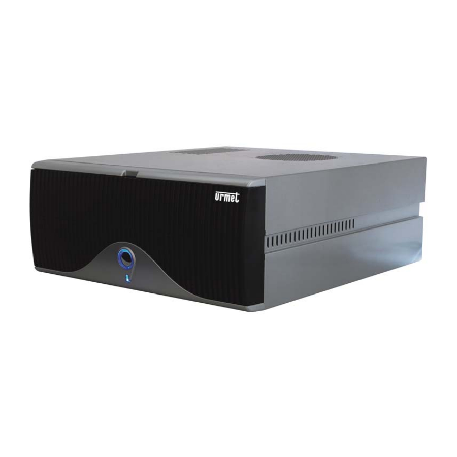
DESCRIPTION OF PARTS AND INSTALLATION FRONTAL VIEW PART DESCRIPTION ON/OFF BUTTON: Use this button to switch the VPR on and off safely (see chapter 3 in this manual). The light shows that the device is powered and on. POWER LED: This shows that the hard disk is in use. REAR VIEW PART DESCRIPTION... - Page 7 LAN - RJ45 network socket: Connect the UTP CAT5 standard LAN cable leading from a network device (e.g. switch or router). Connecting to the LAN/WAN is only needed to connect the device to a remote PC. Refer to chapter 4 of this manual for how to connect the VPR.
-
Page 8: How To Switch The Vpr On And Off
HOW TO SWITCH THE VPR ON AND OFF The VPR can automatically start up again after a sudden power blackout and normal system operation is restored. However, to avoid hard disk failures and damage to the system file, use the procedures for switching the device on and off safely shown below in normal conditions. -
Page 9: Use And Remote Connections
USE AND REMOTE CONNECTIONS The 1093/100 VPR may be used either locally (as a standalone device) and/or from remote locations connected via LAN and WAN, or via an analogue PSTN telephone line. Select the most suitable method of use according to your needs. IMPORTANT NOTE The VPR must be able to connect to the Internet in the event of an alarm to use the SMS test message or e-mail warning service. -
Page 10: Vpr Remote Connection Procedure Via Web Browser
To connect the VPR to the LAN (Figure 2), connect a normal network cable (UTP cat-5) from a network device to the RJ45 plug of the VPR. Figure 2: LAN connection 4.2.1 VPR REMOTE CONNECTION PROCEDURE VIA WEB BROWSER Switch the VPR on following the procedure shown in chapter 3.1 of this manual. On the remote PC, open a web browser and enter the IP address assigned to the VPR in the URL field (the default IP address is 192.168.1.111). -
Page 11: Connection To The Internet Via Adsl Broadband Router Ref. 1093/108 (Optional)
4.3.2 CONNECTION TO THE INTERNET VIA ADSL BROADBAND ROUTER REF. 1093/108 (OPTIONAL) This connection method may be used with a broadband connection, such as an ADSL line, either flat or charged by time. In this case, configure the VPR as belonging to the LAN to which the broadband router is connected and the private IP address of the router as gateway. -
Page 12: How To Install Vpr Mobile
4.4.1 HOW TO INSTALL VPR MOBILE Connect to the Internet via your mobile phone on the GPRS/EDGE/UMTS network and go to the following web address to download and install URMET VPR Mobile software: http://www.videosorv.com/vpr.wml Select “Download” on the web page and proceed with the installation procedure confirming all installation prompts that appear and selecting the memory where to save the application when required. -
Page 13: Wake-Up Function Via Dtmf Tone-Dial Telephone
WAKE-UP FUNCTION VIA DTMF TONE-DIAL TELEPHONE The VPR wake-up function for setting simply commands to the device is available when the VPR is not connected to the Internet using the optional PSTN analogue modem ref. 1093/107 via a normal DTMF tone-dial telephone. Three command types can be sent to the VPR via the telephone: connect to the Internet now, alarm warning on, alarm warning off. -
Page 14: Vpr Configuration
VPR CONFIGURATION The VPR needs to be appropriately configured by changing the standard parameters assigned by the manufacturer according to needs and to the specific range of use. When the VPR is on and during normal operation, select “SETTINGS” on the main navigation menu (top of the screen) with the mouse. -
Page 15: Cameras
CAMERAS Each connected camera may be configured independently so as to perform different functions according to the place of installation and the framed scene. IMPORTANT NOTE After completing all configurations on the page, press SAVE on the bottom of the page to save the changes. Otherwise, all changes will be ignored. -
Page 16: Recording Parameters
DOMES PTZ cameras controllable via RS-485 serial line and Pelco-D protocol (such as for example Easy Dome Urmet Domus ref. 1090/072 and 1090/082) can be controlled by the VPR. Connect the camera correctly as shown in chapter 8.1 and configure the following parameters: Select “USB”... -
Page 17: Alarms
ALARMS In the event of an alarm, the VPR will automatically establish the Internet connection to send a warning to up to three configurable e-mail addresses. The device will send a picture of what happened in the alarmed site along with its public IP address so as to connect to the VPR from a remote PC. -
Page 18: I/O Board (Optional)
I/O BOARD (OPTIONAL) This area is used to configure the optional GPIO board ref. 1093/105 for managing input sensors and output relays. This configuration area can only be accessed if the GPIO board is actually installed in the VPR. 5.4.1 MANUAL OUTPUT CONTROL Click on “Manual output control”... - Page 19 Reproduce the variations made using the GPIO board dip switch for each of the 8 outputs exactly: select “Input” if you have switched the corresponding output into a sensor input (dip switch on) or “Output” if you did not switch the output into a sensor input (dip switch position off).
-
Page 20: Upgrades
Output relay timing configuration procedure: Active: indicates the number of times to perform the relay closing command Every: indicates the interval of time between commands (relay closing) Total duration: indicates the relay closing application time. At the end of the connected sensor and relay configuration procedure, press SAVE to save the changes made. UPGRADES The VPR software can be upgraded directly via the Internet. -
Page 21: System
SYSTEM Access this configuration area to set the connection parameters and other important system settings. Administration privileges are required to edit system settings (see chapter 5.7). Enter a descriptive name of the VPR. 5.6.1 PROVIDER DATA The provider data are necessary to connect to the Internet via an analogue PSTN or ISDN serial modem, e.g. an optional PSTN modem 1093/107. - Page 22 Indicate the connection type to be used for Internet access: select “internet provider settings” if the VPR is connected to the Internet via an analogue modem PSTN (or ISDN) connected to the RS232 serial port (e.g. optional PSTN modem ref. 1093/107).
- Page 23 Motion areas for live camera video shown on the monitor can be defined by drawing a rectangle around the areas concerned by motion. Select “on” to show the rectangle or “off” to not show it. IMPORTANT NOTE Recordings always contain motion detection areas also if motion drawing function is off for live video. The VPR may generate a sound on a remote PC whenever motion is detected in the video of one of the four cameras shown on the monitor.
-
Page 24: Users
USERS The VPR allows to register different users with different authentication levels. The functions for which each registered user is authorised can be defined. The available user levels are: 1 - LIVE: the user is only authorised to view live camera video. 2 - RECORDINGS: the user is authorised to view live video, start/stop manual recordings, play recordings in the playback area and back recordings up. -
Page 25: Date
DATE Setting the date and time of the VPR is of fundamental importance for storing recordings. To change the date and time, select day, month, year, hours, minutes and press edit. The set date and time will appear on the top next to the “Current date” item. SAVE SETTING For higher safety, all VPR settings can be saved on a USB memory stick to create a sort of “emergency disk”. -
Page 26: 5.10 Management
5.10 MANAGEMENT The management area contains different management tools for editing VPR hardware settings, for testing alarms and for VPR connectivity, as well as the commands needed to start and stop the system. 5.10.1 EDITING HARDWARE SETTINGS The hardware settings page must be used very carefully and only when optional accessories are added or removed from the system (DVD burner ref. -
Page 27: Sending A Test Alarm
To add an optional GPIO board ref. 1093/105, install the board following the procedure described in chapter 8.2, then select “enable GPIO” on this page. Wait for a few seconds to allow the VPR to load the drivers: red indication “on” will appear instead of off to indicate that the GPIO board is correctly installed in the system. -
Page 28: Rebooting And Shutting Down
5.10.4 REBOOTING AND SHUTTING DOWN The VPR can be switched off and rebooted at any time. These commands can also be sent when connecting to the VPR from a remote location. The switch-off procedure can be performed following the procedure shown by pressing the on/off button on the front of the VPR itself (see chapter 4.1 of this manual). -
Page 29: How To Add Regions
5.11.1 HOW TO ADD REGIONS To add a rectangle, press “Add” and then draw a box on the area to be ignored with the mouse: position the mouse on the picture in the top left corner of the rectangle to be drawn, then click and drag to draw the area where to ignore motion and release the mouse button. -
Page 30: Using The Vpr
USING THE VPR The VPR will be ready to start normal work after installation and system configuration: all automatic features will be immediately operational. The VPR will be ready to work after initialising as shown in chapter 3.1. The video of all connected cameras will appear on the local monitor (if fitted) and the device will reply to connections from a remote PC (refer to chapter 4 in this manual for how to connect the VPR to a remote PC). -
Page 31: Quad Format
6.1.1 QUAD FORMAT All four video channels will appear on the monitor. To display in QUAD format, press the four-box button in the middle of the VIEW panel. When one video channel is shown full-screen, you can go back to QUAD mode simply by clicking directly over the picture shown. -
Page 32: Ptz Commands
PTZ COMMANDS In LIVE mode, the right panel on the monitor contains the commands needed to control PTZ cameras connected to the VPR (PTZ control panel). PTZ CONTROLS Select the camera to be controlled. Select the movement speed of the camera: shift the cursor leftwards to decrease the camera speed and rightwards to increase the speed. -
Page 33: How To Search For Recordings On The Hard Disk
HOW TO SEARCH FOR RECORDINGS ON THE HARD DISK Select PLAYBACK in the main navigation window to access the VPR hard disk search functions. The following window will appear containing the list of the last 20 recordings made on each video channel and the tools for searching for all other recordings on the hard disk. -
Page 34: How To Search For Recordings By Time
6.4.2 HOW TO SEARCH FOR RECORDINGS BY TIME Select the start and end time in the HOUR field to display the list of recordings made on a certain day from one time to another. Select the FROM hour and minutes and the TO hour and minutes in the HOUR box and press SEARCH to start searching. -
Page 35: Local Monitor Playback
6.5.1 LOCAL MONITOR PLAYBACK The controls for interacting with the recording being played will appear on the local monitor: |<<: Go back to beginning of recording STOP: stops playback PAUSE: pause playback PLAY: start playback Playing speed cursor: shift to adjust the playback speed (fast or slow motion). To go back to the recording list, close the recording window and press “X”... -
Page 36: How To Delete And Backup Recordings
HOW TO DELETE AND BACKUP RECORDINGS Several recordings can be selected in the recordings list (or search hit list) at the same time for deletion or backing up. 6.6.1 HOW TO DELETE A RECORDING To delete a recording, select the recording to be deleted and click on the selection field next to the name on the list. -
Page 37: How To Play Backup Copies
6.6.3 HOW TO PLAY BACKUP COPIES All recordings are converted to multimedia standard (*.mpg) and therefore may be played using a standard multimedia player (such as Windows Media Player or DivX player or VLC Media Player). To play a backup recording, browse the folders on your PC to locate the recording file to be played and double-click on it. The multimedia player of your PC (where applicable) will start automatically to play the selected file. -
Page 38: Vpr Technical Specifications
VPR TECHNICAL SPECIFICATIONS Item Specifications Product type Digital video recorder on dedicated PC platform Operating system LINUX Compression algorithm MPEG-4 PAL (compatible with black and white cameras) Video standard H 15625 Hz / V 50 Hz Image acquisition resolution 640x480 - 320x240 pixels Recording resolution 640x480 - 320x240 pixels Max →... -
Page 39: Optional Accessory Installation Procedures
OPTIONAL ACCESSORY INSTALLATION PROCEDURES USB/RS-485 CONVERTER REF. 1093/106 INSTALLATION PROCEDURE (OPTIONAL) The USB/RS-485 converter ref. 1093/106 must be connected to the VPR to control PTZ cameras. Connect the RX- wire of the RS-485 line from the camera to pin 5 of the RS-485 connector from the converter (corresponding to the red wire of the converter). -
Page 40: Sensor Input And Relay Output Configuration Procedure
Loosen the fastening screw and light the board support frame. Then remove the bracket covering a free slot. Insert the GPIO board making sure that it is correctly inserted in the guide on the bottom of the VPR in a free slot. Close the board support frame again and make sure that all boards are vertical and fixed. -
Page 41: Input Sensor And Output Relay Connection
INPUT SENSOR AND OUTPUT RELAY CONNECTION 25 PIN CONNECTOR Description Input sensor 1 Input sensor 2 Input sensor 3 Input sensor 4 Input sensor 5 Input sensor 6 Input sensor 7 Input sensor 8 Output 1 Output 2 Output 3 Output 4 Output 5 Output 6... - Page 42 Loosen the three screws fastening the cover and push the cover backwards to remove it. Open the front panel flap, then slightly press outwards to remove the plastic cover at the DVD burner housing. Insert the DVD burner in the housing making sure that the direction is correct (as shown in the figure). Stop when the frame is in line with the front panel of the burner.
- Page 43 Insert the other end of the IDE cable into the specific socket on the back of the burner (red wire on the power connector side). Free a spare power wire from power wire bundle of the VPR and connect it to the burner socket (yellow wire facing inwards).
- Page 44 DS1093-0002 LBT8018 PLANT BRANCHES URMET DOMUS S.p.A. 20151 MILANO – V. Gallarate 218 10154 TORINO (ITALY) Tel. 02.380.111.75 - Fax 02.380.111.80 VIA BOLOGNA 188/C 00043 CIAMPINO (ROMA) V. L.Einaudi 17/19A Tel. 011.24.00.000 (automatic) Tel. 06.791.07.30 - Fax 06.791.48.97 011.24.00.300 - 323 80013 CASALNUOVO (NA) V.
Need help?
Do you have a question about the 1093/004AHD and is the answer not in the manual?
Questions and answers