
Related Manuals for Allied Vision PROSILICA GC


Summary of Contents for Allied Vision PROSILICA GC
- Page 1 GigE V ISION AMERAS Prosilica GC Technical Manual V2.2.0 Allied Vision Technologies GmbH // Taschenweg 2a, D-07646 Stadtroda / Germany 2016-July-04...
-
Page 2: Prosilica Gc At A Glance
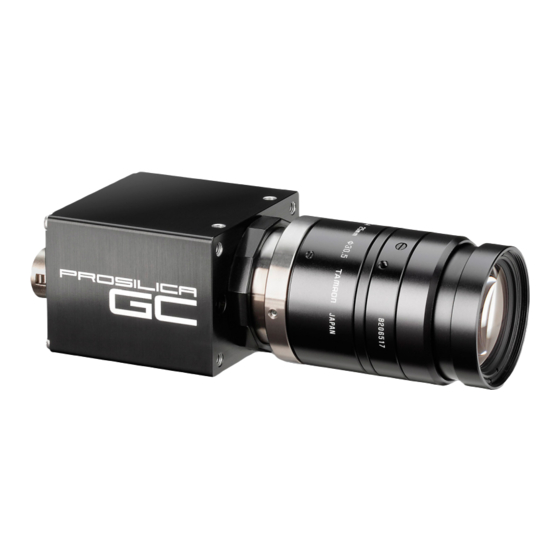
Prosilica GC at a glance Prosilica GC at a glance Prosilica GC cameras have a Gigabit Ethernet (GigE) interface and work with GigE hardware and cable lengths up to 100 m. Prosilica GC cameras are GigE Vision V1.2 and GenICam V1.2.1 compliant. Applied standards GigE Vision®... -
Page 3: Contact Us
Contact us Contact us Connect with Allied Vision by function https://www.alliedvision.com/en/meta-header/contact.html Find an Allied Vision office or distribution partner https://www.alliedvision.com/en/about-us/where-we-are.html Email info@alliedvision.com support@alliedvision.com Sales offices Europe, Middle East, and Africa: +49 36428-677-230 North and South America: +1 (877) USA-1394 Asia-Pacific: +65 6634-9027... -
Page 4: Table Of Contents
Contents Prosilica GC at a glance Applied standards ............... . . 2 What else do you need? . - Page 5 Prosilica GC model frame rate comparison........
- Page 6 Absolute QE............... . . 113 Prosilica GC Technical Manual V2.2.0...
- Page 7 Prosilica GC CMOS model housing (C-Mount) ........
-
Page 8: Document History And Conventions
Document history and conventions This chapter includes: • Document history • Layout styles and symbols used in this manual Prosilica GC Technical Manual V2.2.0... -
Page 9: Document History
Updated the exposure control values in the Specifications chapter Added Vimba SDK link in the Additional references section Updated Allied Vision recommended cabling to Category 6 or higher in the Gigabit Ethernet interface section V2.0.6 2013-Jul-05 Added contact information for Allied Vision Technologies (Shanghai) Co. Ltd. - Page 10 GC1380H, GC1380CH, GC1600H, GC1600CH, GC2450, GC2450C Added Installation chapter Removed image flow chapter and added the diagrams to the Appendix Added new image flow diagram for new Prosilica GC hardware revision D models at the end of the Specifications chapter Updated frame rate information...
-
Page 11: Manual Conventions
You have to follow these instructions to avoid malfunctions. Practical hint This symbol highlights a practical hint that helps to better understand the camera‘s features and functions, and to make better use of it. Prosilica GC Technical Manual V2.2.0... - Page 12 Document history and conventions Further information available online This symbol highlights URLs for further information. The URL itself is shown in blue. Example: https://www.alliedvision.com Prosilica GC Technical Manual V2.2.0...
-
Page 13: Safety And Regulations
Safety and regulations § This chapter includes: • General cautions and warnings for Prosilica GC cameras • Information about the legal requirements and restrictions for Prosilica GC cameras based on current and relevant regulations • Particular emphasis has been given to regulations... -
Page 14: General Cautions And Warnings
This product can be damaged by some volatile cleaning agents. Avoid cleaning the image sensor unless absolutely necessary. See instructions on optics cleaning in this document. Allied Vision can clean your camera as a service for you, if necessary. For more information, contact Allied Vision support. -
Page 15: Regulations
European Economic Area requirements CE and RoHS Allied Vision Technologies declares under its sole responsibility that all standard cameras of the Prosilica GC family to which this declaration relates are in conformity with the following standard(s) or other normative document(s): •... -
Page 16: Industry Canada Equipment Standard For Digital Equipment (Ices)
Other legal notices Trademarks Unless stated otherwise, all trademarks shown in this document of Allied Vision Technologies are brands protected by law. All other product or company names may be trademarks of their respective owners. Warranty The information provided by Allied Vision Technologies is supplied without any guarantees or warranty whatsoever, be it specific or implicit. -
Page 17: Copyright
It is not permitted to copy or modify them for trade use or transfer, nor may they be used on websites. For the latest version of this document, visit the Allied Vision documentation website. Copyright © 2016 Allied Vision Technologies GmbH. All rights reserved. -
Page 18: Installation And Hardware
Installation and hardware This chapter describes the components required for your vision system including configuring the host computer, Ethernet adapter settings, and connecting your Prosilica GC camera. Prosilica GC Technical Manual V2.2.0... -
Page 19: Configuring The Host Computer
Installation and hardware Configuring the host computer Allied Vision GigE Vision cameras can operate on 10/100 or Gigabit speed Ethernet adapters. In order to reach the maximum camera frame rate, a Gigabit speed Ethernet adapter with jumbo packet support is required. -
Page 20: Ethernet Adapter Driver Settings
Transmit Buffers 256 bytes Default packet size The default packet size of Allied Vision GigE cameras is 8228 bytes. The host network adapter needs to support a packet size of equal or larger size to stream from the camera. Ethernet adapter For desktop systems, use a PCI Express bus Ethernet adapter. -
Page 21: Enabling Jumbo Packets
Contact your Allied Vision Sales representative or your local Allied Vision distribution partner for information on accessories and lens recommendations: https://www.alliedvision.com/en/about-us/where-we-are.html Downloading camera drivers Allied Vision GigE cameras work with any or all of the following software options. Vimba Viewer or Vimba SDK: https://www.alliedvision.com/en/products/software Third-party software solutions: https://www.alliedvision.com/en/products/software/third-party-libraries.html... -
Page 22: Powering Up The Camera
Installation and hardware Powering up the camera A camera power adapter for each GigE camera is available from Allied Vision. See Specifications on page 23 for connector definition and voltage specifications. For Prosilica GC cameras • Use only DC power supplies with insulated cases. -
Page 23: Specifications
• Technical specifications • Absolute quantum efficiency plots • Spectral response plots • ROI height vs. frame rate plots • Camera feature comparison for hardware version D models (serial number 02-21XXD-XXXXX) • Image data flow diagram Prosilica GC Technical Manual V2.2.0... -
Page 24: Notes On Specifications
Appendix on page 81. Hardware version incompatibility Prosilica GC hardware version D models and firmware are not compatible with Pro- silica GC hardware version A models. Monochrome models As monochrome models do not have an optical filter always attach a dust cap when a lens is not attached to minimize the possibility of contaminants falling on the sensor surface. -
Page 25: Resolution And Roi Frame Rate
Absolute QE plots for OnSemi CCD sensors The curves in the absolute QE plots shown in this chapter are from the sensor manufacturer data sheet. The information was correct at the time of publishing. Sensor specifications may change without notice. Prosilica GC Technical Manual V2.2.0... -
Page 26: Spectral Response Plots
QE values (@ 448 nm, 529 nm, 632 nm) for color sensors and one measured QE value (@ 529 nm) for monochrome sensors. Prosilica GC Technical Manual V2.2.0... -
Page 27: Prosilica Gc660, Gc660C
10 ns for non-isolated I/O; 1.3 µs for isolated I/O Operating temperature 0 °C to +50 °C ambient temperature (without condensation) Storage temperature -10 °C to +70 °C ambient temperature (without condensation) Table 2: Prosilica GC660, GC660C model specifications Prosilica GC Technical Manual V2.2.0... - Page 28 It was changed to 658 pixels so that the color version would image with Vimba when using default values. Modular Concept. For more information on available optical filters see the Table 2: Prosilica GC660, GC660C model specifications (continued) Prosilica GC Technical Manual V2.2.0...
-
Page 29: Absolute Qe
Figure 1: Prosilica GC660, GC660C (Sony ICX618) absolute QE Spectral response Red Response Green Response Blue Response Monochrome QE 0.4000 Sony ICX618 spectral response 0.3000 0.2000 0.1000 0.0000 1000 Wavelength [nm] Figure 2: Prosilica GC660, GC660C (Sony ICX618) spectral response Prosilica GC Technical Manual V2.2.0... -
Page 30: Roi Frame Rate
Figure 3: Frame rate as a function of ROI height plot Height [pixels] Frame rate [fps] Height [pixels] Frame rate [fps] 121.18 226.23 130.23 265.35 142.31 320.82 156.86 405.61 174.32 482.06 197.16 514.37 Table 3: Frame rate as a function of ROI height table Prosilica GC Technical Manual V2.2.0... -
Page 31: Prosilica Gc1290, Gc1290C
10 ns for non-isolated I/O; 1.3 μs for isolated I/O Operating temperature 0 °C to +50 °C ambient temperature (without condensation) Storage temperature -10 °C to +70 °C ambient temperature (without condensation) Table 4: Prosilica GC1290, GC1290C model specifications Prosilica GC Technical Manual V2.2.0... - Page 32 CE, RoHS, REACH, WEEE, FCC, ICES Temperature monitoring Available for main board only. Resolution: 0.031; Accuracy: ± 1 °C Modular Concept. For more information on available optical filters see the Table 4: Prosilica GC1290, GC1290C model specifications (continued) Prosilica GC Technical Manual V2.2.0...
-
Page 33: Absolute Qe
Figure 4: Prosilica GC1290, GC1290C (Sony ICX445) absolute QE Spectral response Red Response Green Response Blue Response Monochrome Response 0.3000 Sony ICX445 spectral response 0.2000 0.1000 0.0000 1000 Wavelength [nm] Figure 5: Prosilica GC1290, GC1290C (Sony ICX445) spectral response Prosilica GC Technical Manual V2.2.0... -
Page 34: Roi Frame Rate
Height [pixels] Frame rate [fps] Height [pixels] Frame rate [fps] 33.31 87.96 35.30 117.07 39.21 174.96 44.10 232.41 50.38 289.45 58.75 315.23 70.45 339.43 Table 5: Frame rate as a function of ROI height table Prosilica GC Technical Manual V2.2.0... -
Page 35: Prosilica Gc1380H, Gc1380Ch
10 ns for non-isolated I/O; 1.3 μs for isolated I/O Operating temperature 0 °C to +50 °C ambient temperature (without condensation) Storage temperature -10 °C to +70 °C ambient temperature (without condensation) Table 6: Prosilica GC1380H, GC1380CH model specifications Prosilica GC Technical Manual V2.2.0... - Page 36 CE, RoHS, REACH, WEEE, FCC, ICES Temperature monitoring Available for main board only. Resolution: 0.031; Accuracy: ± 1 °C Modular Concept. For more information on available optical filters see the Table 6: Prosilica GC1380H, GC1380CH model specifications (continued) Prosilica GC Technical Manual V2.2.0...
-
Page 37: Absolute Qe
Figure 7: Prosilica GC1380H, GC1380CH (Sony ICX285) absolute QE Spectral response Red Response Green Response Blue Response Monochrome Response 0.3000 Sony ICX285 spectral response 0.2000 0.1000 0.0000 1000 Wavelength [nm] Figure 8: Prosilica GC1380H, GC1380CH (Sony ICX285) spectral response Prosilica GC Technical Manual V2.2.0... -
Page 38: Roi Frame Rate
Frame rate [fps] Height [pixels] Frame rate [fps] 1024 30.48 76.89 1000 31.1 97.36 132.68 37.48 162.08 41.76 186.93 47.15 197.01 54.13 205.88 63.53 Table 7: Frame rate as a function of ROI height table Prosilica GC Technical Manual V2.2.0... -
Page 39: Prosilica Gc1600H, Gc1600Ch
20 ns for non-isolated I/O; 0.5 μs for isolated I/O Operating temperature 0 °C to +50 °C ambient temperature (without condensation) Storage temperature -10 °C to +70 °C ambient temperature (without condensation) Table 8: Prosilica GC1600H, GC1600CH model specifications Prosilica GC Technical Manual V2.2.0... - Page 40 CE, RoHS, REACH, WEEE, FCC, ICES Temperature monitoring Available for main board only. Resolution: 0.031; Accuracy: ± 1 °C Modular Concept. For more information on available optical filters see the Table 8: Prosilica GC1600H, GC1600CH model specifications (continued) Prosilica GC Technical Manual V2.2.0...
-
Page 41: Absolute Qe
Figure 10: Prosilica GC1600H, GC1600CH (Sony ICX274) absolute QE Spectral response Red Response Green Response Blue Response Monochrome Response 0.3000 Sony ICX274 spectral response 0.2000 0.1000 0.0000 1000 Wavelength [nm] Figure 11: Prosilica GC1600H, GC1600CH (Sony ICX274) spectral response Prosilica GC Technical Manual V2.2.0... -
Page 42: Roi Frame Rate
Height [pixels] Frame rate [fps] 1220 25.82 67.72 1100 28.39 84.42 1000 30.96 112.06 34.04 166.62 37.8 220.22 42.49 272.89 48.52 296.53 56.53 318.62 Table 9: Frame rate as a function of ROI height table Prosilica GC Technical Manual V2.2.0... -
Page 43: Prosilica Gc2450, Gc2450C
20 ns for non-isolated I/O; 1.3 μs for isolated I/O Operating temperature 0 °C to +40 °C ambient temperature (without condensation) Storage temperature -10 °C to +70 °C ambient temperature (without condensation) Table 10: Prosilica GC2450, GC2450C model specifications Prosilica GC Technical Manual V2.2.0... - Page 44 CE, RoHS, REACH, WEEE, FCC, ICES Temperature monitoring Available for main board only. Resolution: 0.031; Accuracy: ± 1 °C Modular Concept. For more information on available optical filters see the Table 10: Prosilica GC2450, GC2450C model specifications (continued) Prosilica GC Technical Manual V2.2.0...
-
Page 45: Absolute Qe
Figure 13: Prosilica GC2450/GC2450C (Sony ICX625) absolute QE Spectral response Red Response Green Response Blue Response Monochrome Response 0.3000 Sony ICX625 spectral response 0.2000 0.1000 0.0000 1000 Wavelength [nm] Figure 14: Prosilica GC2450/GC2450C (Sony ICX625) absolute QE Prosilica GC Technical Manual V2.2.0... -
Page 46: Roi Frame Rate
Frame rate [fps] 2050 15.11 35.84 2000 15.42 44.21 1800 16.79 57.66 1600 18.42 1400 20.4 74.7 1200 22.87 79.4 1000 26.01 81.1 30.14 82.51 Table 11: Frame rate as a function of ROI height table Prosilica GC Technical Manual V2.2.0... -
Page 47: Prosilica Gc Model Frame Rate Comparison
Specifications Prosilica GC model frame rate comparison Prosilica GC model comparison GC2450 GC1660 GC1380 GC1290 GC660 1000 1250 1500 1750 2000 2250 Height [pixels] Figure 16: Maximum frame rate comparison for select models Prosilica GC model comparison Sensor Sensor Frame... -
Page 48: Camera Feature Highlights
Camera feature highlights Allied Vision cameras support a number of standard and extended features. The table below identifies a selection of capabilities of the Prosilica GC camera family. A complete listing of camera features, including feature definitions can be found on the Allied Vision documentation website: •... -
Page 49: Camera Feature Comparison
Specifications Camera feature comparison Allied Vision cameras support a number of standard and extended features. The table below identifies a selection of capabilities and compares the availability of features in Prosilica GC camera models. A complete listing of camera features, including feature definitions can be found on the Allied Vision documentation website: •... -
Page 50: Image Data Flow
The number of bits per pixel varies depending on the pixel format selected. The output from frame memory to the GigE interface is dependent on the pixel format GigE Interface selected. GigE Host Figure 18: Image flow diagram for Prosilica GC (hardware version D) models Prosilica GC Technical Manual V2.2.0... -
Page 51: Mechanical Dimensions
Mechanical dimensions This chapter includes: • CAD drawings and dimensions of standard housing models • Sensor position accuracy • Maximum protrusion distance and filter diameter for C-Mount and CS-Mount Prosilica GC Technical Manual V2.2.0... -
Page 52: Prosilica Gc Ccd Model Housing (C-Mount)
Mechanical dimensions The Prosilica GC family offers both CCD and CMOS sensor models. CCD cameras utilize additional circuitry required for A/D conversion. As a result, CMOS models offer a shorter mechanical package than CCD models. Prosilica GC cameras are available with different lens mount options. For more information, see the Modular Concept document at: https://www.alliedvision.com/en/support/technical-documentation.html... -
Page 53: Tripod Adapter
Mechanical dimensions Tripod adapter A Prosilica GC camera can be mounted on a camera tripod by using a mounting plate. The same tripod adapter can be used for all models within the Prosilica GC camera family. Prosilica GC tripod adapter... -
Page 54: Adjustment Of C-Mount
When the locking ring is loose, unthread the ring a few turns from the camera face. Locking wrench Contact the Allied Vision Sales team or your local Allied Vision distribution partner to purchase the hexagonal lens adjustment wrench for Prosilica GC cameras with C/CS locking ring (Allied Vision order code 02-5003A). -
Page 55: Lens Protrusion For C-Mount Cameras
Lens protrusion Front Plate holder Sec on A-A for C-Mount Sec on A-A for C-Mount monochrome cameras color cameras Figure 22: Cross section of typical Prosilica GC assembly with C-Mount Model Lens protrusion [mm] Model Lens protrusion [mm] GC660 13.64 GC1380CH 8.31... -
Page 56: Sensor Position Accuracy
±400 µm (sensor shift) ±10 µm (optical back focal distance) α ± 1° (sensor rotation) Alignment Optical alignment of photo sensitive sensor area into camera front module (lens mount front flange). Table 15: Sensor position accuracy criteria Prosilica GC Technical Manual V2.2.0... -
Page 57: Ir Cut Filter
Mechanical dimensions IR cut filter All Prosilica GC color models are equipped with an infrared block filter (IR cut filter). This filter is employed to prevent infrared light from passing to the sensor. In the absence of an IR filter, images are dominated by red and incapable of being properly color balanced. -
Page 58: Camera Interfaces
This chapter includes: • A general description of the inputs and outputs (including trigger features) • I/O connector pin assignments • I/O block diagrams • A general description of trigger rules such as timing diagram and definitions Prosilica GC Technical Manual V2.2.0... -
Page 59: Back Panel
This section provides information on Gigabit Ethernet interface, inputs and outputs, and trigger features. Accessories Contact your Allied Vision Sales representative or your local Allied Vision distribution partner for information on accessories, go to: https://www.alliedvision.com/en/about-us/where-we-are.html Figure 25: Prosilica GC port, interface, LEDs... -
Page 60: Status Leds
The GigE Installation Manual offers detailed instructions for using Prosilica GC cameras. https://www.alliedvision.com/en/support/technical-documentation/prosilica-gc- documentation.html Ethernet adapters See the Hardware Selection for Allied Vision GigE Cameras application note for a list of recommended Ethernet adapters: https://www.alliedvision.com/en/support/technical-papers-knowledge- base.html A standard Ethernet adapter is available for purchase from Allied Vision:... -
Page 61: Camera I/O Connector Pin Assignment
Cable lengths up to 100 m are supported. The 8-pin RJ45 jack has the pin assignment according to the Ethernet standard (IEEE 802.3 1000BASE-T). Allied Vision recommends using locking-screw cables from Components Express, Inc. for a perfect fit. Visit the CEI product configurator to customize the cable according to your needs. -
Page 62: I/O Definition
I/O definition Camera power The Prosilica GC camera family has recently been updated to offer an expanded input power voltage range. The camera serial number is used to differentiate between cameras that offer 5 to 16 VDC and those that offer 5 to 25 VDC. -
Page 63: Rxd Rs232 And Txd Rs232
Trigger Input A relay of the trigger input signal used to “daisy chain” the trigger signal for multiple cameras. Readout Valid when camera is reading out data. Imaging Valid when camera is exposing or reading out. Prosilica GC Technical Manual V2.2.0... -
Page 64: Signal Ground
These signals are reserved for future use and should be left disconnected. Video iris output Prosilica GC cameras provide built-in auto iris controls for controlling video-type auto-iris lenses. These lenses are available from many popular security lens companies including Pentax, Fujinon, Tamron, Schneider, etc. - Page 65 Camera interfaces CABLE SIDE CAMERA GND CAMERA GND 12 V POWER CAMERA POWER HIROSE HR10A-10P-12S LENS POWER VIDEO SIGNAL LENS GROUND JEITA CONNECTOR Figure 26: Prosilica GC video iris schematic Prosilica GC Technical Manual V2.2.0...
-
Page 66: Camera Trigger
2.7 K 24 V 1.8 K 4.7 K Figure 27: Prosilica GC opto-isolated user circuit *Cameras with SN: 02-XXXXX-0XXXX, R1 necessary for input greater than 5 V. Cameras with SN: 02-XXXXX-1XXXX, no R1 necessary, 5 to 24 V. Input/Output Input: Incoming trigger must be able to source 10 mA. -
Page 67: Camera I/O Non-Isolated User Circuit Example
OUT 2 OUT 2 (3.3 V RECEIVER) HIROSE HR10A-10P-12S Figure 28: Prosilica GC non-isolated user circuit Input/Output Input: Incoming trigger must be able to source 10 µA, at 3.3 V. Input trigger voltage greater than 5.5 V will damage the camera. -
Page 68: Trigger Timing Diagram
Exposure length of exposure. N+ 1 Trigger ji er Readout N+ 1 Interline me Trigger ready Imaging Idle Figure 29: Prosilica GC internal signal timing waveform Prosilica GC Technical Manual V2.2.0... -
Page 69: Notes On Triggering
The end of exposure will always trigger the next readout. • The end of exposure must always end after the current readout. • The start of exposure must always correspond with the interline time if readout is true. Prosilica GC Technical Manual V2.2.0... - Page 70 Trigger Jitter can be up to 1 row time since Exposure must always begin on an Interline boundary. For a more detailed description of the trigger concept for advanced users and special scenarios, see the Triggering Concept application note: https://www.alliedvision.com/en/support/technical-papers-knowledge- base.html Prosilica GC Technical Manual V2.2.0...
-
Page 71: Cleaning Optical Components
Cleaning optical components This chapter describes safety instructions and cautions for cleaning lenses, optical filters, protection glass, or sensors. Prosilica GC Technical Manual V2.2.0... -
Page 72: Warranty
Important instructions to be read first Read these instructions before you contact Allied Vision or your Allied Vision distribution partner for assistance. Contact Allied Vision or your Allied Vision distribution partner if you are not familiar with the procedures described below. Warranty... -
Page 73: Identifying Impurities
Cleaning optical components Identifying impurities If you observe any image artifacts in your video preview of your Prosilica GC camera you may have impurities either on the lens, filter/protection glass, or on the sensor protection glass. Every Prosilica GC camera is cleaned prior to sealing and shipment;... -
Page 74: Materials For Cleaning Optical Components
Unplug the camera from any power supply before cleaning. Apply a small amount of cleaning liquid to a new lens cleaning cotton, cloth, or tissue. The cotton, cloth, or lens tissue should be moist, but not dripping. Prosilica GC Technical Manual V2.2.0... -
Page 75: Cleaning With Compressed Air
Allied Vision distribution partner or Allied Vision support. Cleaning with compressed air Allied Vision does not recommend cleaning Prosilica GC cameras with compressed air. Possible material damage •... -
Page 76: Firmware Update
Firmware update This chapter includes instructions on updating the firmware on your Allied Vision Prosilica GC camera. Prosilica GC Technical Manual V2.2.0... - Page 77 Firmware update Download the latest GigE firmware loader from the Allied Vision website: https://www.alliedvision.com/en/support/firmware Saved camera user sets If new firmware contains a new feature/control, saved camera UserSets/ ConfigFiles will be invalidated and erased! Before loading new firmware, backup your current camera settings.
- Page 78 Select the Use recovery mode checkbox if the connected GigE camera is not found by the firmware loader, or if the GigE camera is listed as unavailable. When selected, power cycle the camera to enter the Boot Loader mode. Prosilica GC Technical Manual V2.2.0...
- Page 79 Click Upload to start the update. The existing firmware will be erased and the new firmware will be updated to the camera. Possible material damage Do not unplug the GigE cable or camera power supply during the update procedure. Prosilica GC Technical Manual V2.2.0...
- Page 80 Firmware update The Firmware Loader will display a success status upon completion. Click Quit to exit the loader. Prosilica GC Technical Manual V2.2.0...
-
Page 81: Appendix
Appendix The appendix includes the following information for older Prosilica GC cameras up to serial number 02- 21XXA (hardware version A): • Specification tables • Absolute quantum efficiency plots • ROI height vs. frame rate plots • Camera feature comparison of hardware version A models •... -
Page 82: Prosilica Gc650, Gc650C (02-2110A, 02-2111A)
3.3 W @ 12 VDC Trigger latency 1.0 µs for non-isolated I/O; 2.8 µs for isolated I/O Trigger jitter ±20 ns for non-isolated I/O; ±0.5 µs for isolated I/O Table 19: Prosilica GC650, GC650C model specifications Prosilica GC Technical Manual V2.2.0... - Page 83 GigE Vision® Standard V1.2 Camera control standard GenICam SFNC V1.2.1 Regulations CE, RoHS, REACH, WEEE, FCC, ICES For more information on available optical filters see the Modular Concept. Table 19: Prosilica GC650, GC650C model specifications (continued) Prosilica GC Technical Manual V2.2.0...
-
Page 84: Absolute Qe
Appendix Absolute QE 1000 l ngth [nm] Figure 31: Prosilica GC650 (Sony ICX424) absolute QE Green Blue l ngth [nm] Figure 32: Prosilica GC650C (Sony ICX424) absolute QE Prosilica GC Technical Manual V2.2.0... -
Page 85: Roi Frame Rate
Height [pixels] Frame rate [fps] Height [pixels] Frame rate [fps] 90.0 187.5 97.0 231.0 107.0 300.4 120.0 428.9 136.6 577.0 157.8 652.0 Table 20: Frame rate as a function of ROI height table [width=659 pixels] Prosilica GC Technical Manual V2.2.0... -
Page 86: Prosilica Gc655, Gc655C (02-2115A, 02-2116A)
3.0 W @ 12 VDC Trigger latency 1.0 µs for non-isolated I/O; 2.8 µs for isolated I/O Trigger jitter ±20 ns for non-isolated I/O; ±0.5 µs for isolated I/O Table 21: Prosilica GC655, GC655C model specifications Prosilica GC Technical Manual V2.2.0... -
Page 87: Absolute Qe
With protection glass or filters, quantum efficiency (QE) decreases by approximately 10%. The uncertainty in measurement of the QE is +/ 10.25%. The values are typical and are subject to minor variations. 1000 Wavelength [nm] Figure 34: Prosilica GC655, GC655C (Sony ICX414) absolute QE Prosilica GC Technical Manual V2.2.0... -
Page 88: Roi Frame Rate
Height [pixels] Frame rate [fps] Height [pixels] Frame rate [fps] 90.0 187.5 97.0 231.0 107.2 300.4 120.1 428.9 136.6 577.0 157.8 652.0 Table 22: Frame rate as a function of ROI height table [width=659 pixels] Prosilica GC Technical Manual V2.2.0... -
Page 89: Prosilica Gc660, Gc660C (02-2180A, 02-2181A)
1.0 µs for non-isolated I/O; 2.8 µs for isolated I/O Trigger jitter ±20 ns for non-isolated I/O; ±0.5 µs for isolated I/O Propagation delay (t 10 ns for non-isolated I/O; 1.3 µs for isolated I/O Table 23: Prosilica GC660, GC660C model specifications Prosilica GC Technical Manual V2.2.0... -
Page 90: Absolute Qe
With protection glass or filters, quantum efficiency (QE) decreases by approximately 10%. The uncertainty in measurement of the QE is +/ 10.25%. The values are typical and are subject to minor variations. 1000 Wavelength [nm] Figure 36: Prosilica GC660, GC660C (Sony ICX618) absolute QE Prosilica GC Technical Manual V2.2.0... -
Page 91: Roi Frame Rate
Figure 37: Frame rate as a function of ROI height plot Height [pixels] Frame rate [fps] Height [pixels] Frame rate [fps] 119.29 222.7 128.2 261.2 140.09 315.8 154.41 399.28 171.99 474.51 194.08 506.32 Table 24: Frame rate as a function of ROI height table Prosilica GC Technical Manual V2.2.0... -
Page 92: Prosilica Gc750, Gc750C (02-2160A, 02-2161A)
Operating temperature 0 °C to +50 °C ambient temperature (without condensation) Storage temperature -10 °C to +70 °C ambient temperature (without condensation) Operating humidity 20% to 80% non-condensing Table 25: Prosilica GC750, GC750C model specifications Prosilica GC Technical Manual V2.2.0... - Page 93 GigE Vision® Standard V1.2 Camera control standard GenICam SFNC V1.2.1 Regulations CE, RoHS, REACH, WEEE, FCC, ICES For more information on available optical filters see the Modular Concept. Table 25: Prosilica GC750, GC750C model specifications (continued) Prosilica GC Technical Manual V2.2.0...
-
Page 94: Absolute Qe
Appendix Absolute QE 1000 l ngth [nm] Figure 38: Prosilica GC750 (ON Semiconductor MT9V022) absolute QE Green Blue l ngth [nm] Figure 39: Prosilica GC750C (ON Semiconductor MT9V022) absolute QE Prosilica GC Technical Manual V2.2.0... -
Page 95: Roi Frame Rate
Figure 40: Frame rate as a function of ROI height plot [width=752 pixels] Height [pixels] Frame rate [fps] Height [pixels] Frame rate [fps] 62.9 238.0 75.3 371.7 97.6 560.6 114.5 674.9 138.4 806.4 175.1 Table 26: Frame rate as a function of ROI height table [width=752 pixels] Prosilica GC Technical Manual V2.2.0... -
Page 96: Prosilica Gc780, Gc780C (02-2117A, 02-2118A)
10 ns for non-isolated I/O; 1.3 μs for isolated I/O Operating temperature 0 °C to +50 °C ambient temperature (without condensation) Storage temperature -10 °C to +70 °C ambient temperature (without condensation) Table 27: Prosilica GC780, GC780C model specifications Prosilica GC Technical Manual V2.2.0... -
Page 97: Absolute Qe
With protection glass or filters, quantum efficiency (QE) decreases by approximately 10%. The uncertainty in measurement of the QE is +/ 10.25%. The values are typical and are subject to minor variations. 1000 Wavelength [nm] Figure 41: Prosilica GC780, GC780C (Sony ICX415) absolute QE Prosilica GC Technical Manual V2.2.0... -
Page 98: Roi Frame Rate
Figure 42: Frame rate as a function of ROI height plot [width=782 pixels] Height [pixels] Frame rate [fps] Height [pixels] Frame rate [fps] 63.9 201.1 73.4 268.1 89.8 402.6 115.2 573.8 134.5 668.6 161.5 Table 28: Frame rate as a function of ROI height table [width=782 pixels] Prosilica GC Technical Manual V2.2.0... -
Page 99: Prosilica Gc1020, Gc1020C (02-2165A, 02-2165B, 02-2166A, 02-2166B)
±20 ns for non-isolated I/O; ±0.5 µs for isolated I/O Propagation delay (t 10 ns for non-isolated I/O; 1.3 μs for isolated I/O Operating temperature 0 °C to +50 °C ambient temperature (without condensation) Table 29: Prosilica GC1020, GC1020C model specifications Prosilica GC Technical Manual V2.2.0... -
Page 100: Absolute Qe
With protection glass or filters, quantum efficiency (QE) decreases by approximately 10%. The uncertainty in measurement of the QE is +/ 10%. The values are typical and are subject to minor variations. 1000 Wavelength [nm] Figure 43: Prosilica GC1020, GC1020C (Sony ICX204) absolute QE Prosilica GC Technical Manual V2.2.0... -
Page 101: Roi Frame Rate
Height [pixels] Frame rate [fps] Height [pixels] Frame rate [fps] 33.4 92.4 36.2 134.5 41.3 173.0 47.0 210.3 57.0 226.3 70.5 241.0 Table 30: Frame rate as a function of ROI height table [width=1024 pixels] Prosilica GC Technical Manual V2.2.0... -
Page 102: Prosilica Gc1290, Gc1290C (02-2185A, 02-2186A)
2 µs for non-isolated I/O; 10 µs for isolated I/O Trigger jitter ±20 ns for non-isolated I/O; ±0.5 µs for isolated I/O Propagation delay (t 10 ns for non-isolated I/O; 1.3 μs for isolated I/O Table 31: Prosilica GC1290, GC1290C model specifications Prosilica GC Technical Manual V2.2.0... -
Page 103: Absolute Qe
With protection glass or filters, quantum efficiency (QE) decreases by approximately 10%. The uncertainty in measurement of the QE is +/ 10.25%. The values are typical and are subject to minor variations. 1000 Wavelength [nm] Figure 45: Prosilica GC1290, GC1290C (Sony ICX445) absolute QE Prosilica GC Technical Manual V2.2.0... -
Page 104: Roi Frame Rate
Height [pixels] Frame rate [fps] Height [pixels] Frame rate [fps] 32.79 86.59 34.75 115.24 38.6 172.22 43.41 228.78 49.6 284.93 57.83 310.31 69.35 334.13 Table 32: Frame rate as a function of ROI height table Prosilica GC Technical Manual V2.2.0... -
Page 105: Prosilica Gc1350, Gc1350C (02-2130A, 02-2131A)
±20 ns for non-isolated I/O; ±0.5 µs for isolated I/O Propagation delay (t 10 ns for non-isolated I/O; 1.3 μs for isolated I/O Operating temperature 0 °C to +50 °C ambient temperature (without condensation) Table 33: Prosilica GC1350, GC1350C model specifications Prosilica GC Technical Manual V2.2.0... - Page 106 GigE Vision Standard V1.2 Camera control standard GenICam SFNC V1.2.1 Regulations CE, RoHS, REACH, WEEE, FCC, ICES For more information on available optical filters see the Modular Concept. Table 33: Prosilica GC1350, GC1350C model specifications (continued) Prosilica GC Technical Manual V2.2.0...
-
Page 107: Absolute Qe
Appendix Absolute QE 1000 l ngth [nm] Figure 47: Prosilica GC1350 (Sony ICX205) absolute QE Green Blue l ngth [nm] Figure 48: Prosilica GC1350C (Sony ICX205) absolute QE Prosilica GC Technical Manual V2.2.0... -
Page 108: Roi Frame Rate
Height [pixels] Frame rate [fps] 1024 20.0 45.3 1000 20.4 54.8 22.1 69.4 24.2 80.1 26.8 88.2 29.7 91.3 33.6 93.9 38.5 Table 34: Frame rate as a function of ROI height table [width=1360 pixels] Prosilica GC Technical Manual V2.2.0... -
Page 109: Prosilica Gc1380, Gc1380C (02-2140A, 02-2141A)
±20 ns for non-isolated I/O; ±0.5 µs for isolated I/O Propagation delay (t 10 ns for non-isolated I/O; 1.3 μs for isolated I/O Operating temperature 0 °C to +50 °C ambient temperature (without condensation) Table 35: Prosilica GC1380, GC1380C model specifications Prosilica GC Technical Manual V2.2.0... -
Page 110: Absolute Qe
With protection glass or filters, quantum efficiency (QE) decreases by approximately 10%. The uncertainty in measurement of the QE is +/ 10.25%. The values are typical and are subject to minor variations. 1000 Wavelength [nm] Figure 50: Prosilica GC1380, GC1380C (Sony ICX285) absolute QE plot Prosilica GC Technical Manual V2.2.0... -
Page 111: Roi Frame Rate
Height [pixels] Frame rate [fps] 1024 20.1 50.7 1000 20.5 64.2 22.4 87.6 24.7 107.1 27.5 123.5 31.1 130.2 35.7 136.1 41.9 Table 36: Frame rate as a function of ROI height table [width=1360 pixels] Prosilica GC Technical Manual V2.2.0... -
Page 112: Prosilica Gc1380H, Gc1380Ch (02-2142A, 02-2143A)
2 µs for non-isolated I/O; 10 µs for isolated I/O Trigger jitter ±20 ns for non-isolated I/O; ±0.5 µs for isolated I/O Propagation delay (t 10 ns for non-isolated I/O; 1.3 μs for isolated I/O Table 37: Prosilica GC1380H, GC1380CH model specifications Prosilica GC Technical Manual V2.2.0... -
Page 113: Absolute Qe
With protection glass or filters, quantum efficiency (QE) decreases by approximately 10%. The uncertainty in measurement of the QE is +/ 10.25%. The values are typical and are subject to minor variations. 1000 Wavelength [nm] Figure 52: Prosilica GC1380H, GC1380CH (Sony ICX285) absolute QE plot Prosilica GC Technical Manual V2.2.0... -
Page 114: Roi Frame Rate
Frame rate [fps] Height [pixels] Frame rate [fps] 1024 30.1 75.69 1000 30.62 95.84 33.47 130.61 36.9 159.55 41.11 184.01 46.41 193.93 53.28 202.66 62.54 Table 38: Frame rate as a function of ROI height table Prosilica GC Technical Manual V2.2.0... -
Page 115: Prosilica Gc1600, Gc1600C (02-2150A, 02-2151A)
±20 ns for non-isolated I/O; ±0.5 µs for isolated I/O Propagation delay (t 10 ns for non-isolated I/O; 1.3 μs for isolated I/O Operating temperature 0 °C to +50 °C ambient temperature (without condensation) Table 39: Prosilica GC1600, GC1600C model specifications Prosilica GC Technical Manual V2.2.0... -
Page 116: Absolute Qe
With protection glass or filters, quantum efficiency (QE) decreases by approximately 10%. The uncertainty in measurement of the QE is +/ 10.25%. The values are typical and are subject to minor variations. 1000 Wavelength [nm] Figure 54: Prosilica GC1600, GC1600C (Sony ICX274) absolute QE plot Prosilica GC Technical Manual V2.2.0... -
Page 117: Roi Frame Rate
Frame rate [fps] 1220 15.0 38.3 1100 16.5 47.2 1000 18.0 61.3 19.8 87.5 21.9 111.3 24.5 132.9 27.9 142.2 32.3 150.6 Table 40: Frame rate as a function of ROI height table [width=1620 pixels] Prosilica GC Technical Manual V2.2.0... -
Page 118: Prosilica Gc1600H, Gc1600Ch (02-2152A, 02-2153A)
2 µs for non-isolated I/O; 10 µs for isolated I/O Trigger jitter ±20 ns for non-isolated I/O; ±0.5 µs for isolated I/O Propagation delay (t 20 ns for non-isolated I/O; 0.5 μs for isolated I/O Table 41: Prosilica GC1600H, GC1600CH model specifications Prosilica GC Technical Manual V2.2.0... -
Page 119: Absolute Qe
With protection glass or filters, quantum efficiency (QE) decreases by approximately 10%. The uncertainty in measurement of the QE is +/ 10.25%. The values are typical and are subject to minor variations. 1000 Wavelength [nm] Figure 56: Prosilica GC1600H, GC1600CH (Sony ICX274) absolute QE Prosilica GC Technical Manual V2.2.0... -
Page 120: Roi Frame Rate
Height [pixels] Frame rate [fps] 1220 25.82 67.72 1100 28.39 84.42 1000 30.96 112.06 34.04 166.62 37.8 220.22 42.49 272.89 48.52 296.53 56.53 318.62 Table 42: Frame rate as a function of ROI height table Prosilica GC Technical Manual V2.2.0... -
Page 121: Prosilica Gc2450, Gc2450C (02-2170A, 02-2171A)
±20 ns for non-isolated I/O; ±0.5 µs for isolated I/O Propagation delay (t 20 ns for non-isolated I/O; 1.3 μs for isolated I/O Operating temperature 0 to +40 °C ambient temperature (without condensation) Table 43: Prosilica GC2450, GC2450C model specifications Prosilica GC Technical Manual V2.2.0... -
Page 122: Absolute Qe
With protection glass or filters, quantum efficiency (QE) decreases by approximately 10%. The uncertainty in measurement of the QE is +/ 10.25%. The values are typical and are subject to minor variations. 1000 Wavelength [nm] Figure 58: Prosilica GC2450, GC2450C (Sony ICX625) absolute QE plot Prosilica GC Technical Manual V2.2.0... -
Page 123: Roi Frame Rate
Frame rate [fps] 2050 15.11 35.84 2000 15.42 44.21 1800 16.79 57.66 1600 18.42 1400 20.4 74.7 1200 22.87 79.4 1000 26.01 81.1 30.14 82.51 Table 44: Frame rate as a function of ROI height table Prosilica GC Technical Manual V2.2.0... -
Page 124: Prosilica Gc Model Comparison
GC1020 Height [pixels] Figure 60: Maximum frame rate comparison for select models GC1290 GC1350 GC1380 GC1380H GC1600 GC1600H GC2450 1200 1500 1800 2100 ROI height [pixels] Figure 61: Maximum frame rate comparison for select models Prosilica GC Technical Manual V2.2.0... -
Page 125: Camera Feature Comparison
Appendix Camera feature comparison Allied Vision cameras support a number of standard and extended features. The table below identifies a selection of capabilities and compares the availability of features in Prosilica GC camera models. A complete listing of camera features, including feature definitions can be found on the Allied Vision documentation website: •... -
Page 126: Image Data Flow
Analog Analog Analog Analog Horizontal GigE Interface Frame Memory Horizontal ROI Binning Factory calibrated. Not a user control. 10 bits are used for Prosilica GC750. Figure 62: Image data flow of monochrome Prosilica GC models Prosilica GC Technical Manual V2.2.0... -
Page 127: Prosilica Gc Color Models
For on camera interpolated PixelFormats only (8 bit output). Raw un interpolated PixelFormats skip this block (8/12 bit output depending upon the bit depth of PixelFormat used). Figure 63: Image data flow diagram of color Prosilica GC models (except GC750C) Prosilica GC750C Vertical Binning... -
Page 128: Mechanical Dimensions
Models: Prosilica GC650, GC655, GC660, GC780, GC1020, GC1290, GC1350, GC1380, GC1380H, GC1600, GC1600H, GC2450 M3x4 (4x) M3x4 (2x) M3x4 (2x) 12.9* 58.7* 42.9 39.9 *Nominal value. Add 0.3 mm for color cameras. 45.7 Figure 65: Prosilica GC CCD model housing dimensions Prosilica GC Technical Manual V2.2.0... -
Page 129: Prosilica Gc Cmos Model Housing (C-Mount)
Prosilica GC CMOS model housing (C-Mount) Model: Prosilica GC750 M3x4 (4x) M3x4 (2x) M3x4 (2x) 13.9* 50.6* 33.9 30.8 *Nominal value. Add 0.3 mm for color cameras. 45.7 Figure 66: Prosilica GC CMOS model housing dimensions Prosilica GC Technical Manual V2.2.0... -
Page 130: Lens Protrusion For C-Mount Cameras
Lens protrusion Front Plate holder Sec on A-A for C-Mount Sec on A-A for C-Mount monochrome cameras color cameras Figure 67: Cross section of typical Prosilica GC assembly with C-Mount Model Lens protrusion [mm] Model Lens protrusion [mm] GC650 13.64 GC1290C 12.20... -
Page 131: Index
C-Mount .............54 Idle (signal) ............69 Image flow diagram Prosilica GC color cameras...... 127 Camera GND ..........61 Prosilica GC monochrome cameras ..126 Camera interfaces ..........58 Prosilica GC750C ........127 Camera Power ..........61 Imaging (signal) ..........69 Category 6..........21... - Page 132 Registered exposure time (signal)....69 RS-232...............61 User trigger (definition) ........69 Safety and regulations........13 Sensor row readout cycles .......69 Signal GND ........... 61 Specifications............23 Video Iris.............61 Status LEDs ............60 Styles..............11 Symbols.............11 Warranty ............72 Time delay (trigger) ..........69 Prosilica GC Technical Manual V2.2.0...
Need help?
Do you have a question about the PROSILICA GC and is the answer not in the manual?
Questions and answers