Table of Contents
Advertisement
Advertisement
Chapters
Table of Contents
Troubleshooting

Related Manuals for Yamaha XJR1300SP


Summary of Contents for Yamaha XJR1300SP
- Page 1 OWNER’S MANUAL XJR1300 XJR1300SP 5EA-28199-E3...
- Page 3 Please take the time to read this manual thoroughly, so as to enjoy all advantages of your XJR1300/XJR1300SP . The owner’s manual does not only instruct you in how to operate, inspect and maintain your motorcycle, but also in how to safeguard yourself and others from trouble and injury.
- Page 4 This manual should be considered a permanent part of this motorcycle and should remain with it even if the motorcycle is subsequently sold. Yamaha continually seeks advancements in product design and quality. Therefore, while this manual contains the most current product information available at the time of printing, there may be minor discrepancies between your motorcycle and this manual.
-
Page 5: Important Manual Information
IMPORTANT MANUAL INFORMATION EW000002 WARNING PLEASE READ THIS MANUAL CAREFULLY AND COMPLETELY BEFORE OPERATING THIS MOTORCYCLE. - Page 6 IMPORTANT MANUAL INFORMATION EAU03337 XJR1300/XJR1300SP OWNER’S MANUAL © 2000 by Yamaha Motor Co., Ltd. 1st Edition, July 2000 All rights reserved. Any reprinting or unauthorized use without the written permission of Yamaha Motor Co., Ltd. is expressly prohibited. Printed in Japan.
-
Page 7: Table Of Contents
EAU00009 TABLE OF CONTENTS 1 GIVE SAFETY THE RIGHT OF WAY 2 DESCRIPTION 3 INSTRUMENT AND CONTROL FUNCTIONS 4 PRE-OPERATION CHECKS 5 OPERATION AND IMPORTANT RIDING POINTS 6 PERIODIC MAINTENANCE AND MINOR REPAIR 7 MOTORCYCLE CARE AND STORAGE 8 SPECIFICATIONS 9 CONSUMER INFORMATION INDEX... -
Page 9: Give Safety The Right Of Way
GIVE SAFETY THE RIGHT OF WAY GIVE SAFETY THE RIGHT OF WAY ..........1-1... - Page 10 G IVE SAFETY THE RIGHT OF WAY EAU00021 Motorcycles are fascinating vehicles, which can give you an unsurpassed feeling of power and freedom. However, they also impose certain limits, which you must accept; even the best motorcycle does not ignore the laws of physics. Regular care and maintenance are essential for preserving value and operating condition of your motorcycle.
-
Page 11: Description
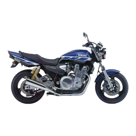
DESCRIPTION Left view ..................... 2-1 Right view................... 2-2 Controls and instruments ..............2-3... - Page 12 D ESCRIPTION EAU00026 Left view 1. Clutch fluid reservoir (page 6-20) 2. Fuel cock (page 3-9) 3. Shock absorber assembly spring preload adjusting rings (page 3-13) 4. Luggage strap holders (page 3-15) 5. Helmet holder lock/seat lock (page 3-11) 6. Shift pedal (page 3-6) 7.
- Page 13 DESCRIPTION Right view 8. Tail/brake light (page 6-31) 14. Air filter element (page 6-11) 9. Luggage strap holders (page 3-15) 15. Fuel tank (page 3-8) 10. Shock absorber assembly spring preload 16. Front brake fluid reservoir (page 6-19) adjusting rings (page 3-13) 17.
- Page 14 DESCRIPTION Controls and instruments 1. Clutch lever (page 3-5) 7. Right handlebar switches (page 3-5) 2. Left handlebar switches (page 3-4) 8. Brake lever (page 3-7) 3. Starter (choke) lever (page 3-10) 9. Throttle grip (page 6-13) 4. Speedometer unit (page 3-3) 10.
-
Page 15: Instrument And Control Functions
INSTRUMENT AND CONTROL FUNCTIONS Main switch/steering lock ..............3-1 Indicator and warning lights .............. 3-2 Speedometer unit ................3-3 Tachometer ..................3-3 Anti-theft alarm (optional) ..............3-3 Fuel gauge ..................3-4 Handlebar switches ................3-4 Clutch lever ..................3-5 Shift pedal ..................3-6 Brake lever .................. -
Page 16: Main Switch/Steering Lock
I NSTRUMENT AND CONTROL FUNCTIONS EAU00027 1. Push. 2. Turn. EAU00029 EAU00040 Main switch/steering lock LOCK EW000016 The steering is locked, and all electrical WARNING The main switch/steering lock controls systems are off. The key can be re- the ignition and lighting systems, and is Never turn the key to “OFF”... -
Page 17: Indicator And Warning Lights
Turn signal indicator lights pushing the start switch, have a “ ” / “ ” Yamaha dealer check the electri- The corresponding indicator light flash- cal circuit. es when the turn signal switch is pushed to the left or right. -
Page 18: Speedometer Unit
INSTRUMENT AND CONTROL FUNCTIONS EAU00109 Anti-theft alarm (optional) This motorcycle can be equipped with an optional anti-theft alarm by a Yamaha dealer. Contact a Yamaha dealer for more information. 1. Tripmeter reset knob 1. Tachometer 2. Tripmeter 2. Tachometer red zone 3. -
Page 19: Fuel Gauge
INSTRUMENT AND CONTROL FUNCTIONS EAU00127 Turn signal switch To signal a right-hand turn, push this switch to “ ”. To signal a left-hand turn, push this switch to “ ”. When released, the switch returns to the cen- ter position. To cancel the turn signal lights, push the switch in after it has re- turned to the center position. -
Page 20: Clutch Lever
INSTRUMENT AND CONTROL FUNCTIONS EAU00143 Start switch “ ” Push this switch to crank the engine with the starter. EC000005 CAUTION: See page 5-1 for starting instruc- tions prior to starting the engine. 1. Engine stop switch 1. Clutch lever 2. -
Page 21: Shift Pedal
INSTRUMENT AND CONTROL FUNCTIONS 1. Clutch lever position adjusting dial 1. Shift pedal 2. Arrow mark EAU00157 Shift pedal The clutch lever is equipped with a The shift pedal is located on the left clutch lever position adjusting dial. To side of the engine and is used in com- adjust the distance between the clutch bination with the clutch lever when... -
Page 22: Brake Lever
INSTRUMENT AND CONTROL FUNCTIONS 1. Brake lever 1. Arrow mark 1. Brake pedal 2. Brake lever position adjusting dial EAU00161 EAU00162 Brake lever Brake pedal The brake lever is equipped with a po- The brake lever is located at the right The brake pedal is on the right side of sition adjusting dial. -
Page 23: Fuel Tank Cap
INSTRUMENT AND CONTROL FUNCTIONS 2. Turn the key counterclockwise to the original position, remove it, and then close the lock cover. NOTE: The fuel tank cap cannot be closed un- less the key is in the lock. In addition, the key cannot be removed if the cap is not properly closed and locked. -
Page 24: Fuel
INSTRUMENT AND CONTROL FUNCTIONS EAU00185 ON: normal position CAUTION: Immediately wipe off spilled fuel with a clean, dry, soft cloth, since fuel may deteriorate painted surfac- es or plastic parts. EAU00191 1. Fuel tank filler tube 1. Arrow mark positioned over “ON” Recommended fuel: 2. -
Page 25: Starter (Choke) Lever
INSTRUMENT AND CONTROL FUNCTIONS RES: reserve position PRI: priming position 1. Arrow mark positioned over “RES” 1. Arrow mark positioned over “PRI” 1. Starter (choke) lever EAU02976 Starter (choke) lever This indicates reserve. With the fuel This indicates prime. With the fuel cock Starting a cold engine requires a richer cock lever in this position, the fuel re- lever in this position, the engine can be... -
Page 26: Seat
INSTRUMENT AND CONTROL FUNCTIONS 1. Unlock. 1. Projection 1. Unlock. 2. Seat holder EAU01721 EAU00260 Seat Helmet holder To install the seat To open the helmet holder, insert the 1. Insert the projection on the front of To remove the seat key into the lock, and then turn the key the seat into the seat holder as 1. -
Page 27: Storage Compartment
This storage compartment is designed the adjusting bolt on each fork leg in di- to hold a genuine Yamaha U-LOCK. rection a. To decrease the spring pre- (Other locks may not fit.) When placing load... -
Page 28: Adjusting The Shock Absorber Assemblies
INSTRUMENT AND CONTROL FUNCTIONS EAU03748 Adjusting the shock absorber assemblies Each shock absorber assembly is equipped with a spring preload adjust- ing ring. EC000015 CAUTION: Never attempt to turn an adjusting 1. Current setting 1. Upper ring (spring preload adjusting ring) mechanism beyond the maximum 2. - Page 29 ,. they may explode due to exces- sive gas pressure. Do not deform or damage the gas cylinders in any way, as this will result in poor damping per- formance. Always have a Yamaha dealer service the shock absorbers. 3-14...
-
Page 30: Luggage Strap Holders
Therefore, can be turned out for easier access. check this system regularly as de- scribed below and have a Yamaha dealer repair it if it does not function properly. 3-15... -
Page 31: Ignition Circuit Cut-Off System
If a malfunction is noted, have a It prevents starting when the trans- Yamaha dealer check the sys- mission is in gear and the side- tem before riding. stand is up, but the clutch lever is not pulled. - Page 32 5. Push the start switch. Does the engine start? The neutral switch may be defective. The motorcycle should not be ridden until checked by a Yamaha dealer. With the engine still running: 6. Move the sidestand up. 7. Keep the clutch lever pulled.
-
Page 33: Pre-Operation Checks
PRE-OPERATION CHECKS Pre-operation check list ..............4-1... - Page 34 • If necessary, add recommended oil to specified level. 6-7–6-8 • Check vehicle for oil leakage. • Check operation. • If soft or spongy, have Yamaha dealer bleed hydraulic system. Front brake • Check fluid level in reservoir. 6-19–6-20 • If necessary, add recommended brake fluid to specified level.
- Page 35 • Check operation of ignition circuit cut-off system. Sidestand switch 3-15 • If system is defective, have Yamaha dealer check vehicle. NOTE: Pre-operation checks should be made each time the motorcycle is used. Such an inspection can be accomplished in a very short time;...
-
Page 37: Operation And Important Riding Points
OPERATION AND IMPORTANT RIDING POINTS Starting a cold engine ............... 5-1 Starting a warm engine ..............5-2 Shifting ....................5-3 Recommended shift points (for Switzerland only) ......5-3 Tips for reducing fuel consumption ........... 5-4 Engine break-in ................. 5-4 Parking ....................5-5... -
Page 38: Starting A Cold Engine
Yamaha dealer check the electrical cir- The transmission is in the neutral Consult a Yamaha dealer re- cuit. position. -
Page 39: Starting A Warm Engine
Yamaha dealer check the electrical circuit. 6. After starting the engine, move the starter (choke) lever back halfway. -
Page 40: Shifting
OPERATION AND IMPORTANT RIDING POINTS EC000048 EAU02941 Recommended shift points CAUTION: (for Switzerland only) Even with the transmission in The recommended shift points during the neutral position, do not acceleration are shown in the table be- coast for long periods of time low. -
Page 41: Tips For Reducing Fuel Consumption
EC000053 CAUTION: Keep the engine speed out of the tachometer red zone. If any engine trouble should oc- cur during the engine break-in period, immediately have a Yamaha dealer check the vehi- cle. -
Page 42: Parking
OPERATION AND IMPORTANT RIDING POINTS EAU00460 Parking When parking, stop the engine, and then remove the key from the main switch. EW000058 WARNING Since the engine and exhaust system can become very hot, park in a place where pedestri- ans or children are not likely to touch them. -
Page 43: Periodic Maintenance And Minor Repair
PERIODIC MAINTENANCE AND MINOR REPAIR Owner’s tool kit ............6-1 Checking and lubricating the throttle grip and cable ..........6-23 Periodic maintenance and lubrication chart ..6-2 Checking and lubricating the brake and Removing and installing the panel .......6-5 shift pedals ............6-24 Checking the spark plugs ........6-6 Checking and lubricating the brake and Engine oil and oil filter element ......6-7... -
Page 44: Owner's Tool Kit
Periodic inspection, adjustment and lu- ence required for a particular job, have brication will keep your vehicle in the a Yamaha dealer perform it for you. safest and most efficient condition pos- EW000063 sible. The most important points of in-... -
Page 45: Periodic Maintenance And Lubrication Chart
The annual checks must be performed every year, except if a kilometer-based maintenance is performed instead. From 50,000 km, repeat the maintenance intervals starting from 10,000 km. Items marked with an asterisk should be performed by a Yamaha dealer as they require special tools, data and techni- cal skills. - Page 46 PERIODIC MAINTENANCE AND MINOR REPAIR ODOMETER READING (× 1,000 km) ANNUAL ITEM CHECK OR MAINTENANCE JOB CHECK √ √ √ √ √ • Check for cracks or damage. Brake hoses • Replace. (See NOTE on page 6-4.) Every 4 years √...
- Page 47 PERIODIC MAINTENANCE AND MINOR REPAIR ODOMETER READING (× 1,000 km) ANNUAL ITEM CHECK OR MAINTENANCE JOB CHECK √ √ √ Engine oil filter element • Replace. Front and rear brake √ √ √ √ √ √ • Check operation. switches √...
-
Page 48: Removing And Installing The Panel
PERIODIC MAINTENANCE AND MINOR REPAIR 1. Panel A 1. Screw (× 2) 1. Projection 2. Grommet EAU01777 EAU01551 Removing and installing the Panel A To install the panel To remove the panel panel 1. Place the panel in the original po- 1. -
Page 49: Checking The Spark Plugs
Do not attempt to diagnose such problems yourself. Instead, have a Yamaha dealer check the motorcycle. 3. Check each spark plug for elec- trode erosion and excessive car- bon or other deposits, and replace 1. -
Page 50: Engine Oil And Oil Filter Element
PERIODIC MAINTENANCE AND MINOR REPAIR 3. Install the spark plug with the EAU03759 Engine oil and oil filter spark plug wrench, and then tight- element en it to the specified torque. The engine oil level should be checked before each ride. In addition, the oil Tightening torque: must be changed and the oil filter ele- Spark plug:... - Page 51 PERIODIC MAINTENANCE AND MINOR REPAIR 1. Engine oil level check window 1. Engine oil drain bolt 1. Oil filter element drain screw 2. Maximum level mark 2. Bolt To change the engine oil (with or 3. Minimum level mark 3. Oil filter element cover without oil filter element replace- 3.
- Page 52 PERIODIC MAINTENANCE AND MINOR REPAIR 8. Install the oil filter element drain screw, and then tighten it to the specified torque. Tightening torque: Oil filter element drain screw: 7 Nm (0.7 m·kg) 9. Install the engine oil drain bolt, and 1.
- Page 53 3.0 L If the oil level warning light flickers With oil filter element or remains on, immediately turn the replacement: engine off and have a Yamaha deal- 3.35 L er check the vehicle. Total amount (dry engine): 4.2 L 12. Turn the engine off, and then...
-
Page 54: Cleaning The Air Filter Element
PERIODIC MAINTENANCE AND MINOR REPAIR 1. Air filter case cover 1. Air filter element 2. Screw (× 4) 4. Pull the air filter element out. 5. Lightly tap the air filter element to EAU01755 remove most of the dust and dirt, Cleaning the air filter element and then blow the remaining dirt The air filter element should be cleaned... -
Page 55: Adjusting The Carburetors
Therefore, most car- buretor adjustments should be left to a Yamaha dealer, who has the neces- sary professional knowledge and expe- rience. The adjustment described in the following section, however, may be... -
Page 56: Adjusting The Engine Idling Speed
Yamaha dealer adjust it. Engine idling speed: 1,000–1,100 r/min NOTE: If the specified idling speed cannot be obtained as described above, have a Yamaha dealer make the adjustment. 6-13... -
Page 57: Adjusting The Valve Clearance
2.50 bar) 2.50 bar) from occurring, the valve clearance regarding the specified tires. 250 kPa 290 kPa must be adjusted by a Yamaha dealer 90 kg–maximum (2.50 kg/cm (2.90 kg/cm 2.50 bar) 2.90 bar) at the intervals specified in the periodic... - Page 58 Yamaha dealer fied maximum load for the replace the tire immediately. vehicle.
- Page 59 PERIODIC MAINTENANCE AND MINOR REPAIR EW000079 Always make sure that the valve WARNING caps are securely installed to Have a Yamaha dealer replace prevent air pressure leakage. excessively worn tires. Besides Use only the tire valves and being illegal, operating...
-
Page 60: Wheels
Other tires may run fore each ride. If any damage is the danger of bursting at super a. Distance between brake pedal and footrest found, have a Yamaha dealer re- high speeds. place the wheel. Do not attempt EAU00712... -
Page 61: Rear Brake Light Switch Adjustment
If Yamaha dealer bleed the system be- necessary, adjust the brake light switch fore operating the motorcycle. Air in as follows. -
Page 62: Checking The Front And Rear Brake Pads
NOTE: The rear brake fluid reservoir is located cator almost touches the brake disc, behind panel A. (See page 6-5 for panel have a Yamaha dealer replace the removal and installation procedures.) brake pads as a set. 6-19... -
Page 63: Changing The Brake Fluid
EAU03792 Clutch Changing the brake fluid mal for the brake fluid level to Have a Yamaha dealer change the gradually go down. However, if the brake fluid at the intervals specified in brake fluid level goes down sud- the periodic maintenance and lubrica- denly, have a Yamaha dealer tion chart. -
Page 64: Drive Chain Slack
PERIODIC MAINTENANCE AND MINOR REPAIR EAU00745 Drive chain slack The drive chain slack should be checked before each ride and adjusted if necessary. To check the drive chain slack 1. Place the motorcycle on the cen- terstand. a. Drive chain slack 1. -
Page 65: Lubricating The Drive Chain
PERIODIC MAINTENANCE AND MINOR REPAIR EAU03006 ECA00052 NOTE: Lubricating the drive chain CAUTION: Using the alignment marks on each The drive chain must be cleaned and side of the swingarm, make sure that Do not use engine oil or any other lubricated at the intervals specified in both chain pullers are in the same posi- lubricants for the drive chain, as... -
Page 66: Checking And Lubricating The Cables
If a cable is damaged replaced if necessary. or does not move smoothly, have a NOTE: Yamaha dealer check or replace it. Since the throttle grip must be removed to access the throttle cable end, the Recommended lubricant:... -
Page 67: Checking And Lubricating The Brake And Shift Pedals
PERIODIC MAINTENANCE AND MINOR REPAIR EAU03370 EAU03164 Checking and lubricating the Checking and lubricating the brake and shift pedals brake and clutch levers The operation of the brake and shift The operation of the brake and clutch pedals should be checked before each levers should be checked before each ride, and the pedal pivots should be lu- ride, and the lever pivots should be lu-... -
Page 68: Checking And Lubricating The Centerstand And Sidestand
EW000114 WARNING If the centerstand or sidestand does not move up and down smoothly, have a Yamaha dealer check or re- pair it. 6-25... -
Page 69: Checking The Steering
If any free Securely support the motorcycle so position. play can be felt, have a Yamaha that there is no danger of it falling 2. While applying the front brake, dealer check or repair the steer- over. -
Page 70: Checking The Wheel Bearings
To charge the battery working near batteries. In case Have a Yamaha dealer charge the bat- of contact, administer the fol- tery as soon as possible if it seems to lowing FIRST AID. - Page 71 If you do not have ac- least once a month and fully cess to a sealed-type (MF) bat- charge it if necessary. tery charger, have a Yamaha 3. Fully charge the battery before in- dealer charge your battery. stallation.
-
Page 72: Replacing The Fuses
4. If the fuse immediately blows If a fuse is blown, replace it as follows. again, have a Yamaha dealer 1. Turn the key to “OFF” and turn off check the electrical system. the electrical circuit in question. - Page 73 4. Place a new bulb into position, and 5. Install the bulb cover, and then then secure it with the bulb holder. connect the coupler. 6. Install the headlight unit by install- ing the screws. 7. Have a Yamaha dealer adjust the headlight beam if necessary. 6-30...
- Page 74 PERIODIC MAINTENANCE AND MINOR REPAIR 1. Socket 1. Screw 1. Turn signal light bulb 2. Remove the defective bulb by EAU00856 EAU03497 Replacing the tail/brake light Replacing a turn signal light pushing it in and turning it counter- bulb bulb clockwise.
-
Page 75: Front Wheel
4. Remove the brake calipers by re- EW000122 remove the wheel. moving the bolts. WARNING ECA00047 It is advisable to have a Yamaha CAUTION: dealer service the wheel. Do not pull the brake lever after the Securely support the motor- brake caliper has been removed,... - Page 76 PERIODIC MAINTENANCE AND MINOR REPAIR NOTE: Make sure that there is enough space between the brake pads before install- ing the brake calipers onto the brake discs. 7. Install the brake hose holders by installing the bolts. 8. Install the front wheel axle pinch bolt, and then tighten the wheel 1.
-
Page 77: Rear Wheel
EW000122 6. Push the wheel forward, and then WARNING remove the drive chain from the It is advisable to have a Yamaha rear sprocket. dealer service the wheel. Securely support the motor- NOTE: cycle so that there is no danger The drive chain does not need to be of it falling over. - Page 78 PERIODIC MAINTENANCE AND MINOR REPAIR 7. While supporting the brake caliper EAU03793 To install the rear wheel Tightening torques: bracket, pull the wheel axle out. 1. Insert the wheel axle through the Axle nut: 8. Remove the wheel. brake caliper bracket and wheel 150 Nm (15.0 m·kg) ECA00048 from the right-hand side.
-
Page 79: Troubleshooting
However, should your motorcycle require any repair, take it to a Yamaha dealer, whose skilled technicians have the necessary tools, experience, and know-how to service the motorcycle properly. -
Page 80: Troubleshooting Chart
Remove the spark plugs and check the electrodes. The engine does not start. Have a Yamaha dealer check the vehicle. Check the battery. 4. Battery The engine turns over The battery is good. -
Page 81: Motorcycle Care And Storage
MOTORCYCLE CARE AND STORAGE Care ....................7-1 Storage ....................7-4... -
Page 82: Cleaning
M OTORCYCLE CARE AND STORAGE EAU03429 Care Before cleaning Cleaning 1. Cover the muffler outlets with plas- ECA00010 While the open design of a motorcycle CAUTION: tic bags after the engine has reveals the attractiveness of the tech- Avoid using strong acidic wheel cooled down. - Page 83 MOTORCYCLE CARE AND STORAGE Do not use any harsh chemical For motorcycles equipped with After riding in the rain, near the sea or products on plastic parts. Be a windshield: Do not use strong on salt-sprayed roads sure to avoid using cloths or cleaners or hard sponges as Since sea salt or salt sprayed on roads sponges which have been in...
- Page 84 NOTE: 4. To prevent corrosion, it is recom- Consult a Yamaha dealer for advice on mended to apply a corrosion pro- what products to use. tection spray...
- Page 85 MOTORCYCLE CARE AND STORAGE Storage Long-term a. Remove the spark plug caps and Before storing your motorcycle for spark plugs. several months: b. Pour a teaspoonful of engine oil Short-term 1. Follow all the instructions in the into each spark plug bore. Always store your motorcycle in a cool, “Care”...
- Page 86 MOTORCYCLE CARE AND STORAGE 6. Lubricate all control cables and 9. Remove the battery and fully the pivoting points of all levers and charge it. Store it in a cool, dry pedals as well as of the sidestand/ place and charge it once a month. centerstand.
-
Page 87: Specifications
SPECIFICATIONS Specifications ..................8-1 Conversion table ................8-5... - Page 88 S PECIFICATIONS EAU01038 Specifications CS-01E Model XJR1300/XJR1300SP Engine oil Dimensions Type -20 -10 10 20 30 40 50 ˚C Overall length 2,175 mm (except for SF, N, S) SAE 10W-30 2,250 mm (for SF, N, S) Overall width 775 mm...
- Page 89 SPECIFICATIONS Fuel 1.292 Type Regular unleaded gasoline 1.115 Fuel tank capacity 21 L Chassis Fuel reserve amount 4.5 L Frame type Double cradle Carburetor Caster angle 25.5 ° Manufacturer MIKUNI Trail 100 mm Model × quantity BS36 × 4 Tires Spark plug Front Manufacturer/model...
- Page 90 SPECIFICATIONS 90 kg–maximum* Suspension Front 250 kPa (2.50 kg/cm , 2.50 bar) Front Telescopic fork Rear 290 kPa (2.90 kg/cm , 2.90 bar) Rear Swingarm High-speed riding Springs/shock absorbers Front 250 kPa (2.50 kg/cm , 2.50 bar) Front Coil spring / oil damper Rear 290 kPa (2.90 kg/cm , 2.90 bar)
- Page 91 SPECIFICATIONS Bulb voltage, wattage × quantity 12 V, 60/55 W × 1 Headlight 12 V, 5/21 W × 2 Tail/brake light 12 V, 4 W × 1 Auxiliary light 12 V, 21 W × 4 Turn signal light 12 V, 1.7 W × 4 Meter lighting 12 V, 1.7 W ×...
-
Page 92: Conversion Table
SPECIFICATIONS EAU01064 Conversion table CS-02E Conversion table All specification data in this manual are listed in SI and METRIC TO IMPERIAL METRIC UNITS. Metric unit Multiplier Imperial unit Use this table to convert METRIC unit data to IMPERIAL m·kg 7.233 ft·lb m·kg 86.794... -
Page 93: Consumer Information
CONSUMER INFORMATION Identification numbers ............... 9-1 Key identification number ..............9-1 Vehicle identification number ............. 9-1 Model label ..................9-2... - Page 94 Record the key identification number, vehicle identification number and mod- el label information in the spaces pro- vided below for assistance when ordering spare parts from a Yamaha dealer or for reference in case the vehi- cle is stolen. 1. Key identification number 1.
-
Page 95: Model Label
The model label is affixed to the frame under the seat. (See page 3-11 for seat removal and installation procedures.) Record the information on this label in the space provided. This information will be needed when ordering spare parts from a Yamaha dealer. - Page 96 INDEX Air filter element, cleaning ......6-11 Engine break-in ........5-4 Main switch/steering lock ......3-1 Anti-theft alarm ........3-3 Engine oil and oil filter element ....6-7 Model label ..........9-2 Engine stop switch........3-5 Battery ...........6-27 Neutral indicator light .......3-2 Brake and clutch levers, checking and Front fork, adjusting.......
- Page 97 INDEX Steering, checking ......... 6-26 Storage............ 7-4 Storage compartment ......3-12 Tachometer ..........3-3 Tail/brake light bulb, replacing ....6-31 Throttle cable free play, adjusting ..6-13 Throttle grip and cable, checking and lubricating..........6-23 Tires ............6-14 Tool kit............. 6-1 Troubleshooting........
- Page 100 YAMAHA MOTOR CO., LTD. PRINTED ON RECYCLED PAPER PRINTED IN JAPAN 2000 · 9 - 0.4 × 1 CR...
Need help?
Do you have a question about the XJR1300SP and is the answer not in the manual?
Questions and answers