Yamaha XJR1300 Owner's Manual
Hide thumbs
Also See for XJR1300:
- Owner's manual (102 pages) ,
- Manual (8 pages) ,
- Owner's manual (95 pages)
Table of Contents
Advertisement
Quick Links
Advertisement
Table of Contents
Troubleshooting

Related Manuals for Yamaha XJR1300


Summary of Contents for Yamaha XJR1300
- Page 1 OWNER’S MANUAL XJR1300 5WM-28199-E1...
- Page 2 EAU26941 DECLARATION of CONFORMITY Company: MORIC CO., LTD. Address: 1450-6 Mori Mori-Machi Shuchi-gun Shizuoka 437-0292 Japan Hereby declare that the product: Kind of equipment: IMMOBILIZER Type-designation: 5SL-00, 5VS-00, 5VX-00, 3HT-00, 5UX-00, 5UX-10, 5KS-00 and 5KS-10 is in compliance with following norm(s) or documents: R&TTE Directive(1999/5/EC) EN300 330-2 v1.1.1(2001-6), EN60950(2000) Two or Three-Wheel Motor Vehicles Directive(97/24/EC: Chapter 8, EMC)
- Page 3 Yamaha a reputation for dependability. Please take the time to read this manual thoroughly, so as to enjoy all advantages of your XJR1300. The owner’s manual does not only instruct you in how to operate, inspect and maintain your motorcycle, but also in how to safeguard yourself and others from trouble and injury.
-
Page 4: Important Manual Information
This manual should be considered a permanent part of this motorcycle and should remain with it even if the motorcycle is subsequently sold. Yamaha continually seeks advancements in product design and quality. Therefore, while this manual contains the most current product information available at the time of printing, there may be minor discrepancies between your motorcycle and this manual. - Page 5 IMPORTANT MANUAL INFORMATION EAU10200 XJR1300 OWNER’S MANUAL ©2003 by Yamaha Motor Co., Ltd. 1st edition, September 2003 All rights reserved. Any reprinting or unauthorized use without the written permission of Yamaha Motor Co., Ltd. is expressly prohibited. Printed in Japan.
-
Page 6: Table Of Contents
TABLE OF CONTENTS SAFETY INFORMATION ....1-1 Adjusting the front fork ....3-16 Adjusting the engine idling Adjusting the shock absorber speed ........6-12 DESCRIPTION ........2-1 assemblies ........ 3-17 Adjusting the throttle cable free Left view ..........2-1 Luggage strap holders ....3-18 play ........... - Page 7 TABLE OF CONTENTS Checking the steering ....6-25 Checking the wheel bearings ..6-26 Battery ..........6-26 Replacing the fuses ......6-28 Replacing the headlight bulb ..6-29 Replacing a tail/brake light bulb ...6-30 Replacing a turn signal light bulb ...........6-30 Replacing the auxiliary light bulb ...........6-31 Front wheel ........6-32 Rear wheel ........6-33...
-
Page 8: Safety Information
SAFETY INFORMATION EAU10250 AND/OR WHEN MADE NECES- • Ride where other motorists can SARY BY MECHANICAL CONDI- see you. Avoid riding in another MOTORCYCLES SINGLE TIONS. motorist’s blind spot. TRACK VEHICLES. THEIR SAFE USE Many motorcycle accidents in- AND OPERATION ARE DEPENDENT Safe riding volve inexperienced operators. - Page 9 Modifications made to this motorcycle other motorists can see you. the single most critical factor in the pre- not approved by Yamaha, or the re- The posture of the operator and vention or reduction of head injuries. moval of original equipment, may ren- passenger is important for proper Always wear an approved helmet.
- Page 10 Since Yamaha cannot should be kept to a minimum. 203 kg (448 lb). When loading within test all other accessories that may be •...
- Page 11 SAFETY INFORMATION Gasoline and exhaust gas • Do not park the motorcycle on a GASOLINE IS HIGHLY FLAMMA- slope or soft ground, otherwise it BLE: may fall over. • Always turn the engine off when • Do not park the motorcycle near refueling.
-
Page 12: Description
DESCRIPTION EAU10410 Left view 1. Clutch fluid reservoir (page 6-18) 2. Fuel cock (page 3-13) 3. Shock absorber assembly spring preload adjusting ring (page 3-17) 4. Luggage strap holder (page 3-18) 5. Seat lock/helmet holder (page 3-14/page 3-15) 6. Throttle stop screw (page 6-12) 7. -
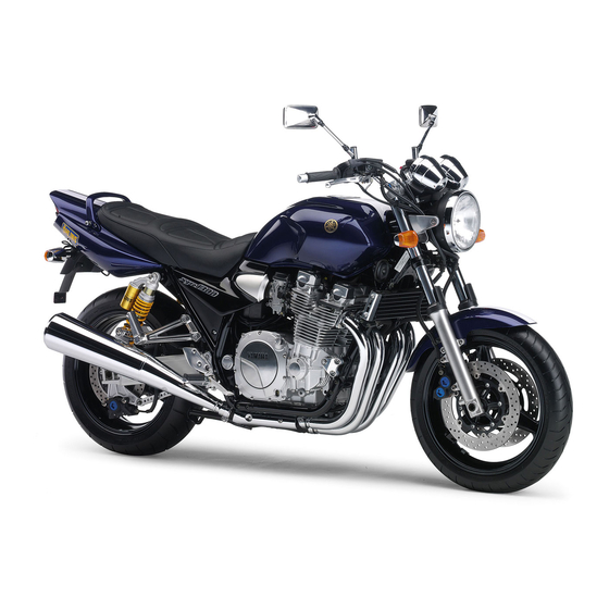
Page 13: Right View
DESCRIPTION EAU10420 Right view 1. Tail/brake light (page 6-30) 12.Headlight (page 6-29) 2. Luggage strap holder (page 3-18) 13.Engine oil filler cap (page 6-8) 3. Shock absorber assembly spring preload adjusting ring (page 3-17) 14.Engine oil level check window (page 6-8) 4. -
Page 14: Controls And Instruments
DESCRIPTION EAU10430 Controls and instruments 1. Clutch lever (page 3-9) 2. Left handlebar switches (page 3-7) 3. Starter (choke) lever (page 3-14) 4. Speedometer (page 3-5) 5. Multi-function display (page 3-6) 6. Tachometer (page 3-5) 7. Right handlebar switches (page 3-7) 8. -
Page 15: Instrument And Control Functions
Do not expose any key to exces- a Yamaha dealer to have them re-reg- sively high temperatures. istered. Do not use the key with the red Do not place any key close to bow for driving. -
Page 16: Main Switch/Steering Lock
INSTRUMENT AND CONTROL FUNCTIONS EAU10471 EAU33590 To lock the steering Main switch/steering lock All electrical circuits are supplied with power; the meter lighting, taillight and auxiliary light come on, and the engine can be started. The key cannot be re- moved. -
Page 17: Indicator And Warning Lights
INSTRUMENT AND CONTROL FUNCTIONS To unlock the steering EAU10920 EAU11001 (Parking) Indicator and warning lights The steering is locked, the taillight and auxiliary light are on, and the hazard light can be turned on, but all other electrical systems are off. The key can be removed. - Page 18 This warning light comes on when the Make sure there are no other immobi- Yamaha dealer check the electrical cir- engine oil level is low. lizer keys close to the main switch, and cuit.
-
Page 19: Speedometer
Do not operate the engine in the ta- If the tachometer displays such an error chometer red zone. code, note the circuit-specific number Red zone: 9500 r/min and above of r/min, and then have a Yamaha deal- er check the vehicle. -
Page 20: Multi-Function Display
INSTRUMENT AND CONTROL FUNCTIONS ECA10040 EAU33572 Multi-function display NOTE: CAUTION: Be sure to turn the key to “ON” before When the tachometer displays an er- using the “SELECT” and “RESET” but- ror code, the vehicle should be tons. checked as soon as possible in or- der to avoid engine damage. -
Page 21: Anti-Theft Alarm (Optional)
Contact a Yamaha dealer for symbol “ ” will flash. If this occurs, more information. have a Yamaha dealer check the elec- trical circuit. Clock mode To set the clock: 1. Turn the key to “ON”. - Page 22 INSTRUMENT AND CONTROL FUNCTIONS Right position. To cancel the turn signal EAU12731 Hazard switch “ ” lights, push the switch in after it has re- With the key in the “ON” or “ ” posi- turned to the center position. tion, use this switch to turn on the haz- ard light (simultaneous flashing of all EAU12500...
-
Page 23: Clutch Lever
INSTRUMENT AND CONTROL FUNCTIONS EAU12830 EAU12870 Clutch lever Shift pedal 1. Clutch lever position adjusting dial 2. Arrow mark 1. Clutch lever 1. Shift pedal The clutch lever is equipped with a The clutch lever is located at the left The shift pedal is located on the left clutch lever position adjusting dial. -
Page 24: Brake Lever
INSTRUMENT AND CONTROL FUNCTIONS EAU26822 The brake lever is equipped with a po- EAU12941 Brake lever Brake pedal sition adjusting dial. To adjust the dis- tance between the brake lever and the handlebar grip, turn the adjusting dial while holding the lever pushed away from the handlebar grip. -
Page 25: Fuel Tank Cap
INSTRUMENT AND CONTROL FUNCTIONS EAU13070 EAU13210 Fuel tank cap NOTE: Fuel The fuel tank cap cannot be closed un- less the key is in the lock. In addition, the key cannot be removed if the cap is not properly closed and locked. EWA11090 WARNING Make sure that the fuel tank cap is... -
Page 26: Fuel Tank Breather Hose
Your Yamaha engine has been de- signed to use regular unleaded gaso- line with a research octane number of 91 or higher. If knocking (or pinging) oc-... -
Page 27: Catalytic Converter
INSTRUMENT AND CONTROL FUNCTIONS EAU13440 EAU13570 Catalytic converter Fuel cock This vehicle is equipped with a catalytic The fuel cock supplies fuel from the converter in the muffler. tank to the carburetors while also filter- ing it. EWA10860 WARNING The fuel cock lever positions are ex- plained as follows and shown in the il- The exhaust system is hot after op- eration. -
Page 28: Starter (Choke) Lever
INSTRUMENT AND CONTROL FUNCTIONS EAU13590 EAU13900 Starter (choke) lever “ ” Seat To remove the seat 1. Insert the key into the seat lock, and then turn it as shown. 1. Arrow mark positioned over “PRI” 1. Starter (choke) lever “ ”... -
Page 29: Helmet Holder
3. Remove the key. This storage compartment is designed key as shown. NOTE: to hold an optional genuine Yamaha U- To lock the helmet holder, turn the key Make sure that the seat is properly se- LOCK. (Other locks may not fit.) When to the original position, and then re- cured before riding. -
Page 30: Adjusting The Front Fork
INSTRUMENT AND CONTROL FUNCTIONS When washing the motorcycle, be EAU14720 Adjusting the front fork NOTE: careful not to let any water enter the Align the appropriate groove on the ad- This front fork is equipped with spring storage compartment. justing mechanism with the top of the preload adjusting bolts. -
Page 31: Adjusting The Shock Absorber Assemblies
INSTRUMENT AND CONTROL FUNCTIONS EAU14900 Setting: Adjusting the shock absorber Minimu (soft) / standard assemblies Each shock absorber assembly is equipped with a spring preload adjust- ing ring. ECA10100 Medium CAUTION: Never attempt to turn an adjusting mechanism beyond the maximum or 1. -
Page 32: Luggage Strap Holders
(See further down for an explanation of Always have a Yamaha dealer 1. Luggage strap holder the ignition circuit cut-off system.) service the shock absorbers. There are four luggage strap holders,... -
Page 33: Ignition Circuit Cut-Off System
INSTRUMENT AND CONTROL FUNCTIONS below and have a Yamaha dealer re- EAU15321 Ignition circuit cut-off system pair it if it does not function proper- The ignition circuit cut-off system (com- prising the sidestand switch, clutch switch and neutral switch) has the fol- lowing functions. - Page 34 5. Push the start switch. Does the engine start? The neutral switch may be defective. The motorcycle should not be ridden until checked by a Yamaha dealer. With the engine still running: 6. Move the sidestand up. 7. Keep the clutch lever pulled.
-
Page 35: Pre-Operation Checks
PRE-OPERATION CHECKS EAU15591 The condition of a vehicle is the owner’s responsibility. Vital components can start to deteriorate quickly and unexpectedly, even if the vehicle remains unused (for example, as a result of exposure to the elements). Any damage, fluid leakage or loss of tire air pressure could have serious consequences. -
Page 36: Pre-Operation Check List
• If necessary, add recommended fluid to specified level. • Check hydraulic system for leakage. • Make sure that operation is smooth. • Check cable free play. Throttle grip 6-12, 6-22 • If necessary, have Yamaha dealer adjust cable free play and lubricate cable and grip housing. - Page 37 Chassis fasteners — • Tighten if necessary. Instruments, lights, signals • Check operation. — and switches • Correct if necessary. • Check operation of ignition circuit cut-off system. Sidestand switch 3-18 • If system is defective, have Yamaha dealer check vehicle.
-
Page 38: Operation And Important Riding Points
Become thoroughly familiar following conditions must be met: Yamaha dealer check the electrical cir- The transmission is in the neutral with all operating controls and cuit. position. their functions before riding. -
Page 39: Starting A Warm Engine
“ON”, or if it does not go off after starting the en- gine with sufficient engine oil, have a Yamaha dealer check the electrical circuit. 6. After starting the engine, move the 1. Shift pedal starter (choke) back halfway. -
Page 40: Tips For Reducing Fuel Consumption
OPERATION AND IMPORTANT RIDING POINTS ECA10260 EAU16800 Shift up points: Tips for reducing fuel CAUTION: 1st → 2nd: 23 km/h (14 mi/h) consumption 2nd → 3rd: 36 km/h (22 mi/h) Even with the transmission in 3rd → 4th: 50 km/h (31 mi/h) Fuel consumption depends largely on the neutral position, do not 4th →... -
Page 41: Engine Break-In
ECA10380 period, immediately have a CAUTION: Yamaha dealer check the vehi- EAU17091 Never park in an area where there cle. 0–1000 km (0–600 mi) are fire hazards such as grass or Avoid prolonged operation above 4000 other flammable materials. -
Page 42: Periodic Maintenance And Minor Repair
If you are not familiar with mainte- certain maintenance work correctly. nance work, have a Yamaha dealer do it for you. NOTE: If you do not have the tools or experi- ence required for a particular job, have a Yamaha dealer perform it for you. -
Page 43: Periodic Maintenance And Lubrication Chart
The annual checks must be performed every year, except if a kilometer-based maintenance is performed in- stead. From 50000 km, repeat the maintenance intervals starting from 10000 km. Items marked with an asterisk should be performed by a Yamaha dealer as they require special tools, data and technical skills. ODOMETER READING (× 1000 km) - Page 44 PERIODIC MAINTENANCE AND MINOR REPAIR ODOMETER READING (× 1000 km) ANNUAL ITEM CHECK OR MAINTENANCE JOB CHECK √ √ √ √ √ • Check for cracks or damage. 9 * Brake hoses • Replace. Every 4 years √ √ √ √...
- Page 45 PERIODIC MAINTENANCE AND MINOR REPAIR ODOMETER READING (× 1000 km) ANNUAL ITEM CHECK OR MAINTENANCE JOB CHECK • Change. √ √ √ √ √ √ Engine oil • Check oil level and vehicle for oil leakage. √ √ √ Engine oil filter element • Replace. Front and rear brake √...
-
Page 46: Removing And Installing Panels
PERIODIC MAINTENANCE AND MINOR REPAIR EAU18771 Removing and installing panels The panels shown need to be removed to perform some of the maintenance jobs described in this chapter. Refer to this section each time a panel needs to be removed and installed. 1. - Page 47 PERIODIC MAINTENANCE AND MINOR REPAIR ECA12830 EAU19192 Panel C CAUTION: The area shown is not a storage To remove the panel compartment. Placing items here Remove the bolts, and then take the could block the air intake resulting panel off. in poor engine performance or en- gine damage.
-
Page 48: Checking The Spark Plugs
1. Spark plug cap 1. Spark plug gap problems yourself. Instead, have a 2. Remove the spark plug as shown, Yamaha dealer check the vehicle. Spark plug gap: with the spark plug wrench includ- 0.8–0.9 mm (0.031–0.035 in) ed in the owner’s tool kit. -
Page 49: Engine Oil And Oil Filter Element
PERIODIC MAINTENANCE AND MINOR REPAIR 2. Clean the surface of the spark plug EAU19691 Engine oil and oil filter NOTE: gasket and its mating surface, and The engine oil should be between the element then wipe off any grime from the minimum and maximum level marks. - Page 50 PERIODIC MAINTENANCE AND MINOR REPAIR 2. Place an oil pan under the engine 8. Install the oil filter element cover by to collect the used oil. aligning the projection on the cover 3. Remove the engine oil filler cap with the slot in the crankcase, in- and drain bolt to drain the oil from stalling the bolt, then tightening it the crankcase.
-
Page 51: Cleaning The Air Filter Element
If the oil level warning light flickers 3.35 L (3.54 US qt) (2.95 Imp.qt) 1. Air filter case cover or remains on, immediately turn the 2. Screw engine off and have a Yamaha dealer ECA11620 CAUTION: 4. Pull the air filter element out. check the vehicle. -
Page 52: Adjusting The Carburetors
Therefore, most carbu- air filter case. retor adjustments should be left to a The engine should never be op- Yamaha dealer, who has the neces- erated without the air filter ele- sary professional knowledge and expe- ment installed, otherwise the rience. -
Page 53: Adjusting The Engine Idling Speed
Yamaha dealer make the adjustment. sary, have a Yamaha dealer adjust it. screw in direction (a). To decrease the engine idling speed, turn the screw in direction (b). -
Page 54: Adjusting The Valve Clearance
250 kPa (36 psi) (2.50 kgf/cm²) Rear: from occurring, the valve clearance regarding the specified tires. 250 kPa (36 psi) (2.50 kgf/cm²) must be adjusted by a Yamaha dealer 90–203 kg (198–448 lb): at the intervals specified in the periodic Tire air pressure Front: maintenance and lubrication chart. - Page 55 Tire information glass fragments in it, or if the sidewall is weight evenly on both sides. cracked, have a Yamaha dealer re- Adjust the suspension and tire place the tire immediately. air pressure with regard to the load.
- Page 56 Tire air valve: tires listed below have been ap- TR412 proved this model Valve core: Yamaha Motor Co., Ltd. #9000A (original) Always make sure that the valve EWA10600 caps are securely installed to WARNING prevent air pressure leakage. This motorcycle is fitted with super- Use only the tire valves and high-speed tires.
-
Page 57: Cast Wheels
If the clutch fore each ride. If any damage is lever free play does become excessive, found, have a Yamaha dealer re- and shifting becomes rough or clutch place the wheel. Do not attempt slippage occurs, causing poor acceler-... -
Page 58: Rear Brake Light Switch Adjustment
PERIODIC MAINTENANCE AND MINOR REPAIR the braking performance, which may EAU22290 3. Install the panel. Rear brake light switch result in loss of control and an acci- adjustment dent. 1. Rear brake light switch 2. Rear brake light switch adjusting nut The rear brake light switch, which is ac- tivated by the brake pedal, is properly adjusted when the brake light comes... -
Page 59: Checking The Front And Rear Brake Pads
If a brake pad has worn to the point that the wear indicator groove has almost disappeared, have a Yamaha dealer replace the brake pads as a set. 1. Brake pad wear indicator groove 1. Minimum level mark... - Page 60 However, if the brake fluid level goes down sud- 1. Minimum level mark DOT 4 brake fluid denly, have a Yamaha dealer Insufficient brake fluid may allow air to check the cause. Refill with the same type of brake enter the brake or clutch systems, pos- fluid.
-
Page 61: Changing The Brake And Clutch Fluids
20.0–30.0 mm (0.79–1.18 in) clutch fluids The drive chain slack should be checked before each ride and adjusted Have a Yamaha dealer change the 5. If the drive chain slack is incorrect, if necessary. brake and clutch fluids at the intervals adjust it as follows. -
Page 62: Lubricating The Drive Chain
PERIODIC MAINTENANCE AND MINOR REPAIR EAU23020 Tightening torque: Lubricating the drive chain Axle nut: The drive chain must be cleaned and 150 Nm (15.0 m·kgf, 108 ft·lbf) lubricated at the intervals specified in the periodic maintenance and lubrica- tion chart, otherwise it will quickly wear out, especially when riding in dusty or wet areas. -
Page 63: Checking And Lubricating The Cables
If a cable is damaged periodic maintenance chart. or does not move smoothly, have a Yamaha dealer check or replace it. Recommended lubricant: Engine oil EWA10720 WARNING... -
Page 64: Checking And Lubricating The Brake And Shift Pedals
PERIODIC MAINTENANCE AND MINOR REPAIR EAU23131 EAU23140 Recommended lubricant: Checking and lubricating the Checking and lubricating the Lithium-soap-based grease (all-pur- brake and shift pedals brake and clutch levers pose grease) Brake lever Clutch lever The operation of the brake and shift pedals should be checked before each The operation of the brake and clutch ride, and the pedal pivots should be lu-... -
Page 65: Checking And Lubricating The Centerstand And Sidestand
Lithium-soap-based grease (all-pur- centerstand and sidestand If the centerstand or sidestand does pose grease) not move up and down smoothly, have a Yamaha dealer check or re- pair it. Recommended lubricant: Lithium-soap-based grease (all-pur- pose grease) The operation of the centerstand and... -
Page 66: Checking The Front Fork
Securely support the vehicle so that fork does not operate smoothly, damage and excessive oil leakage. there is no danger of it falling over. have a Yamaha dealer check or re- pair it. To check the operation 2. Hold the lower ends of the front 1. -
Page 67: Checking The Wheel Bearings
If there is play in the wheel hub or if the wheel does not turn smoothly, have a Yamaha dealer check the wheel bearings. 1. Negative battery terminal 2. Positive battery terminal... - Page 68 Storing a discharged battery can cause permanent To charge the battery battery damage. Have a Yamaha dealer charge the bat- To charge a sealed-type (MF) tery as soon as possible if it seems to battery, a special (constant-volt- have discharged. Keep in mind that the age) battery charger is required.
-
Page 69: Replacing The Fuses
4. If the fuse immediately blows If a fuse is blown, replace it as follows. again, have a Yamaha dealer 1. Turn the key to “OFF” and turn off check the electrical system. the electrical circuit in question. -
Page 70: Replacing The Headlight Bulb
PERIODIC MAINTENANCE AND MINOR REPAIR EAU23792 EWA10790 Replacing the headlight bulb WARNING This model is equipped with a quartz Headlight bulbs get very hot. There- bulb headlight. If the headlight bulb fore, keep flammable products away burns out, replace it as follows. from a lit headlight bulb, and do not 1. -
Page 71: Replacing A Tail/Brake Light Bulb
6. Install the headlight unit by install- clockwise. ing the screws. 7. Have a Yamaha dealer adjust the headlight beam if necessary. 1. Screw 2. Remove the defective bulb by pushing it in and turning it counter- 1. -
Page 72: Replacing The Auxiliary Light Bulb
PERIODIC MAINTENANCE AND MINOR REPAIR EAU33541 Replacing the auxiliary light bulb If the auxiliary light bulb burns out, re- place it as follows. 1. Remove the headlight unit by re- moving the screws. 1. Turn signal light bulb 1. Auxiliary light bulb socket 3. -
Page 73: Front Wheel
2. Insert the wheel axle. EWA10820 3. Install the brake calipers by install- WARNING ing the bolts. It is advisable to have a Yamaha NOTE: dealer service the wheel. Make sure that there is enough space Securely support the motor-... -
Page 74: Rear Wheel
EAU25160 To remove the rear wheel EWA10820 WARNING It is advisable to have a Yamaha dealer service the wheel. Securely support the motor- cycle so that there is no danger of it falling over. - Page 75 PERIODIC MAINTENANCE AND MINOR REPAIR 5. Loosen the locknuts, and then turn 8. Remove the brake caliper bracket 7. Tighten the axle nut, brake caliper the drive chain slack adjusting bolt and the wheel. bolts and brake torque rod nut to on each side of the swingarm fully the specified torques.
-
Page 76: Troubleshooting
However, should your motorcycle require any repair, take it to a Yamaha dealer, whose skilled technicians have the necessary tools, experience, and know-how to service the motorcycle properly. -
Page 77: Troubleshooting Chart
Remove the spark plugs and check the electrodes. The engine does not start. Have a Yamaha dealer check the vehicle. Check the battery. 4. Battery The engine turns over The battery is good. -
Page 78: Motorcycle Care And Storage
MOTORCYCLE CARE AND STORAGE EAU26040 ucts onto seals, gaskets, sprock- cleaning products, solvent or Care ets, the drive chain and wheel thinner, fuel (gasoline), rust re- While the open design of a motorcycle axles. Always rinse the dirt and de- movers or inhibitors, brake flu- reveals the attractiveness of the tech- greaser off with water. - Page 79 MOTORCYCLE CARE AND STORAGE After normal use ECA10790 4. To prevent corrosion, it is recom- CAUTION: Remove dirt with warm water, a mild mended to apply a corrosion pro- detergent, and a soft, clean sponge, tection spray metal, Do not use warm water since it in- and then rinse thoroughly with clean including chrome- and nickel-plat- creases the corrosive action of the...
-
Page 80: Storage
NOTE: and spark plugs. To prevent corrosion, avoid Consult a Yamaha dealer for advice on b. Pour a teaspoonful of engine oil damp cellars, stables (because what products to use. into each spark plug bore. - Page 81 MOTORCYCLE CARE AND STORAGE EWA10950 than 30 °C (90 °F)]. For more in- WARNING formation on storing the battery, To prevent damage or injury from see page 6-26. sparking, make sure to ground the NOTE: spark plug electrodes while turning Make any necessary repairs before the engine over.
-
Page 82: Specifications
SPECIFICATIONS Dimensions: Engine oil: Carburetor: Overall length: Type: Manufacturer: 2175 mm (85.6 in) SAE10W30 or SAE10W40 or SAE15W40 MIKUNI Overall width: or SAE20W40 or SAE20W50 Type x quantity: 775 mm (30.5 in) BSR37 x 4 Overall height: Spark plug(s): -20 -10 10 20 30 40 50 ˚C 1115 mm (43.9 in) Manufacturer/model:... - Page 83 SPECIFICATIONS 3rd: Tire air pressure (measured on cold Recommended fluid: 33/21 (1.571) DOT 4 tires): 4th: Rear brake: Loading condition: 31/24 (1.292) Type: 0–90 kg (0–198 lb) 5th: Single disc brake Front: 29/26 (1.115) Operation: 250 kPa (36 psi) (2.50 kgf/cm²) Chassis: Right foot operation Rear:...
- Page 84 SPECIFICATIONS Headlight: Parking lighting fuse: 10.0 A Bulb type: Backup fuse: Halogen bulb 10.0 A Bulb voltage, wattage x quantity: Headlight: 12 V, 60 W/55.0 W × 1 Tail/brake light: 12 V, 5.0/21.0 W × 2 Front turn signal light: 12 V, 21.0 W ×...
-
Page 85: Consumer Information
Record the key identification number, vehicle identification number and mod- el label information in the spaces pro- vided below for assistance when ordering spare parts from a Yamaha dealer or for reference in case the vehi- cle is stolen. KEY IDENTIFICATION NUMBER: 1. - Page 86 1. Model label The model label is affixed to the frame under the seat. (See page 3-14.) Record the information on this label in the space provided. This information will be needed when ordering spare parts from a Yamaha dealer.
- Page 87 INDEX Engine stop switch ........3-8 Air filter element, cleaning ....6-10 Oil level warning light ......3-4 Anti-theft alarm (optional) ....... 3-7 Front and rear brake pads, checking ..6-18 Auxiliary light bulb, replacing ....6-31 Front fork, adjusting ......3-16 Panels, removing and installing ....6-5 Front fork, checking.......6-25 Parking............
- Page 88 INDEX Throttle grip and cable, checking and lubricating ........... 6-22 Tires ............6-13 Tool kit ............ 6-1 Troubleshooting ........6-35 Troubleshooting chart ......6-36 Turn signal indicator lights ...... 3-3 Turn signal light bulb, replacing .... 6-30 Turn signal switch ........3-8 Valve clearance, adjusting ....
- Page 90 YAMAHA MOTOR CO., LTD. PRINTED ON RECYCLED PAPER PRINTED IN JAPAN 2003.09-0.4×1 CR...
Need help?
Do you have a question about the XJR1300 and is the answer not in the manual?
Questions and answers