Yamaha XJR1300 Owner's Manual
1999
Hide thumbs
Also See for XJR1300:
- Owner's manual (102 pages) ,
- Manual (8 pages) ,
- Owner's manual (98 pages)
Table of Contents
Advertisement
Quick Links
Advertisement
Chapters
Table of Contents
Troubleshooting

Related Manuals for Yamaha XJR1300


Summary of Contents for Yamaha XJR1300
- Page 1 OWNER’S MANUAL XJR1300 XJR1300SP 5EA-28199-E2...
- Page 2 Yamaha a reputation for dependability. Please take the time to read this manual thoroughly, so as to enjoy all your XJR1300/ XJR1300SP’s advantages. The owner’s manual does not only instruct you in how to operate, inspect and maintain your motorcycle, but also in how to safeguard yourself and others from trouble and injury.
- Page 3 This manual should be considered a permanent part of this motorcycle and should remain with it even if the motorcycle is subsequently sold. Yamaha continually seeks advancements in product design and quality. Therefore, while this manual contains the most current product information available at the time of printing, there may be minor discrepancies between your motorcycle and this manual.
-
Page 4: Important Manual Information
IMPORTANT MANUAL INFORMATION EW000002 WARNING PLEASE READ THIS MANUAL CAREFULLY AND COMPLETELY BEFORE OPERATING THIS MOTORCYCLE. - Page 5 IMPORTANT MANUAL INFORMATION EAU00008 XJR1300/XJR1300SP OWNER’S MANUAL © 1999 by Yamaha Motor Co., Ltd. 1st Edition, July 1999 All rights reserved. Any reprinting or unauthorized use without the written permission of Yamaha Motor Co., Ltd. is expressly prohibited. Printed in Japan.
-
Page 6: Table Of Contents
EAU00009 TABLE OF CONTENTS 1 GIVE SAFETY THE RIGHT OF WAY 2 DESCRIPTION 3 INSTRUMENT AND CONTROL FUNCTIONS 4 PRE-OPERATION CHECKS 5 OPERATION AND IMPORTANT RIDING POINTS 6 PERIODIC MAINTENANCE AND MINOR REPAIR 7 MOTORCYCLE CARE AND STORAGE 8 SPECIFICATIONS 9 CONSUMER INFORMATION INDEX... -
Page 8: Give Safety The Right Of Way
GIVE SAFETY THE RIGHT OF WAY GIVE SAFETY THE RIGHT OF WAY..........1-1... - Page 9 G IVE SAFETY THE RIGHT OF WAY EAU00021 Motorcycles are fascinating vehicles, which can give you an unsurpassed feeling of power and freedom. However, they also impose certain limits, which you must accept; even the best motorcycle does not ignore the laws of physics. Regular care and maintenance are essential for preserving your motorcycle’s value and operating condition.
-
Page 10: Description
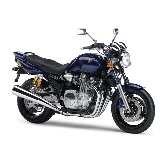
DESCRIPTION Left view ..................... 2-1 Right view................... 2-2 Controls/Instruments ................2-3... - Page 11 D ESCRIPTION EAU00026 Left view 1. Clutch fluid reservoir (page 6-18) 2. Fuel cock (page 3-10) 3. Rear shock absorber spring preload adjusting ring (page 3-13) 4. Luggage strap holders (page 3-15) 5. Helmet holder/seat lock (page 3-12 / page 3-11) 6.
- Page 12 DESCRIPTION Right view 8. Tail/brake light (page 6-27) 13. Air filter (page 6-10) 9. Luggage strap holders (page 3-15) 14. Fuel tank (page 3-9) 10. Tool kit (page 6-1) 15. Front brake fluid reservoir (page 6-18) 11. Rear brake fluid reservoir (page 6-18) 16.
- Page 13 DESCRIPTION Controls/Instruments 1. Clutch lever (page 3-7) 7. Right handlebar switches (page 3-6) 2. Left handlebar switches (page 3-5) 8. Front brake lever (page 3-8) 3. Starter (choke) “ ” (page 3-11) 9. Throttle grip (page 6-12) 4. Speedometer (page 3-4) 10.
-
Page 14: Instrument And Control Functions
INSTRUMENT AND CONTROL FUNCTIONS Main switch/steering lock ........3-1 Fuel tank cap ............3-9 Indicator lights ............3-2 Fuel ..............3-9 Oil level indicator circuit check......3-3 Fuel cock............3-10 Speedometer ............3-4 Starter (choke) “ ”........... 3-11 Tachometer ............3-4 Seat..............3-11 Antitheft alarm (optional) ........3-4 Helmet holder............. -
Page 15: Main Switch/Steering Lock
I NSTRUMENT AND CONTROL FUNCTIONS EAU00027 1. Push 2. Turn EAU00029* EAU00040 Main switch/steering lock LOCK EW000016 The steering is locked in this position WARNING The main switch controls the ignition and all electrical circuits are switched and lighting systems. Its operation is Never turn the key to “OFF”... -
Page 16: Indicator Lights
INSTRUMENT AND CONTROL FUNCTIONS EAU01590 EAU00061 (Parking) Neutral indicator light “ ” The steering is locked in this position, This indicator comes on when the and the taillight and auxiliary light come transmission is in neutral. on but all other circuits are off. The key can be removed in this position. -
Page 17: Oil Level Indicator Circuit Check
Turn the engine stop switch to “ ”. light will come on for a few seconds and then go off. If the indicator light does not come on, ask a Yamaha dealer to in- spect the electrical circuit. Wait a few seconds (see NOTE). -
Page 18: Speedometer
INSTRUMENT AND CONTROL FUNCTIONS EAU00109 Antitheft alarm (optional) An antitheft alarm can be equipped to this motorcycle. Consult your Yamaha dealer to obtain and install the alarm. 1. Reset knob 1. Tachometer 2. Tripmeter 2. Red zone 3. Odometer EAU00101 4. -
Page 19: Fuel Gauge
INSTRUMENT AND CONTROL FUNCTIONS EAU00127 Turn signal switch To signal a right-hand turn, push the switch to “ ”. To signal a left-hand turn, push the switch to “ ”. Once the switch is released it will return to the center position. -
Page 20: Instrument And Control Functions
INSTRUMENT AND CONTROL FUNCTIONS EAU00143 Start switch “ ” The starter motor cranks the engine when pushing the start switch. EC000005 CAUTION: See starting instructions prior to starting the engine. 1. Engine stop switch 2. Lights switch 3. Start switch “ ”... -
Page 21: Instrument And Control Functions
INSTRUMENT AND CONTROL FUNCTIONS 1. Clutch lever 1. Adjusting dial 1. Shift pedal 2. Arrow mark EAU00153 EAU00157 Clutch lever Shift pedal To adjust the distance between the The clutch lever is located on the left This motorcycle is equipped with a con- clutch lever and the handlebar grip, handlebar. -
Page 22: Front Brake Lever
INSTRUMENT AND CONTROL FUNCTIONS 1. Front brake lever 1. Arrow mark 1. Rear brake pedal 2. Adjusting dial EAU00161 EAU00162 Front brake lever Rear brake pedal To adjust the front brake lever position, The front brake lever is located on the The rear brake pedal is on the right turn the brake lever adjusting dial while right handlebar and is equipped with a... -
Page 23: Fuel Tank Cap
INSTRUMENT AND CONTROL FUNCTIONS NOTE: This tank cap cannot be closed unless the key is in the lock. The key cannot be removed if the cap is not locked properly. EW000023 WARNING Be sure the cap is properly installed and locked in place before riding the 1. -
Page 24: Fuel Cock
INSTRUMENT AND CONTROL FUNCTIONS EAU00185 ON: normal position RES: reserve position CAUTION: Always wipe off spilled fuel immedi- ately with a dry and clean soft cloth. Fuel may deteriorate painted surfac- es or plastic parts. EAU00191 Recommended fuel: 1. Arrow mark positioned over “ON” 1. -
Page 25: Starter (Choke)
INSTRUMENT AND CONTROL FUNCTIONS PRI: priming position 1. Arrow mark positioned over “PRI” 1. Starter (choke) “ ” 1. Open EAU02976 EAU01721 Starter (choke) “ ” Seat This stands for “prime”. If the engine Starting a cold engine requires a richer To remove has been allowed to run out of fuel, turn air-fuel mixture. -
Page 26: Helmet Holder
This compartment is designed to store key in the lock and turn it as shown. seat into the holder, then push down a genuine Yamaha U-LOCK. (Other To lock the helmet holder, replace the the seat. locks may not fit.) Be sure the lock is holder in its original position. -
Page 27: Front Fork Adjustment
INSTRUMENT AND CONTROL FUNCTIONS 1. Spring preload adjusting bolt 1. Setting 1. Upper adjusting ring 2. Front fork cap bolt 2. Lower adjusting ring EAU00285 Front fork adjustment EC000013 EAU01783 Rear shock absorber CAUTION: This front fork is equipped with spring adjustment preload adjusting bolts. - Page 28 Do not deform or damage the cylinders in any way. Cylinder damage will result in poor damping performance. Take your shock absorbers to a Yamaha dealer for any service. 3-14...
-
Page 29: Luggage Strap Holders
Please check carefully PULL IN CLUTCH LEVER AND the operating instructions listed be- PUSH START SWITCH. low and if there is any indication of a malfunction, return the motorcycle ENGINE WILL START. to a Yamaha dealer immediately for repair. 3-15... - Page 30 INSTRUMENT AND CONTROL FUNCTIONS CD-08E CLUTCH SWITCH IS OK. SIDESTAND IS DOWN. ENGINE WILL STALL. SIDESTAND SWITCH IS OK. 3-16...
-
Page 32: Pre-Operation Checks
PRE-OPERATION CHECKS Pre-operation check list..............4-1... -
Page 33: Pre-Operation Check List
P RE-OPERATION CHECKS EAU01114 Owners are personally responsible for their vehicle’s condition. Your motorcycle’s vital functions can start to deteriorate quickly and unexpectedly, even if it remains unused (for instance, if it is exposed to the elements). Any damage, fluid leak or loss of tire pressure could have serious consequences. - Page 34 PRE-OPERATION CHECKS ITEM CHECKS PAGE • Make sure that all nuts, bolts and screws are properly tightened. Chassis fasteners — • Tighten if necessary. • Check fuel level. Fuel 3-9 ~ 3-10 • Fill with fuel if necessary. Lights, signals and •...
-
Page 36: Operation And Important Riding Points
OPERATION AND IMPORTANT RIDING POINTS Starting the engine................5-1 Starting a warm engine ..............5-4 Shifting ....................5-4 Recommended shift points (for Switzerland only) ......5-5 Tips for reducing fuel consumption ............ 5-5 Engine break-in .................. 5-5 Parking ....................5-6... -
Page 37: Starting The Engine
The engine their functions. Consult can be started only under one of the Yamaha dealer regarding any following conditions: control or function that you do The transmission is in neutral. not thoroughly understand. The sidestand is up, the transmis-... - Page 38 OPERATION AND IMPORTANT RIDING POINTS CF-33E TURN THE MAIN SWITCH TO “ON” AND THE ENGINE STOP SWITCH TO “ ”. IF TRANSMISSION IS IN NEUTRAL AND IF TRANSMISSION IS IN GEAR AND SIDESTAND IS DOWN, SIDESTAND IS UP, PUSH THE START SWITCH. PULL IN THE CLUTCH LEVER AND PUSH THE ENGINE WILL START.
- Page 39 NOTE: start switch, consult a Yamaha deal- If the engine fails to start, release the start switch, wait a few seconds, then 6. After starting the engine, move the try again.
-
Page 40: Starting A Warm Engine
OPERATION AND IMPORTANT RIDING POINTS EAU01258 EC000048 Starting a warm engine CAUTION: The starter (choke) is not required Do not coast for long periods when the engine is warm. with the engine off, and do not EC000046 tow the motorcycle a long dis- CAUTION: tance. -
Page 41: Recommended Shift Points (For Switzerland Only)
OPERATION AND IMPORTANT RIDING POINTS EAU02941 EAU00424 EAU01128 Recommended shift points Tips for reducing fuel Engine break-in (for Switzerland only) consumption There is never a more important period in the life of your motorcycle than the The recommended shift points are Your motorcycle’s fuel consumption period between zero and 1,600 km. -
Page 42: Parking
1,600 km and beyond Proceed with normal riding. EC000053* CAUTION: Never let the engine speed enter the red zone. If any engine trouble should oc- cur during the break-in period, consult a Yamaha dealer imme- diately. -
Page 44: Periodic Maintenance And Minor Repair
PERIODIC MAINTENANCE AND MINOR REPAIR Tool kit..............6-1 Drive chain lubrication........6-20 Periodic maintenance and lubrication....6-2 Cable inspection and lubrication ......6-20 Panel removal and installation ......6-5 Throttle cable and grip lubrication ...... 6-21 Panel A ..............6-5 Brake and shift pedal lubrication ......6-21 Spark plugs............6-6 Brake and clutch lever lubrication ...... -
Page 45: Tool Kit
If you do not have necessary tools re- brication will keep your motorcycle in quired during a service operation, take the safest and most efficient condition your motorcycle to a Yamaha dealer for possible. Safety is an obligation of the service. motorcycle owner. The maintenance... -
Page 46: Periodic Maintenance And Minor Repair
PERIODIC MAINTENANCE AND MINOR REPAIR EAU00473 PERIODIC MAINTENANCE AND LUBRICATION CP-01E EVERY 6,000 km 12,000 km INITIAL ITEM CHECKS AND MAINTENANCE JOBS (1,000 km) 6 months 12 months (whichever (whichever comes first) comes first) • Check fuel hoses and vacuum hose for cracks or damage. Fuel line •... - Page 47 PERIODIC MAINTENANCE AND MINOR REPAIR EVERY 6,000 km 12,000 km INITIAL ITEM CHECKS AND MAINTENANCE JOBS (1,000 km) 6 months 12 months (whichever (whichever comes first) comes first) • Check tread depth and for damage. • Replace if necessary. Tires •...
- Page 48 • Correct if necessary. • Change. (Warm engine before draining.) Engine oil filter element • Replace. * Since these items require special tools, data and technical skills, they should be serviced by a Yamaha dealer. EAU02971 NOTE: The air filter needs more frequent service if you are riding in unusually wet or dusty areas.
-
Page 49: Panel Removal And Installation
PERIODIC MAINTENANCE AND MINOR REPAIR 1. Panel A 1. Screw ( 2) 1. Projection 2. Pull out 2. Grommet EAU01777 Panel removal and installation To install EAU01551 Panel A The panel illustrated needs to be re- Insert the projection into the grommet To remove moved to perform some of the mainte- and tighten the panel screws. -
Page 50: Spark Plugs
Do not attempt to diagnose such prob- lems yourself. Instead, take the motor- cycle to a Yamaha dealer. You should periodically remove and inspect the spark plugs because heat and deposits will cause any spark plug to slowly 1. -
Page 51: Engine Oil
PERIODIC MAINTENANCE AND MINOR REPAIR EAU01784* Tightening torque: Engine oil Spark plug: Oil level inspection 17.5 Nm (1.75 m·kg) 1. Place the motorcycle on the cen- terstand. Warm up the engine for NOTE: several minutes. If a torque wrench is not available when you are installing a spark plug, a good NOTE: Be sure the motorcycle is positioned... - Page 52 PERIODIC MAINTENANCE AND MINOR REPAIR 1. Oil level window 1. Engine oil drain bolt 1. Oil filter drain screw 2. Maximum level mark 2. Oil filter cover bolt Engine oil and oil filter element re- 3. Minimum level mark 4. Remove the oil filter drain screw, placement 2.
- Page 53 PERIODIC MAINTENANCE AND MINOR REPAIR 9. Fill engine with oil. Install the oil fill- er cap and tighten. Recommended oil: See page 8-1. Oil quantity: Total amount: 4.2 L Periodic oil change: 1. Oil filter element 1. Projection 3.0 L 2.
-
Page 54: Air Filter
If the indicator light flickers or re- specified intervals. It should be cleaned mains on, immediately stop the en- more frequently if you are riding in un- gine and consult with a Yamaha usually wet or dusty areas. dealer. 1. Remove the seat. (See page 3-11 for seat removal and installation procedures.) -
Page 55: Carburetor Adjustment
Most adjustments 1,000 to 2,000 r/min. Occasionally should be left to a Yamaha dealer who rev the engine to 4,000 to has the professional knowledge and 5,000 r/min. The engine is warm experience to do so. -
Page 56: Throttle Cable Free Play Inspection
There should be a free play of 3 ~ speed and in direction b to de- 5 mm at the throttle grip. If the free play is incorrect, ask a Yamaha dealer to crease engine speed. make this adjustment. Standard idle speed:... -
Page 57: Tires
PERIODIC MAINTENANCE AND MINOR REPAIR EAU00658 CE-33E EW000083 Maximum load* 207 kg Tires WARNING Cold tire pressure Front Rear To ensure maximum performance, Proper loading of your motorcycle 250 kPa 250 kPa long service and safe operation, note Up to 90 kg load* (2.50 kg/cm (2.50 kg/cm is important for several characteris-... - Page 58 Yamaha dealer immediately. Brakes, tires, and relat- ed wheel parts replacement should 1. Side wall 1. Tire valve be left to a Yamaha Service Techni- a. Tread depth 2. Valve core cian. 3. Valve cap with seal Tire inspection CE-26E...
- Page 59 The fol- Bridgestone 120/70ZR17 (58W) BT57F proved by Yamaha Motor Co., Michelin 120/70ZR17 (58W) MACADAM90X lowing points must be observed in Ltd. for this model. No guaran- order for you to make fully effective...
-
Page 60: Wheels
The top of the brake pedal should be anced whenever either one is positioned 40 mm below the top of the changed or replaced. Failure to footrest. If not, ask a Yamaha dealer to have a wheel balanced can result adjust it. in poor performance, adverse han- dling characteristics, and short- ened tire life. -
Page 61: Checking The Front And Rear Brake Pads
If the indicator is 1. Remove panel A. (See page 6-5 ALMOST in contact with the disc plate, for panel removal and installation ask a Yamaha dealer to replace the procedures.) pads. 2. Hold the switch body so it does not rotate while turning the adjusting nut. -
Page 62: Inspecting The Brake Fluid Level
If the brake fluid level is performance. Have a Yamaha dealer check the low, be sure to inspect the brake pads cause if the brake fluid level goes for wear and the brake and clutch sys- Recommended brake fluid: DOT 4 down. -
Page 63: Brake Fluid Replacement
EAU00742 Brake fluid replacement The brake fluid should be replaced only by trained Yamaha service personnel. Have the Yamaha dealer replace the following components during periodic maintenance or when they are dam- aged or leaking: oil seals (every two years) a. -
Page 64: Drive Chain Lubrication
150 Nm (15.0 m·kg) only kerosene to clean the drive chain. a Yamaha dealer to replace it. Wipe it dry, and thoroughly lubricate it with SAE 30 ~ 50W motor oil. Do not... -
Page 65: Throttle Cable And Grip Lubrication
PERIODIC MAINTENANCE AND MINOR REPAIR EAU00773 Throttle cable and grip lubrication The throttle twist grip assembly should be greased at the time that the cable is lubricated, since the grip must be re- moved to get at the end of the throttle cable. -
Page 66: Center And Sidestand Lubrication
Recommended lubricant: EC000098 Engine oil CAUTION: If any damage or unsmooth move- EW000114 ment is found with the front fork, WARNING consult a Yamaha dealer. If the center and/or sidestand does not move smoothly, consult a Yamaha dealer. 6-22... -
Page 67: Steering Inspection
Hold the lower end of the front forks and try to move them forward and backward. If any free play can be felt, ask a Yamaha dealer to inspect and adjust the steer- ing. Inspection is easier if the front wheel is removed. - Page 68 If you do not have a sealed- Batteries produce explosive gases. type battery charger, contact Keep sparks, flame, cigarettes etc., your Yamaha dealer. away. Ventilate when charging or Always make sure the connec- using in an enclosed space. Always...
-
Page 69: Fuse Replacement
If any fuse is blown, turn off the main switch and the switch of the circuit in question. Install a new fuse of specified amperage. Turn on the switches and see if the electrical device operates. If the fuse immediately blows again, con- sult a Yamaha dealer. 6-25... - Page 70 4. Put a new bulb into position and quer thinner. secure it in place with the bulb holder. 5. Install the bulb cover and the headlight connector. If the head- light beam adjustment is neces- sary, ask a Yamaha dealer to make that adjustment. 6-26...
- Page 71 PERIODIC MAINTENANCE AND MINOR REPAIR 1. Screw 1. Bulb 2. Remove the defective bulb by EAU00856* EAU01095 Tail/brake light bulb Turn signal light bulb pushing it inward and turning it replacement replacement counterclockwise. 1. Remove the seat. 1. Remove the screw and the lens. 3.
-
Page 72: Front Wheel Removal
Do not depress the brake lever when WARNING and the calipers by removing the the disc and caliper are separated. bolts. It is advisable to have a Yamaha 4. Loosen the pinch bolt and wheel dealer service the wheel. axle. Securely support the motor- 5. -
Page 73: Front Wheel Installation
PERIODIC MAINTENANCE AND MINOR REPAIR 5. Tighten the wheel axle, pinch bolt and caliper bolts to the specified torques. Tightening torque: Wheel axle: 73 Nm (7.3 m·kg) Pinch bolt: 19 Nm (1.9 m·kg) Caliper bolt: 2. Lift up the wheel between the front EAU01758* 40 Nm (4.0 m·kg) Front wheel installation... -
Page 74: Rear Wheel Removal
EW000122 5. Loosen the locknuts and chain ad- WARNING justing nuts on each side of the It is advisable to have a Yamaha swingarm. dealer service the wheel. 6. Push the wheel forward and re- Securely support the motor- move the drive chain. -
Page 75: Rear Wheel Installation
Make sure there is enough gap If your motorcycle requires any repair, between the brake pads before in- bring it to a Yamaha dealer. The skilled stalling the caliper onto the brake technicians at a Yamaha dealership disc. -
Page 76: Troubleshooting Chart
Remove spark plugs and check electrodes. Engine doesn’t start, go to battery Dry. Ask a Yamaha dealer to inspect. check. 4. Battery Engine turns over Battery good. quickly. Engine doesn’t start, ask a Yamaha Use the electric starter. -
Page 78: Motorcycle Care And Storage
MOTORCYCLE CARE AND STORAGE Care ....................7-1 Storage....................7-4... - Page 79 M OTORCYCLE CARE AND STORAGE EAU01517 Care Before cleaning Cleaning 1. Cover up the muffler outlets with After normal use The exposure of its technology makes plastic bags. Remove dirt with warm water, a neutral a motorcycle charming but also vulner- 2.
-
Page 80: Motorcycle Care And Storage
MOTORCYCLE CARE AND STORAGE ECA00010 Do not use any harsh chemical For motorcycles equipped with CAUTION: products on plastic parts. Be a windshield: Do not use strong Avoid using strong acidic wheel sure to avoid using cloths or cleaners or hard sponges as cleaners, especially on spoked sponges which have been in they... - Page 81 MOTORCYCLE CARE AND STORAGE 1. Clean your motorcycle with cold After cleaning EWA00001 WARNING water and soap after the engine 1. Dry the motorcycle with a chamois Make sure that there is no oil or wax has cooled down. or an absorbing cloth. on the brakes and tires.
- Page 82 NOTE: “OFF” position: Turn the fuel cock To prevent corrosion, avoid Consult a Yamaha dealer for advice on to “OFF”. damp cellars, stables (because what products to use. 4. Fill up the fuel tank and add fuel...
- Page 83 MOTORCYCLE CARE AND STORAGE a. Remove the spark plug caps and 6. Lubricate all control cables and 9. Remove the battery and fully spark plugs. the pivoting points of all levers and charge it. Store it in a cool, dry b.
-
Page 84: Specifications
SPECIFICATIONS Specifications ..................8-1 HOW TO USE THE CONVERSION TABLE ........8-5... -
Page 85: Specifications
S PECIFICATIONS EAU01038 Specifications Model XJR1300/XJR1300SP Engine oil Dimensions Type -20˚ -10˚ 0˚ 10˚ 20˚ 30˚ 40˚ 50˚C Overall length 2,250 mm (for SF, N, S) SAE 10W/30 2,175 mm (except for SF, N, S) SAE 10W/40 Overall width 775 mm... - Page 86 SPECIFICATIONS Fuel 1.115 Type Regular unleaded gasoline Chassis Fuel tank capacity 21 L Frame type Double cradle Fuel reserve amount 4.5 L Caster angle 25° 30 Carburetor Trail 100 mm Type quantity BS36 Tires Manufacturer MIKUNI Front Spark plug Type Tubeless Manufacturer/Type NGK / DPR8EA-9 or...
- Page 87 SPECIFICATIONS 90 kg load ~ maximum Suspension load* Front Front 250 kPa (2.50 kg/cm , 2.50 bar) Type Telescopic fork Rear 290 kPa (2.90 kg/cm , 2.90 bar) Rear High speed riding Type Swingarm Front 250 kPa (2.50 kg/cm , 2.50 bar) Shock absorbers Rear 290 kPa (2.90 kg/cm...
- Page 88 SPECIFICATIONS Bulb voltage, wattage quantity Headlight 12 V, 60/55 W Tail/brake light 12 V, 5/21 W Auxiliary light 12 V, 4 W Turn signal lights 12 V, 21 W Meter light 12 V, 1.7 W Neutral indicator light 12 V, 1.7 W High beam indicator light 12 V, 3.4 W Oil level indicator light...
-
Page 89: How To Use The Conversion Table
SPECIFICATIONS EAU01064 HOW TO USE THE CONVERSION TABLE CS-02E CONVERSION TABLE All specification data in this manual are listed in SI and METRIC TO IMPERIAL METRIC UNITS. Metric unit Multiplier Imperial unit Use this table to convert METRIC unit data to IMPERIAL m·kg 7.233 ft·lb... -
Page 90: Consumer Information
CONSUMER INFORMATION Identification number records............. 9-1 Key identification number ..............9-1 Vehicle identification number.............. 9-1 Model label..................9-2... -
Page 91: Identification Number Records
Record the key identification number, vehicle identification number and mod- el label information in the spaces pro- vided for assistance when ordering spare parts from a Yamaha dealer or for reference in case the vehicle is sto- len. 1. Key identification number 1. -
Page 92: Consumer Information
The model label is affixed to the frame under the seat. (See page 3-11 for seat removal procedures.) Record the infor- mation on this label in the space pro- vided. This information will be needed to order spare parts from your Yamaha dealer. -
Page 93: Left View
I NDEX 1 0 - Front fork inspection ......6-22 Front wheel installation ......6-29 Air filter ..........6-10 Key identification number ......9-1 Front wheel removal ......6-28 Antitheft alarm (optional) ......3-4 Fuel ............3-9 Left view...........2-1 Fuel cock..........3-10 Battery ...........6-23 Lights switch ..........3-6 Fuel gauge .......... - Page 94 INDEX Seat............3-11 Valve clearance adjustment ....6-12 Shifting ............ 5-4 Vehicle identification number....9-1 Shift pedal ..........3-7 Sidestand ..........3-15 Wheel bearings ........6-23 Sidestand/clutch switch operation Wheels..........6-16 check ..........3-15 Spark plugs ..........6-6 Specifications .......... 8-1 Speedometer...........
- Page 95 YAMAHA MOTOR CO., LTD. PRINTED ON RECYCLED PAPER PRINTED IN JAPAN 99 · 7 - 0.3...
Need help?
Do you have a question about the XJR1300 and is the answer not in the manual?
Questions and answers