Advertisement
Quick Links
C
H
A
I
N
D
C
H
A
I
N
D
IMPORTANT!
PLEASE READ THIS MANUAL CAREFULLY BEFORE USING THE BIKE.
For Customer Service, please contact: support@sunnyhealthfitness.com
R
I
V
E
I
N
D
R
I
V
E
I
N
D
S
F
-
B
S
F
-
B
O
W
N
E
R
O
W
N
E
R
O
O
R
C
Y
C
O
O
R
C
Y
1
0
0
2
C
1
0
0
2
C
'
S
M
A
N
U
A
L
'
S
M
A
N
U
A
L
L
I
N
G
B
I
C
L
I
N
G
B
I
K
E
K
E
Advertisement

Subscribe to Our Youtube Channel
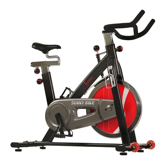
Summary of Contents for Sunny SF-B1002C
- Page 1 ’ ’ IMPORTANT! PLEASE READ THIS MANUAL CAREFULLY BEFORE USING THE BIKE. For Customer Service, please contact: support@sunnyhealthfitness.com...
-
Page 2: Important Safety Information
IMPORTANT SAFETY INFORMATION We thank you for choosing our product. To ensure your safety and health, please use this equipment correctly. It is important to read this entire manual before assembling and using the equipment. Safe and effective use can only be achieved if the equipment is assembled, maintained and used properly. -
Page 3: Exploded View
EXPLODED VIEW 19 19... -
Page 4: Parts List
PARTS LIST DESCRIPTION DESCRIPTION Main frame Bearing 6001-2RZ NBK Spacer Φ18*Φ12.1*22 Saddle post Handlebar Nut M12*1*H6*S19 Handlebar post Nut M12*1*H19.5*S19 Washer d12*Φ24*2.0 Front stabilizer Rear stabilizer Nut M12*1.0*H11*S18 Small chain wheel two ways 16 Seat slider teeth Nut M35*1*Φ44*3.5 Nut M8*H7.5*S13 Adjusting screw M8*83*Φ12*5 Screw M10*25*S6 Big chain wheel... - Page 5 EVA pad Crank cover End cap Φ38*14 Cow leather pad t5*25*138 Screw M5*20*Φ8.5 Screw ST4.8*16*Φ10 Screw M5*18*Φ12 Plastic washer φ6.5*Φ25*6 Screw M5*12*Φ10 Plastic washer φ6.5*Φ25*2 Screw M5*20*Φ8.5 Nut M5*H4*S8 Washer d6*Φ12*1.2 Shipping rear tube Bolt M6*12*S10 Shipping front tube Screw M6*12*Φ12 Allen wrench S6 Nut M5*H9*S8 Spanner S13-14-15...
-
Page 6: Hardware Package
HARDWARE PACKAGE #9 (M10*25*S6) 4PCS #10 (d10*Φ 20*2.0) 4PCS #19 (M10*25*S6) 2PCS #20 (d10*Φ 20*1.5) 2PCS... - Page 7 ASSEMBLY INSTRUCTIONS STEP 1: A. Unscrew the screws (17) with Allen wrench (78), then remove and discard the shipping rear tube (76) and the shipping front tube (77); B. You can save these parts for future packaging and transportation of the bike if desired.
- Page 8 STEP 2: #9 M10*25*S6 4PCS #10 d10*Φ 20*2.0 4PCS A. Secure front stabilizer (5) and rear stabilizer (6) to main frame (1) with screws (9) and washers (10).
- Page 9 STEP 3: #22 M5*12*Φ 8.5 2PCS #23 d5*Φ 13 2PCS A. Secure water bottle holder (21) to main frame (1) with screws (22) and washers (23). B. Secure pedals (41L/R) to the cranks (47L/R). The Left pedal has reversed threading, and must be screwed counter-clockwise to tighten; the right pedal has normal threading and can be screwed clockwise to tighten.
- Page 10 STEP 4: A. Insert saddle post (2) into main frame (1), and adjust it to desired position, then tighten it with knob (16). B. Insert seat slider (7) into saddle post (2), and adjust it to desired position, then tighten it with knob (16). C.
- Page 11 STEP 5: #19 M10*25 2PCS #20 d10*Φ 20*1.5 2PCS 19 19 A. Insert handlebar post (4) into main frame (1), and adjust it to desired position, then tighten it with knob (16). B. Secure handlebar (3) to handlebar post (4) with screws (19) and washers (20).
- Page 12 ADJUSTMENTS If the bike is unbalanced, please adjust it as seen in the picture to the left. Unscrew the nut (49) by turning clockwise (diagram A), then rotate foot pad (15) until the bike is balanced. Lastly, tighten the nut (49) by turning it counter-clockwise (diagram B).
- Page 13 RESISTANCE ADJUSTMENTS Rotate the knob clockwise to increase the resistance. Rotate the knob counter-clockwise to decrease the resistance. Push the knob down to enforce the brake, and stop the bike immediately. ,2014 Version: May 6...


Need help?
Do you have a question about the SF-B1002C and is the answer not in the manual?
Questions and answers