Table of Contents

Subscribe to Our Youtube Channel
Related Manuals for Sunny SF-B1712


Summary of Contents for Sunny SF-B1712
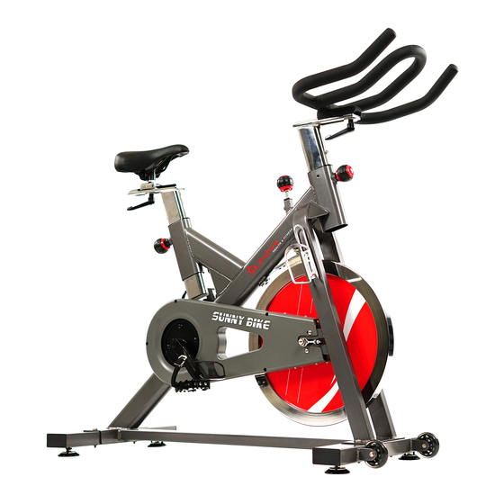
- Page 1 BELT DRIVE INDOOR CYCLING BIKE SF-B1712 USER MANUAL IMPORTANT! Read all instructions carefully before using this product. Retain owner’s manual future reference. customer service, please contact: support@sunnyhealthfitness.com...
-
Page 2: Important Safety Information
IMPORTANT SAFETY INFORMATION IMPORTANT SAFETY INFORMATION IMPORTANT SAFETY INFORMATION We thank you for choosing our We thank you for choosing our product. To ensure your safety and health, please use this product. To ensure your safety and health, please use this equipment correctly. -
Page 3: Exploded Drawing
EXPLODED DRAWING... -
Page 4: Parts List
PARTS LIST Description Description Handlebar 40L/R Pedal Handlebar post 41L/R Nylon nut 9/16*20*H8*S22 Screw M5*10*S4 42L/R Crank Washer d10*Φ40*4 Crank cap L shape knob M10*25 Nut M10*1.25*H7.5*S14 End cap Cover for middle axle Saddle post C Clip d20 Saddle column Bearing 6004-RZ Saddle Inner chain cover... -
Page 5: Hardware Package
HARDWARE PACKAGE... -
Page 6: Assembly Instructions
ASSEMBLY INSTRUCTIONS STEP 1: Remove the Shipping Tubes (No. 73) from Main Frame (No. 29) by unscrewing the 4 Screws (No. 74) and 4 Washers (No. 66) with Allen Wrench (No. A). You can save these parts for future packaging and transportation of the bike if desired. { Screws (No. - Page 7 STEP 2: Attach the Front Stabilizer (No. 68) and Rear Stabilizer (No. 63) to Main Frame (No. 29), and secure each of them together using 2 Screws (No. 67) and 2 Washers (No. 66).
- Page 8 STEP 3: A. Insert the Saddle Post (No. 7) into the Main Frame (No. 29) and fix with Knob (No. 11). B. Secure the Saddle Column (No. 8) onto the Saddle Post (No. 7) using 1 L Shape Knob (No. 5) and 1 Washer (No. 4).
- Page 9 STEP 4: Insert the Handlebar Post (No. 2) into the Main Frame (No. 29) and fix with Knob (No. 11). Secure the Handlebar (No. 1) onto the Handlebar Post (No. 2) using the 1 L Shape Knob (No. 5) and 1 Washer (No. 4).
- Page 10 52 27 28 STEP 5: Remove the 2 Screws (No. 28) and 2 Washers (No. 27) located on the Main Frame (No. 29). Then secure the Water Bottle Holder (No. 52) to the Main Frame (No. 29) using 2 Screws (No.
- Page 11 STEP 6: IMPORTANT! Read instructions carefully, failure to do so may cause permanent damage to your bike. Remove the 2 Nylon Nuts (No. 41L/R) located on the Pedals (No. 40L/R). Left Pedal: Screw the Left Pedal (No. 40L) COUNTER-CLOCKWISE into the Crank (No. 42L). Once properly screwed into the place, use the Spanner (No.
-
Page 12: Operation
OPERATION Leveling the bike This bike can be leveled to compensate for uneven surfaces. To level the bike, rotate the four leveler feet located on the underside of the front and rear stabilizers clockwise or counterclockwise until the bike is level. (Fig.1) Fig.1 Resistance Adjustment Pedaling resistance is controlled by the tension control knob... -
Page 13: Handlebar Adjustment
Handlebar Adjustment 1. Loosen and pull the pop pin (Fig.6), then raise or lower the handlebar to the desired position for a more efficient & comfortable ride. Make sure the pop pin settles into the desired hole and then secure it firmly. Fig.6 2. -
Page 14: Dismounting The Bike
Workout Once you are sitting comfortably, begin pedaling slowly, with your hands resting comfortably on the handlebar. After you feel secure, you can change seat positions, hand positions and resistance levels for added enjoyment and variety during your workout. Dismounting the bike You can stop the flywheel’s motion abruptly by pushing down the tension knob (see page 11, figure 3).
Need help?
Do you have a question about the SF-B1712 and is the answer not in the manual?
Questions and answers