
Subscribe to Our Youtube Channel
Related Manuals for Sunny SF-B1421


Summary of Contents for Sunny SF-B1421
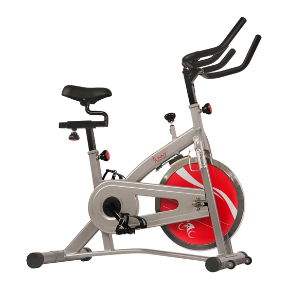
- Page 1 INDOOR CYCLING BIKE SF-B1421 USER MANUAL IMPORTANT: Read all instructions carefully before using this product. Retain owner’s manual for future reference. For customer service, please contact: support@sunnyhealthfitness.com...
-
Page 2: Important Safety Information
IMPORTANT SAFETY INFORMATION We thank you for choosing our product. To ensure your safety and health, please use this equipment correctly. It is important to read this entire manual before assembling and using the equipment. Safe and effective use can only be assured if the equipment is assembled, maintained, and used properly. -
Page 3: Exploded Drawing
EXPLODED DRAWING 1... - Page 4 EXPLODED DRAWING 2...
-
Page 5: Parts List
PARTS LIST Description Spec. Description Spec. Computer Flywheel Cover Foam Grip 23*3*480 Sensor Stopper T2*20 End Cap 25*16 Screw ST4.8*10*8 Foam grip 23*3*190 Flywheel 13*460 Handlebar Small Chain Wheel 16 teeth Handlebar Cover 125*80*42 M35*1*44*3.5 Washer D8*16*1.5 Inertia Axle 12*150*M12*1.0 Screw M8*16*S6 Knob... -
Page 6: Hardware Package
HARDWARE PACKAGE Φ... -
Page 7: Assembly Instructions
ASSEMBLY INSTRUCTIONS #8 M8*16*S6 4PCS #27 d8*Φ20*2*R30 4PCS STEP 1: Attach the Front and Rear Stabilizers (No. 26 & No. 29) to the Main Frame (No. 31) using 4 Screws (No. 8) and 4 Arc Washers (No. 27). Tighten and secure with Allen Wrench (No. - Page 8 #21 M5*16*Φ10 2pcs #20 d5*Φ10*1 2pcs STEP 2: Connect the Left & Right Pedals (No. 30L & No. 30R) to the Left & Right Crank Arms (No. 72L & No. 72R). Before you begin, immobilize the crank arms by turning the tension knob all the way to the right.
- Page 9 STEP 3: Loosen and remove the Adjustment Knob (No. 13). Insert the Handlebar Post (No. 11) into the sleeve located on the front of the Main Frame (No. 31). Adjust the Handlebar Post (No. 11) to the desired position, re-insert and tighten the Adjustment Knob (No.
- Page 10 STEP 4: Insert the link wire of the Computer (No. 1) into the middle hole of the Handlebar Cover (No. 6) as shown above in Figure I. Attach the Handlebar Cover (No. 6) to the Handlebar (No. 5) as shown above in Figure II.
-
Page 11: Exercise Computer
EXERCISE COMPUTER SPECIFICATIONS: TIME------------------------------------------- 00:00-99:59 MIN:SEC SPEED---------------------------------------- 0.0-999.9 MILES/H DISTANCE----------------------------------- 0.00-99.99 MILES CALORIES----------------------------------- 0.0-999.9 KCAL FUNCTION KEY: MODE: Press to select function. (Time, Speed, Distance, Calories.) OPERATION PROCEDURES: 1. AUTO ON/OFF: If the belt is put into motion or the mode button is pressed, the computer will activate, and remain active until its reached approximately 4 minutes of no motion. -
Page 12: Usage And Maintenance
USAGE & MAINTENANCE The SF-B1421 Indoor Cycling Bike is designed to help compensate for uneven surfaces by providing the option to level the bike! To do so, simply turn the End Caps (No. 28), located on the Rear Stabilizer (No. 29), until the bike becomes level with the ground. - Page 13 To move the bike, grab the Handlebar (No. 5) securely then push downwards until the back end of the bike comes off of the ground. Once the two front wheels located on the front stabilizer hit the ground and are put into motion, you can safely and easily move the bike to the desired location.
Need help?
Do you have a question about the SF-B1421 and is the answer not in the manual?
Questions and answers