Table of Contents
Advertisement
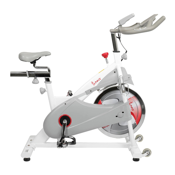
MAGNETIC BELT DRIVE PREMIUM
INDOOR CYCLING BIKE
SF-B1876
USER MANUAL
IMPORTANT! Please retain owner's manual for maintenance and adjustment instructions. Your
satisfaction is very important to us, PLEASE DO NOT RETURN UNTIL YOU HAVE CONTACTED
US: support@sunnyhealthfitness.com or 1- 877 - 90SUNNY (877-907-8669).
Advertisement
Table of Contents

Related Manuals for Sunny SF-B1876


Summary of Contents for Sunny SF-B1876
- Page 1 MAGNETIC BELT DRIVE PREMIUM INDOOR CYCLING BIKE SF-B1876 USER MANUAL IMPORTANT! Please retain owner’s manual for maintenance and adjustment instructions. Your satisfaction is very important to us, PLEASE DO NOT RETURN UNTIL YOU HAVE CONTACTED US: support@sunnyhealthfitness.com or 1- 877 - 90SUNNY (877-907-8669).
-
Page 2: Important Safety Information
IMPORTANT SAFETY INFORMATION We thank you for choosing our product. To ensure your safety and health, please use this equipment correctly. It is important to read this entire manual before assembling and using the equipment. Safe and effective use can only be achieved if the equipment is assembled, maintained, and used properly. -
Page 3: Exploded Diagram
EXPLODED DIAGRAM HARDWARE PACKAGE... -
Page 4: Parts List
PARTS LIST Description Spec. Description Spec. 20*184*43*10.5*74.5 Main Frame Middle Axle *4-10.1*105 170 “L” 9/16 Seat Post Left Crank Handlebar Belt Wheel 204*20*5PK Handlebar Post Belt 5PK1320 Adjusting Screw Screw M10*16*S6 grade 8.8 Front Stabilizer Crank Cap 25*7 Rear Stabilizer 41L/R Pedal 9/16... - Page 5 Description Spec. Description Spec. Middle Axle Cover Computer Link Wire of Plug 38*34 81a/b Computer 10*230*M8*20*M6 Handle Pulse Brake Rod *35*M10*100 Wire Left Front Side Sensor Wire Cover Right Front Side Φ17*14.5*Φ10 Magnet Cover Screw ST4.2*16*10.5 Sensor Holder Upper Flywheel Handle Pulse Cover ST4.0*19*Φ7...
- Page 6 ASSEMBLY INSTRUCTIONS We value your experience using Sunny Health and Fitness products. For assistance with parts or troubleshooting, please contact us at support@sunnyhealthfitness.com or 1-877-90SUNNY (877- 907-8669). STEP 1: Attach the Front and Rear Stabilizers (No. 6 & No. 7) to the Main Frame (No. 1) using 4 Screws (No. 9) and 4 Flat Washers (No.
- Page 7 We value your experience using Sunny Health and Fitness products. For assistance with parts or troubleshooting, please contact us at support@sunnyhealthfitness.com or 1-877-90SUNNY (877- 907-8669). STEP 3: Loosen and remove the Adjustment Knob (No. 16). Insert the Handlebar Post (No. 4) into the tube located on the front of the Main Frame (No.
-
Page 8: Battery Installation And Replacement
BATTERY INSTALLATION AND REPLACEMENT BATTERY INSTALLATION: 1. Take out 2 AAA batteries from the plastic bag for manual. 2. Press the buckle of battery cover on the back of the Computer (No. 81), then remove battery cover. 3. Install 2 AAA batteries into the battery case on the back of the Computer (No. 81). Pay attention to the battery + and –... - Page 9 ADJUSTMENTS GUIDE ADJUSTING THE BALANCE In order to achieve a smooth and comfortable ride, you must ensure that the stability of the bike is secured. If you notice that the bike is unbalanced during use, you should adjust the foot levelers located beneath the Front and Rear Stabilizers of the bike.
-
Page 10: Adjusting The Resistance
ADJUSTING THE RESISTANCE Adjust the resistance of the bike using the Tension Control Knob (No. 46). Increase the level of resistance by turning the Tension Control Knob (No. 46) to the RIGHT (clockwise), decrease the level of resistance by turning the Tension Control Knob (No. - Page 11 SPD TECHNICAL SERVICE INSTRUCTIONS Caution! Before use, read these instructions carefully. ⚫ Practice engaging and disengaging from the pedals several times in a stationary position before riding. ⚫ Before using, lubricate the concave area of the clip. ⚫ Keep the cleat and pedal clean to ensure proper usage. ⚫...
-
Page 12: Exercise Computer
EXERCISE COMPUTER FUNCTION BUTTONS MODE: Press to select the function displayed or during setting mode. Press and hold for 2 seconds to enter the RACE MODE interface during stop mode. SET: To set up the target value of TARGET, TIME, DIST, CAL. Press the button and hold for 2 seconds to speed up the increment during stop mode. - Page 13 1. TARGET: the preset CADENCE. 2. In STOP mode, press SET key to enter the TARGET setting in stop mode. Press SET to increase the CADENCE five at a time. The setting change is 15 →20→ ……110→115→120→15→20 →……→115→120→ 15 →20→ …… 3.
-
Page 14: Maintenance Instructions
MAINTENANCE INSTRUCTIONS This is general information for daily, weekly and monthly maintenance to be performed on your bike. DAILY MAINTENANCE MONTHLY MAINTENANCE After each exercise session, wipe down all the 1. Check if all hardware is secure, such as: equipment: seat, frame, and handlebars. Pay water bottle holder, flywheel nuts, belt/chain special attention to the seat post, handlebar guard bolts, brake caliper lock nuts, and...
Need help?
Do you have a question about the SF-B1876 and is the answer not in the manual?
Questions and answers