Table of Contents
Advertisement
Advertisement
Table of Contents

Related Manuals for Schiller MAGLIFE LIGHT


Summary of Contents for Schiller MAGLIFE LIGHT
- Page 1 MAGLIFE light User manual Version 1.2 / October 2006 Part No. 0-48-0080...
-
Page 2: Revision History
Note: Distribution and maintenance information SCHILLER has an international network of customer service, sales and consulting agencies. For details about your local representative, please contact the SCHILLER subsidiary near you. You will find a complete list of all the representatives and subsidiaries on our website at http://www.schiller.ch... -
Page 3: Warnings
MAGLIFE light WARNINGS This manual shall be deemed to be an integral part of the described unit. Compliance with its content is a prerequisite for proper device performance and for patients and operators safety . The manufacturer disclaims all responsibility for the safety,... - Page 4 MAGLIFE light This MAGLIFE light manual provides the information required for proper device performance. Knowledge of monitoring and the understanding of the characteristics and functions of MAGLIFE light are required for proper use of the device. Do not use the monitor before you read these instructions.
-
Page 5: Warnings, Precautions And Notes
Warning: It is imperative the MAGLIFE light be installed in the area around the magnet where the magnetic leakage field is less than or equal to 40 mT (400 Gauss) (see typical installation drawings and labels on the device). - Page 6 15°C ≤ Amb. T ≤ 35°C 60°F ≤ Amb. T ≤ 96°F Note: The instructions specific to the installation and use of the MAGLIFE light monitor have been provided in section 4 of this manual, which must be read carefully before initial use of the monitor.
-
Page 7: Table Of Contents
WARNINGS............................. 3 Foreword ..............................3 WARNINGS, PRECAUTIONS AND NOTES ..................5 Contents ..............................7 Description of MAGLIFE light .................... 8 Location and description of displays and controls ............9 Front of MAGLIFE light........................9 Rear of MAGLIFE light........................9 Mains power unit..........................9 Device symbol identification.................... -
Page 8: Description Of Maglife Light
(NIBP) MAGLIFE light may be configured with all combinations of the above parameters MAGLIFE light is fitted with batteries as standard and can move with the patient (e.g. to and from the examination room and the adjacent preparation room). -
Page 9: Location And Description Of Displays And Controls
15. USB connector 16. RS 232 connector 17. Auxiliary connector compartment cover. 18. Identification label. 2.3 Mains power unit (see photo in section 12 ) 19. Mains plug. 20. Low voltage plug for connecting the MAGLIFE light. Part number: 0-48-0080 Page 9... -
Page 10: Device Symbol Identification
MAGLIFE light 3. Device symbol identification 3.1 MAGLIFE light symbols Main device on/off key Mains power on Battery charge Entry into main menu or exit from any menu Audio alarm enable/disable Non-invasive blood pressure start/stop CF type device, is protected against defibrillation shocks (device designed for direct heart applications). -
Page 11: Use Of Maglife Light
4. Use of MAGLIFE light 4.1 Installation MAGLIFE light has been designed to operate at the patient’s bedside. It is installed in the Faraday cage, i.e. in the room with the MRI system. Minimum distances must be kept in relation to the measuring tunnel entrances. These depend on the magnetic field of the magnet and the type of magnet. - Page 12 MAGLIFE light Typical plan of an MRI system with a MAGLIFE light monitor Faraday cage MAGLIFE light monitor Mains connector Marking on the floor (40 mT line) 40 mT(400G) line Forbidden area Authorised area Figure 1 Part number: 0-48-0080 Page 12...
-
Page 13: Display Screens
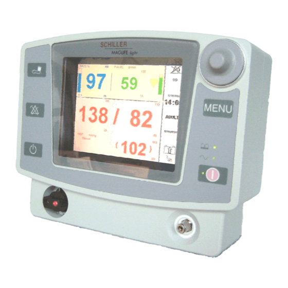
MAGLIFE light 4.2 Display screens 4.2.1 SPO option only Patient type Time Miscellaneous Date Sound alarm Battery status status Status area Quality of SPO2 signal Plethysmogram SPO2 area Pulse rate value SPO2 value Pulse area Alarm Thresholds 4.2.2 NIBP option only... -
Page 14: Spo 2 And Nibp Options
The following rules must be followed precisely to avoid the problems described below: 4.3.1 Absolute rule Use only the cables, sensors and cuffs supplied by SCHILLER. 4.3.2 Probes and sensors to be used and positioning instructions 4.3.2.1 SpO2 sensor 1. - Page 15 MAGLIFE light Warning: Remove nail polish or false nails before placing the sensor on the patient’s finger, as they could lead to inaccurate oximeter measurements. Cut long nails, as they could hinder the placing of the sensor. Warning: If the sensor is secured with tape, do not tighten the tape excessively.
-
Page 16: Sphygmomanometer Cuffs (Non-Invasive Blood Pressure)
MAGLIFE light 4.3.2.2 Sphygmomanometer cuffs (Non-Invasive Blood Pressure) 1. Make sure that the NIBP function is on and that the NIBP parameters are set correctly. 2. Connect the NIBP tube connector to the NIBP measurement connector (12). Use only the cuffs listed in section 8. -
Page 17: Start Up
The operating of key (1) is disabled during the initialisation phase. 4.5 Battery charge MAGLIFE light may be powered by the internal battery to accompany the patient as the patient is moved, or if the mains power is absent. The battery charges automatically whenever the device is connected to the mains, whether or not it is operating. -
Page 18: Use Of The Menu
MAGLIFE light 4.6 Use of the menu All the functions other than those accessible via the controls on the unit are selected from the menus displayed on the screen. You can enter the main menu in two ways: − by pressing rotary button (6) or −... -
Page 19: Nibp (Non Invasive Blood Pressure) Menu
MAGLIFE light 4.7.1.1 NIBP (Non Invasive Blood Pressure) menu Windows displayed − with the NIBP parameter disabled (select NIBP On/Off to enable) − with the NIBP parameter enabled (select NIBP On/Off to disable) • Cycle selection to select a cycle value from 1 minute to 90 minutes, activate symbol then select the appropriate value by rotating button (6) and confirm by pressing the button. - Page 20 MAGLIFE light • Patient type selection Depending on the type of patient, the initial inflating pressure is automatically selected (180mmHg for Adult/Child and 120mmHg for Neonate. Note: For subsequent measurements, the inflating pressure is automatically selected (about 50mmHg above the measured systolic pressure for Adult/Child and 30mmHg for Neonate.
- Page 21 MAGLIFE light • Use the Alarm limits button to manage thresholds. For more details, refer to section 4.7.1.3 Alarm limits and 4.9 Alarms • NIBP alarm limit setting Select a limit by rotating the navigation knob (6), press to confirm Select the limit value by rotating the navigation knob (6) again, press to confirm the selected value.
- Page 22 If required, add an inflating bulb with a deflating valve. Activate Calibration; the display on the screen will show the pressure value measured by the NIBP module. Make several comparisons between the measurements by MAGLIFE light and those by the external measuring device over the entire measurement range. Note: Calibration is regulated in some countries.
-
Page 23: Oximeter (Spo2) Submenu
MAGLIFE light 4.7.1.2 Oximeter (SpO2) submenu Windows displayed − with the SpO2 parameter disabled (select SpO2 On/Off to enable) − with the SpO2 parameter enabled (select SpO2 On/Off to disable) • Select the averaging time to be taken into account while calculating the SpO2 value and the pulse rate. - Page 24 MAGLIFE light • Use the Alarm limits tab to manage thresholds. For more details, refer to section 4.7.1.3 Alarm limits and 4.9 Alarms • SPO2 alarm limits setting Select a limit by rotating the navigation knob (6), press to confirm Select the limit value by rotating the navigation knob (6) again, press to confirm the selected value.
-
Page 25: Alarm Limits Menu
MAGLIFE light 4.7.1.3 Alarm limits menu The Alarm limits menu is used to set the thresholds for triggering alarms relating to the different parameters. Caution: The Thresholds menu only displays the thresholds for the parameters present in the configuration. Caution:... - Page 26 MAGLIFE light The Operator 1 choice gives access to the following submenu, which is used to set the thresholds from the values selected by the operator when the function was last accessed. • The Quick selection is used to set all the values in relation to the measured physiological values of the patient.
-
Page 27: Power Up And Standby Mode
MAGLIFE light Caution: Failure to monitor the condition of the patient may lead to death. • Selection Operator 2 provides access to the second set of values defined by the operator when the function was last accessed. The values can then be edited. -
Page 28: Magnetic Field Display
MAGLIFE light 4.7.1.4 Magnetic field display The B0 display button is used to display the magnetic field measurement on the screen. Values Bx, By and Bz show the value of the magnetic field in mT along the three orthogonal directions in space. The B value shows the corresponding vector modulus. -
Page 29: Trend Graph Submenu
MAGLIFE light 4.7.1.5.1 Trend graph submenu The Trend graph menu is used to select the trend curves to be displayed and contains the following tabs: Note: Only two waveforms can be shown at the same time. Navigation buttons Back one page... -
Page 30: Trend Table Submenu
MAGLIFE light 4.7.1.5.2 Trend table submenu Trend table show the numerical values of the physiological parameters according to the frequency that has been defined earlier from the trend type selection menu. The display varies according to the selected parameters Navigation buttons... -
Page 31: Edit Menu
MAGLIFE light Special displays Patient change Technical alarm Physiological alarm 4.7.1.6 Edit menu (To be written ) Part number: 0-48-0080 Page 31... -
Page 32: Settings Menu
MAGLIFE light 4.7.1.7 Settings menu The Settings menu is used to set the general parameters of MAGLIFE light and to access the demonstration mode. 4.7.1.7.1 Sound submenu The sound submenu is used to set the level of the sound for alarm signals,... -
Page 33: Clock Submenu
MAGLIFE light 4.7.1.7.2 Clock submenu The various buttons are used to set the date and time. The daylight saving option can be disabled. The clock change date is pre-set. Example of date setting. Only plausible values can be selected. Note: A time or date setting will erase all trends. -
Page 34: Device Configuration Menu
MAGLIFE light 4.7.2 Device configuration menu The configuration menus are hidden during normal operation. Access is initiated by pressing the navigation button (6) when the device is switched on and keeping it pressed until the configuration menu is displayed. Note: To exit the Device configuration mode, the device must be switched off. -
Page 35: Monitor Submenu
MAGLIFE light 4.7.2.2 Monitor submenu Note: The Language, Colour, Alarms, NIBP and Patients selection list buttons are used for settings, whilst the Serial number and Hardware number buttons are provided for information only and cannot be modified by the user. - Page 36 MAGLIFE light Button: is used for special alarm configuration. It opens the following submenu: Enabling or disabling the alarm function if the SPO drops more than 4%. A physiological alarm may be latched, i.e. confirmation by pressing key (9) is required to stop it, even when the value of the parameter has exceeded the threshold and is back in the non-alarm range.
-
Page 37: Options Submenu
Note: The procedure has been described in detail in the Service Manual of the device. For more information, please contact the technical service network of Schiller Medical. Part number: 0-48-0080 Page 37... -
Page 38: Version Submenu
MAGLIFE light 4.7.2.5 Version submenu The Version tab will show detailed info about used software versions and releases in MAGLIFE light 4.7.2.6 Reserved SCHILLER submenu This submenu is only for technical purpose and is described in a separate manual. Part number: 0-48-0080... -
Page 39: Structure Of Menus
MAGLIFE light 4.8 Structure of menus 4.8.1 User menus Part number: 0-48-0080 Page 39... - Page 40 MAGLIFE light Part number: 0-48-0080 Page 40...
-
Page 41: Configuration Menus
MAGLIFE light 4.8.2 Configuration Menus Same for Child Same for Adult Part number: 0-48-0080 Page 41... -
Page 42: Alarms
MAGLIFE light 4.9 Alarms 4.9.1 Screen alarm symbols Audible alarms enabled Alarm sound disabled! Displayed when at least one monitoring threshold is disabled. Technical alarms will go off all the same. Alarm sound disabled for 2 minutes. Displayed when you press key (9) (for less than three seconds). -
Page 43: Technical Alarms
MAGLIFE light 4.9.3 Technical alarms When a technical alarm is triggered: • an error message is displayed in the display field of the parameter in question • an intermittent audible alarm goes off (sequence of two audible signals that is repeated); it depends on the audible alarm configuration criteria •... -
Page 44: Technical Specifications Of Modules
MAGLIFE light Display Colour TFT screen: 6.8”; 98 x 132mm; 480 x 640 dots Connections and NIBP Interfaces RS232, USB 1.1 for connecting the equipment specified by SCHILLER Safety standards IEC 60601-1 IEC 60601-1-2 CISPER 11 Class B; with printer connected, class A... -
Page 45: Threshold Ranges
MAGLIFE light Types of patient Neonate, Child, Adult ± 3mmHg or ± 2 % Sensor accuracy Pulse accuracy 5 b/min Display range Adult / Child: systolic: 30 - 255 mmHg diastolic: 15 - 220 mmHg mean: 20 - 235 mmHg... -
Page 46: Cleaning
The use of an autoclave is not permitted. The device and its accessories need to be decontaminated (risk of pathological contamination) before disposal. The batteries of MAGLIFE light must be disposed of using a special procedure and not merely scrapped. Part number: 0-48-0080... -
Page 47: Troubleshooting
MAGLIFE light 7. Troubleshooting 7.1 General errors Error Cause Remedy • • Mains not connected Check and correct the connections - LED (3) must be on • • The screen does not activate Battery discharged Connect the mains - LED... -
Page 48: Errors Of Modules
MAGLIFE light 7.2 Errors of modules Error Cause Remedy • • Optical probe faulty Replace the probe • • Ambient light artefacts Cover the sensor holder on the finger • • No perfusion Change the signal taking No SPO2 measurement location •... -
Page 49: Additional Accessories And Indications
MAGLIFE light 9. Additional accessories and indications MAGMOVE light Amagnetic trolley with storage basket for MAGLIFE light 0-13-0010 Adult finger SpO sensor, 5.2 m - fibre optic 0-13-0011 Child finger SpO2 sensor, 5.2 m - fibre optic 0-13-0012 Universal Y SpO2 sensor, 5.2 m - fibre optic 0-13-0008 Adult finger SpO2 sensor, 4.2 m - fibre optic... -
Page 50: Front
11. Front Part number: 0-48-0080 Page 50... -
Page 51: Rear And Power Supply
12. Rear and power supply Part number: 0-48-0080 Page 51...
Need help?
Do you have a question about the MAGLIFE LIGHT and is the answer not in the manual?
Questions and answers