
Related Manuals for Viadrus A3W


Summary of Contents for Viadrus A3W
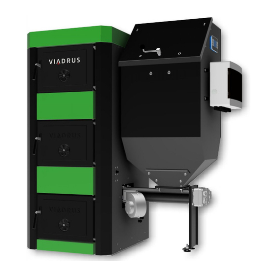
- Page 1 VIADRUS A3W Manual for boiler operation and installation GB_2017_2_S25X GB_2015_47...
-
Page 2: Table Of Contents
Content: Boiler Use and Advantages ........................... 3 Technical parameters of the boiler ........................4 Description ................................9 Boiler Construction ............................9 Location and installation ............................10 Regulations and guidelines .......................... 10 Placement options ............................11 Hydraulic connection diagram ........................13 Boiler installation .............................. -
Page 3: Boiler Use And Advantages
Dear Customer, Thank you for purchasing an automatic solid fuel fired boiler VIADRUS A3W and thus showing your confidence in the company VIADRUS a.s. For the correct way of handling your new boiler, please read the instructions for its use (especially the Chap. 6 –... -
Page 4: Technical Parameters Of The Boiler
Technical parameters of the boiler Tab. №. 1 Dimensions and technical parameters of the boiler Weight of the boiler with a small tank Weight of the boiler with a large tank Water content Flue socket diameter Fuel tank capacity – small Fuel tank capacity –... - Page 5 ! Important warning: The stated thermal technical parameters vary in dependence on the sort, quality and moisture of the used fuel. Therefore some corrections might be necessary when setting the stoking cycle (time for fuel feed versus time for fuel afterburning). For example if unburned fuel slivers appear on the grate and in the ash- pan it stands to reason that stoking is faster than burning and the stoking cycle must be reduced –...
- Page 6 Fig. №. 2 Main dimensions of the boiler (right-hand version) (dimensions after the slash apply to the version with a large tank)
- Page 7 VIADRUS A3W S25P Cogeneration solid fuel Condensing boiler Combined boiler fired boiler Preferred fuel Fuel Other suitable fuel: (only one type): Wood logs, the moisture content ≤ 25% Wood chips, moisture content 15 - 35% Wood chips, moisture content > 35 % Pressed wood in the form of pellets or briquettes Sawdust, moisture content of ≤...
- Page 8 VIADRUS A3W S25B Cogeneration solid fuel Condensing boiler Combined boiler fired boiler Preferred fuel Fuel Other suitable fuel: (only one type): Wood logs, the moisture content ≤ 25% Wood chips, moisture content 15 - 35% Wood chips, moisture content > 35 % Pressed wood in the form of pellets or briquettes Sawdust, moisture content of ≤...
-
Page 9: Description
Description Boiler Construction 1. Boiler drum 2. Cleaning door 3. Burner with grate 4. Fuel feeder with the electric motor 5. Switchboard 6. Fuel tank 7. Return water flange 8. Heating water flange 9. Shell 10. Thermostat well 11. Cleaning door Fig. -
Page 10: Location And Installation
Location and installation Regulations and guidelines Boiler meets the following standards: EN ISO 12100:2011 Safety of machinery - General principles for design - Risk assessment and risk reduction EN 953+A1:2009 Safety of machinery - Protective covers - General requirements for the design and construction of fixed and movable protective covers CSN ISO 1819:1993 Equipment for continuous transport of cargo. -
Page 11: Placement Options
e) to the power supply network CSN 33 0165 Electrical regulations. Identification of conductors by colours or numerals. Procedure provisions CSN 33 1500 Electrical regulations. Revision of electrical equipments. CSN 33 2000-1 ed. 2 Low-voltage electrical installations – Part 1: Fundamental principles, assessment of general characteristics, definitions. - Page 12 Continuous air supply for burning and eventual ventilation must be provided into the room where the boiler is installed (the air consumption of the boiler VIADRUS A3W is about 75 m ). Connection of the heating system piping or the heating element heater piping must be performed by authorized personnel.
-
Page 13: Hydraulic Connection Diagram
Fig. №. 6 The boiler VIADRUS A3W ((right-hand design with the small tank) with open fuel tank Hydraulic connection diagram Combined storage water heater El. heating controlled separately Three-way ball valve SIEMENS min. DN 25 with reversible actuator - 2-point control (do not use the actuator with return spring) For larger heating system it is suitable to use an alternative connection to the heating circuit, as with the variant Z1. - Page 14 Fig. №. 8 Hydraulic diagram without HW preparation – pump heating circuit Key of piping, signs and symbols in the diagrams:: If the reversible (and intake) pipe is led from the boiler upward, it may cause unwanted circulation of water in one pipe.
-
Page 15: Boiler Installation
Boiler installation Delivery and accessories The boiler is supplied according to the order so that the complete boiler drum including the basement is placed on the palette. The boiler shell is packed separately. Accessories are stored inside the boiler drum, accessible by opening the cleaning door. - Page 16 • Safety valve (1 pc) according to the maximum boiler operating overpressure (see tab. no. 1) • Water heater (according to VIADRUS a.s. offer) Obligatory accessories for the pump heating circuit (not included to the delivery): • Circulating pump Grundfos UPS 25-40 •...
-
Page 17: Installation Procedure
Installation procedure Fig. №. 9 Connecting dimensions of the boiler 5.2.1 Installation of the boiler drum with the basement Position the boiler drum with the basement on the substructure (pad) at the horizontal position. Connect the heating water outlet and the heating system. Connect the return water outlet and the heating system. - Page 18 Ash-pan Ash rectifier Grate Air inlet pipe Fireclay top plate Lower ceramics Turbulators Fig. №. 11 Placement of components and ceramics inside the boiler...
-
Page 19: Shell Installation
5.2.2 Shell installation Boiler drum 13. Front cover (2 pc) Right shell 14. Rear insulation Right isolation 15. Rear cover Left shell 16. Rear insulation cover Left isolation 17. Safety thermostat holder Cover of the break-out opening 18. Upper cover Screw ST 4.8 x 13 (20 pc) 19. -
Page 20: Fuel Tank Mounting
5.2.3 Fuel tank mounting Fuel feeder Screw M8 x 20 (4 pc) Stud M10 x 30 (4 pc) Nut M8 (4 pc) Washer 10.5 (4 pc) 10. Washer 8.4 (8 pc) Nut M10 11. Adjustable foot 12. Sealing under the tank Screw M6 x 16 (4 pc) Fuel tank Fig. -
Page 21: Switchboard Mounting To The Fuel Tank
5.2.4 Switchboard mounting to the fuel tank Switchboard Screw M6 x 16 (4 pc) Mudguard washer 6.4 (4 pc) Flexible washer 6.4 (4 pc) Nut M6 (4 pc) Fig. №. 14 Switchboard mounting to the fuel tank Screw the switchboard to the fuel tank side. Perform wiring according to the diagrams in Chap. -
Page 22: Boiler Conversion From Right-Hand Design To The Left-Hand Design
Cleaning hole cover Sensor holder Fig. №. 15 Mounting of emergency fire-extinguishing equipment 5.2.7 Boiler conversion from right-hand design to the left-hand design − Remove the grate and pull out the burner with the mixer from the boiler dram (fixtures are as follows: 6 pc screw M10 x 30, 6 pc washer 10.5). - Page 23 Apply a reasonable amount of new sealant to the flange seating surface. Connect the fuel feeder with the fuel tank (fixtures are as follows: 4 pc screw M8 x 25, 4 pc washer 8.4 and 4 pc nut M8). Connect the emergency fire-extinguishing equipment. Connect the switchboard incl.
- Page 24 Screw M10 x 30 (6 pc) Insulation of the opening (sibral mat) Washer 10.5 (16 pc) Fig. №. 18 Boiler conversion from the right-hand to left-hand design – disassembly of the burner and the blind flange Fig. №. 19 Kotel VIADRUS A3W (left-hand design)
-
Page 25: Electrical Wiring Diagram
5.2.8 Electrical wiring diagram Display connection POL 871.71/STD Fig. №. 20 Climatix POL 423.50 circuit diagram... - Page 26 Fig. №. 21 Climatix POL 423.50 wiring diagram...
- Page 27 Fig. №. 22 Schéma zapojení Climatix POL 423.50...
- Page 28 Display connection POL 871.71/STD Fig. №. 23 Obvodové schéma zapojení Climatix POL 687...
- Page 29 Fig. №. 24 Schéma zapojení Climatix POL 687...
- Page 30 Fig. №. 25 Schéma zapojení Climatix POL 687...
-
Page 31: Boiler Operation By User
Boiler operation by user Control, regulation and safety elements 6.1.1 Climatix control unit Heating - automatic mode The boiler must be in the ON mode (display of the Climatix control unit ). Heating demand is generated by closing an external control. External control is a potential-free switch contact to which the room thermostat (D1) can be connected at heating to the boiler temperature. -
Page 32: Safety Thermostat
Setback mode If there is no demand for heating or hot water, the boiler is in setback mode. This mode is indicated by the green LED flashing on the boiler display. In this mode, the minimal boiler temperature is maintained only by the min. fan power without the pump operation (factory setting 65 °C). -
Page 33: Pol 871 Control Unit To The Climatix Control Unit
Placement and connection to the Climatix control unit Placement Appropriate placement of the control unit is on the front or side of the fuel tank of the boiler VIADRUS A3W. Part of the control unit is a magnet in its rear part. -
Page 34: Description Of The Parameters
Description of the parameters Note: The control unit is used for several types of the VIADRUS boilers, therefore, displays the settings (e.g. fuel type), which are not intended for this type of the boiler. Through the menu (start page) and other sub-menus, the names of the parameters or directly the setting lines can be accessed. - Page 35 Description Range VIADRUS 1/12 18.02.14 13:51 Boiler status On/Off Boiler Status Shut-down Shut-down/ Operation/Setback operation/External setback/Setback from temperature/ Firing/Out of operation ► Power ► 0s/0s Fuel feeding ► B2 Boiler temperature 21°C B8 Exh. gas temperature 22°C ► Fuel Lignite Lignite ►...
- Page 36 Description Settings Range User menu ► Manual control ► Spotreba paliva ► Par. for reduce ► Provozni hodiny ► Status of binary inputs ► Status of binary outputs ► Status of analog inputs ► Status of analog outputs ► Diagnostic of source ►...
- Page 37 Description Settings Range 5.4.1 Reset hours run ActRunTime 0.0h 0.0 ÷ 250000.0h ActReduceTime 0.0h 0.0 ÷ 250000.0h Boiler pump 0.0h 0.0 ÷ 250000.0h Feeder 1 0.0h 0.0 ÷ 250000.0h Description Display Status of binary inputs External on Safety termostat Backfire sensor Termocontact feeder Description Display...
- Page 38 Description Display 5.11.1 sVersions BSP version 10.2 Application info - 1.2.2016 1.0 - A3W (Boiler type) - POL 423 Description Display Range 5.11.2 sSave/load █/Execute Set appli.default Description Setting Range 1/21 5.12 sTCP/IP DHCP Passive Passive/Active Actual IP 192.168.001.042 Actual Mask 255.255.255.000...
-
Page 39: Malfunctions
6.2.4 Malfunctions ATTENTION! At the extremely clogged heat exchanger, flue gas temperature will increase. If it reaches 300 °C (factory setting), the boiler output will be reduced. We recommend regular cleaning of the boiler see Chap. 7. The fault is signalled by the red LED flashing on the button B and the red LED shining on the button A. When pressing the button B, the list of failures is displayed. -
Page 40: Verification Activities Before The Boiler Commissioning
Verification activities before the boiler commissioning Putting into operation can be performed only by a contractual service company authorized to carry out this activity. Before the boiler commissioning it is necessary to check: a) filling the heating system with water Water for filling the boiler and heating system must be clear and colourless, without suspended solids, oil and aggressive chemicals. -
Page 41: Parameters Setting Before The Equipment Start-Up
Parameters setting before the equipment start-up Parameters necessary for the equipment start-up Before performing the first ignition, it is necessary to adjust the Year, Date, Time for the proper function of the HW preparing time schedules if the HW time schedule is active. Check the parameters of the factory settings according to the Tab. -
Page 42: Operation - Liginite
Operation - liginite Check of shape of the flame. The shape of flame provides information about the correct setting of the boiler at the rated output. It is recommended to check it with each purchase of new coal: By means of the fan parameter, adjust the amount of required air so as the shape of the flame matches Fig. 25. This amount is dependent on the performance and quality of the fuel. -
Page 43: Instructions For The Product Disposal After Its Useful Life Period
Instructions for the product disposal after its useful life period VIADRUS a.s. is the contract partner of the company EKO-KOM a.s. with the client number F00120649. The packaging complies with EN 13427. The packaging should be disposed of as follows:... -
Page 44: Warranty And Liability For Defects
In particular, it is necessary to specify when and by whom the boiler was put into operation and the precise address of the boiler operation. VIADRUS a.s. provides an extended warranty on the boiler drum for a period of 36 months from the date of purchase, max. 42 months from date of shipment from the factory. - Page 45 Information for customer Packaging identification Assessment reference PE Plastic sacks, folie, corrugated board, iron and plastic fix line Identification of principal materials used. Paper, Polyethylene, iron, wood Part 1: Summary of assessment Standard/Report Assessment requirement Claim Note 1.1 Prevention by source reduction 1.2 Heavy metals and ensure below maximum permitted levels...
- Page 47 Annex to the warranty card for the customer – the user Record of warranty and after-warranty repairs and checks performed on the product Contractual service Customer Record date Performed activity organization signature (signature, stamp)
- Page 48 VIADRUS A3W VIADRUS a.s. Bezručova 300 | CZ - 735 81 | Bohumín E-mail : info@viadrus.cz | www.viadrus.cz...
Need help?
Do you have a question about the A3W and is the answer not in the manual?
Questions and answers