
Related Manuals for Inflight Fitness VANGUARD


Summary of Contents for Inflight Fitness VANGUARD
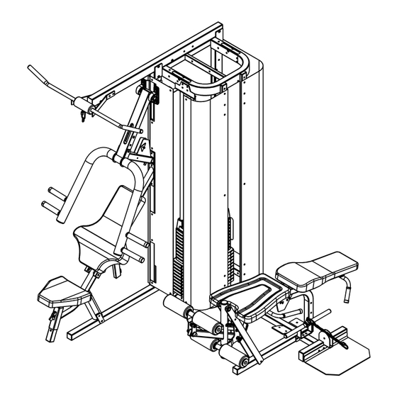
- Page 1 VANGUARD with LEG PRESS OPTION ASSEMBLY MANUAL...
- Page 2 Should there be any question during assembly contact your authorized Inflight Fitness dealer or call direct to 714 821 4177. The Vanguard 2 –stack may be assembled two ways to provide a more enjoyable exercise experience. See the cover for views. For instance, do not block access to the leg station by putting the leg extension/leg curl side of the machine in a corner.
- Page 3 VANGUARD PARTS AND HARDWARE VANGUARD PARTS AND HARDWARE PARTS HARDWARE PLATINUM FRAME PARTS DESCRIPTION QUANTITY Main Upright Base Tube Mid-Frame Bolts Base Frame MEC Lower Attach Top Beam 3/8” x 4 ½” Top Frame Vertical Tubes (2) Low Row Tube 3/8”...
- Page 4 VANGUARD ASSEMBLY INSTRUCTIONS MAIN STRUCTURE ASSEMBLY A1. Assemble the Base Frame to the Main Upright and Base tube using 2 – 3/8” x 3” bolts, 2 – 3/8” x 2 ¾” bolts, 8 – 3/8” flat washers and 4 – 3/8” nuts. Do not fully tighten the bolts at this time.
- Page 5 VANGUARD ASSEMBLY INSTRUCTIONS Top Beam 1 - 3/8" x 3" Bolt Top Frame MAIN STRUCTURE ASSEMBLY 2 - 3/8" x 2 3/4" Bolt 2 - 3/8" x 3" Bolts 6 - Washers 4 - Washers 3 - Nuts 2 - Nuts B1.
- Page 6 VANGUARD ASSEMBLY INSTRUCTIONS WEIGHT STACK INSTALLATION 2 - Guide Rods 2 - Weight Cushions 10 - 10lb. Weight Plates C1. Insert 2 - Guide Rods into the two large holes in the Mid Frame near the center of 10 - 5lb. Weight Plates the machine.
- Page 7 VANGUARD ASSEMBLY INSTRUCTIONS STATION STRUCTURE ASSEMBLY 2 - Bearing Brackets 2 - 3/8" x 3" Bolts D1. Attach the two Bearing Flats to the Main MEC Frame using 2 – 3/8” x 4 ½” bolts, 4 – 4 - Washers ½”...
- Page 8 VANGUARD ASSEMBLY INSTRUCTIONS MPS/MLA STATION CABLE ASSEMBLY 1 - 4 1/2" Pulley 1 - 1/2" Step Spacer 1 - 3/4" Step Spacer E1. The Press Arm and Pillow Block Bearings attach to the Bearing Brackets using 4 – 1 - 3/8" x 2 3/4" Bolt 3/8”...
- Page 9 VANGUARD ASSEMBLY INSTRUCTIONS MPS/MLA STATION CABLE ASSEMBLY (CONTINUED) 1 - 6" Pulley 1 - 3/8" x 3" Bolt 1 - Cable Retainer 2 - Washers 1 - 3/8" x 2 3/4" Bolt 1 - Nut F1. Thread the P13-0452 cable into the threaded boss in the Top Weight. Remember...
- Page 10 VANGUARD ASSEMBLY INSTRUCTIONS 1 - Double Pulley Bracket 1 - 6" Pulley MEC/LOW ROW STATION CABLE ASSEMBLY 1 - 4 1/2" Pulleys 1 - Angle Cable Retainer 1 - 3/8" x 2" Bolts 1 - 3/8" x 2 3/4" Bolt...
- Page 11 VANGUARD ASSEMBLY INSTRUCTIONS PAD AND PAD SUPPORT ASSEMBLY 1 - Back/Thigh Pad 3 - 3/8" x 3" Bolts H1. Attach the two Seat Handles to the MEC Frame using 2 – 3/8” x 3” bolts, 2 – 3/8” with blue patch washers and 1 –...
- Page 12 VANGUARD ASSEMBLY INSTRUCTIONS SHROUD ASSEMBLY 1 - Flat Shroud* 10 - 1" Spacers* 8 - 1/4" x 1 3/4" Screws* NOTE: If you are not installing shrouds proceed to Step K2 on pages 22 and 23. Then 1 - Angle Shroud Bracket* 10 - 1/4"...
- Page 13 VANGUARD ASSEMBLY INSTRUCTIONS Note: Slot position for opposite build is at bottom. SHROUD ASSEMBLY CONTINUED Remove extra screws Note: Slot position for opposite before installing shroud build is at bottom. Remove extra screws NOTE: If you are not installing shrouds proceed to Step K2. Then proceed to pages before installing shroud 26 and 27 for placard installation.
- Page 14 VANGUARD ASSEMBLY INSTRUCTIONS 1 - Small Curved Shroud* 1 - Small Curved Shroud* 7 - 1/4" x 3/4" Screws(2*) SHROUD ASSEMBLY CONTINUED 7 - 1/4" x 3/4" Screws(2*) 7 - 1/4" Washers(2*) 7 - 1/4" Washers(2*) 2 - 3/8" x 1 3/4" Bolts*...
- Page 15 VANGUARD ASSEMBLY INSTRUCTIONS 1 - LH Lat Bar Holder PLACARD AND ACCESSORY ASSEMBLY Multi Press/Lat Placard 1 - RH Lat Bar Holder 2 - 3/8" x 3" Bolts M1. Attach the L/H and R/H Lat Bar Holders using 2 – 3/8” x 3” Bolts, 4 – 3/8” Washers 4 - Washers and 2 –...
- Page 16 VANGUARD ASSEMBLY INSTRUCTIONS CABLE TENSION ADJUSTMENT USE CAM WASHER TO N1. Adjust the cable tension on the MEC station by loosening the jam nut on the ADJUST CABLE TENSION threaded stop behind the MEC exercise arm and threading the stop in or out. Re- USE THREADED STOP TO tighten the jam nut.
Need help?
Do you have a question about the VANGUARD and is the answer not in the manual?
Questions and answers