Table of Contents
Advertisement
Advertisement
Table of Contents

Related Manuals for Wincor Nixdorf BA63


Summary of Contents for Wincor Nixdorf BA63
- Page 1 BA63 Customer Display Product Manual Edition March 2003...
- Page 2 MS-DOS™, Windows 95™, Windows 98™, Windows NT™ and Windows CE™ are registered trademarks of the Microsoft Corporation BEETLE™ is a registered trademark of Wincor Nixdorf International GmbH Copyright© Wincor Nixdorf International GmbH, 2003 The reproduction, transmission or use of this document or its contents is not permitted without express authority.
-
Page 3: Table Of Contents
Contents Manufacturer’s Declaration and Approval ......1 FCC-Class A Declaration ................1 Notes on Care .....................2 Warranty ......................2 Recycling the BA63 ..................3 General Notes ..............4 Installation of the Connector ..........6 Tube-based ....................6 Base/ Rotating Plate..................8 Customer Display Control ..........11 Control Sequences ............12 Backspace (without deleting) ..............12... -
Page 4: Manufacturer's Declaration And Approval
Règlement sur le brouillage radioélectrique édicté par le ministère des Communications du Canada. Wincor Nixdorf International GmbH (WN) accepts no responsibility for radio and television reception interference resulting from unauthorized modifications to the equipment. Furthermore, neither cables nor devices which have not been approved for use by WN may be connected. -
Page 5: Notes On Care
Warranty Wincor Nixdorf guarantees a limited warranty engagement for 12 months beginning with the date of delivery. This warranty engagement covers all those damages which occur despite a normal use of the product. -
Page 6: Recycling The Ba63
Recycling Center, which is certified pursuant to ISO 9001. So don’t simply throw your BA63 on the scrap heap when it has served its time, but take advantage of the environmentally smart, up-to-date recycling... -
Page 7: General Notes
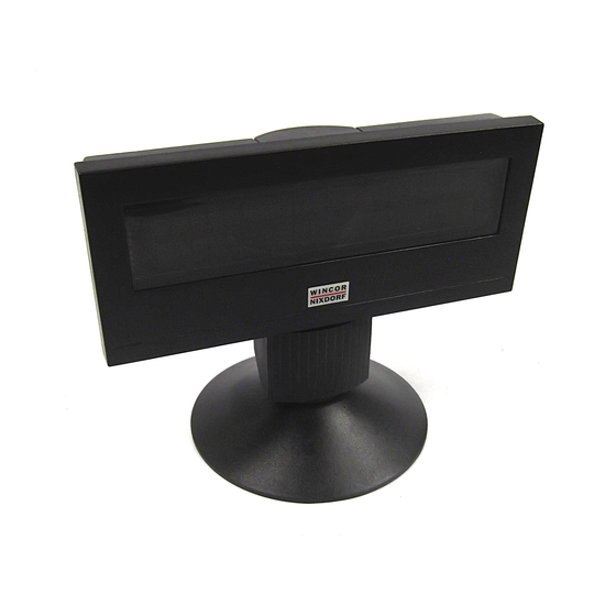
GENERAL NOTES General Notes The BA63 customer display is mainly used in POS installations which are designed in modular form. It is either securely screwed to the POS keyboard or installed near it so that it is ideally positioned in the cashier’s field of vision. - Page 8 GENERAL NOTES Customer display with adaptor for tube-based installation...
-
Page 9: Installation Of The Connector
TUBE-BASED Installation of the Connector Tube-based Press the release knob marked with the arrow in the drawing (1) and ‚ disconnect the hinge from the customer display (2). Thread the cable through the adapter (3) and then through the hinge (4). - Page 10 TUBE-BASED Connect the hinge and adapter. Secure the connector cable in the strain relief. The distance between the strain relief and the tip of the connector must be 66 mm (± 4 mm). 66 mm +/- 4 mm...
-
Page 11: Base/ Rotating Plate
BASE/ ROTATING PLATE Plug the cable connector into the appropriate socket of the customer display and plug the adapter/hinge into the customer display again until it locks into place. Base/ Rotating Plate Press the release knob marked with the arrow in the drawing (1) and disconnect the hinge from the ‚... - Page 12 BASE/ ROTATING PLATE Thread the cable through the base (3) and then through the hinge (4). „ ƒ Connect the base and the hinge.
- Page 13 BASE/ ROTATING PLATE Plug the cable connector into the appropriate socket of the customer display and plug the base/hinge into the customer display again until it locks into place. A metal bracket of the strain relief is situated on the bottom side of the base table.
-
Page 14: Customer Display Control
CUSTOMER DISPLAY CONTROL Customer Display Control The customer display is controlled via software. The commands are entered with the appropriate ESC sequences. The following functions are available: The cursor can be moved to the desired position; The customer display can be deleted; The characters from the cursor to the end of the line can be deleted;... -
Page 15: Control Sequences
CONTROL SEQUENCES Control Sequences The customer display operates in VT100 mode, i.e. it emulates a subset of the VT100 ESC sequences and control bytes. These are illustrated in the following: Backspace (without deleting) Line feed Carriage return Delete display ESC [2J Position cursor ESC [Py;PxH Delete to end of line... -
Page 16: Carriage Return
CONTROL SEQUENCES Carriage return The cursor is moved to the start of the line in which it is currently positioned when the CR command (hexadecimal 0D) is entered. The command is ignored if the cursor is already at the start of the line. Delete display The display can be deleted with this ESC sequence. -
Page 17: Delete To End Of Line
CONTROL SEQUENCES ESC ‘[‘ ‘1’; ‘1’ ‘H’ If you select 0 for the parameter value, this is interpreted as 1 by the display. If, on the other hand, you select a value which is greater than the maximum line and column value, the display will interpret this value as the maximum value permissible. - Page 18 CONTROL SEQUENCES Country code Character set France Germany Great Britain Denmark 1 Sweden Italy Spain 1 Japan Norway Denmark 2 Spain 2 Latin-America Furthermore PC code pages which contain additional country-specific display codes can be selected by ESC R n with the following codes: Country Code page Character set...
-
Page 19: Call Display Identification
Latin/Greek 2 Greece Katakana Katakana Japan In the appendix there are shown all character set tables for BA63 in 5 x 7 matrix display. Call display identification The identification is called with the following ESC sequence: ‘[‘ ‘1’; ‘1’ ‘H’... -
Page 20: System Connection
SYSTEM CONNECTION System Connection The system is connected via the RS232C (V.24) interface with a voltage supply of +12V DC. The following parameters are set as standard: Transmission rate 9.600 Bit/s Parity Parity Parameters other than these standard values can also be selected. Wire jumpers must be soldered onto the display circuitry in order to do so. - Page 21 SYSTEM CONNECTION exterior housing clips underneath the plate. The wire jumpers are then accessible. JP5 JP4 JP3 JP2 JP1 Customer display circuitry...
-
Page 22: Cable Connection
CABLE CONNECTION Cable Connection The customer display cable features a mini DIN connector at one end (which is connected to the customer display) and a 9-pin D sub connector at the other (which is connected to the COM interface of the point of sale system). -
Page 23: Test Functions
TEST FUNCTIONS Test Functions The internal RAM of the processor and the EPROM are tested during the start-up phase. All display elements light up for approx. 0.5 seconds if no errors are detected during the test. The display remains blank if an error is isolated. -
Page 24: Technical Data
TECHNICAL DATA Technical Data The technical data of the BA63 customer display is detailed in the following table: Vacuum Fluoreszenz Display (VFD) Display technology 2 lines each with 20 alphanumeric characters Matrix: 5 x 7 pixel Height: 9.5 mm Character display Width: 6.2 mm... - Page 25 Herausgegeben von/ Published by Wincor Nixdorf International GmbH D-33094 Paderborn, D-13629 Berlin 0175 0000 179G Bestell-Nr./ Order No.: Printed in Singapore...
Need help?
Do you have a question about the BA63 and is the answer not in the manual?
Questions and answers