Table of Contents
Advertisement
Quick Links
Advertisement
Table of Contents

Related Manuals for Wincor Nixdorf Beetle/XL-I


Summary of Contents for Wincor Nixdorf Beetle/XL-I
- Page 1 BEETLE /XL-II Modular POS System User Guide Edi ti on April 2005...
- Page 2 Li nux™ is a re gis te red tra de mark of Li nus Tor valds Pen ti um™ is a re gis te red tra de mark of the In tel Cor po ra ti on MS-DOS™, Wind ows 95™, Wind ows 98™, Wind ows NT™, Wind ows CE™, Wind ows2000™and Wind ows XP™...
-
Page 3: Table Of Contents
Contents Ma nu fac tu rers Cer ti fi ca ti on ..........1 Tes ted Sa fe ty....................1 FCC-Class A De cla ra ti on................1 Im por tant No tes ..................2 Note on the la ser ..................3 In tro duc ti on................4 About this Ma nu al ..................4 Care of the BEET LE /XL-II................5 Re cy cling the BEET LE /XL-II ..............6... - Page 4 Mo du lar Prin ters ..................22 Cash Dra wer (1,2) ................23 BEET LE /XL-II - the Com po nents ........24 Over view....................24 Flop py Disk Dri ve..................26 Ge ne ral ....................26 Re mo ving a Disk .................27 CD-ROM Dri ve..................27 Ge ne ral ....................27 Ope ra ting the Dri ve ................28 No tes....................29...
-
Page 5: Manufacturers Certification
TESTED SAFETY Manufacturers Certification The device complies with the requirements of the EEC directive 89/336/EEC with regard to ‘Electromagnetic compatibility" and 73/23/EEC “Low Voltage Directive”. Therefore, you will find the CE mark on the device or packaging. Tested Safety The POS sys tem has been pro vi ded with the sym bol for “Tes ted Sa fe ty”. -
Page 6: Important Notes
Customer Service of Wincor Nixdorf or your dealer must be notified. The device may only be repaired by authorized qualified personnel. -
Page 7: Note On The Laser
NOTE ON THE LASER Your BEETLE POS system is the result of modern technical innovation. So please see for according structural and technical surroundings to guarantee a faultless and efficient work of your BEETLE. Therefore, you should connect your BEETLE or other IT-devices only to power supply systems with separately guided protective earth conductor (PE). -
Page 8: Introduction
The BEETLE can also be connected to a network once an appropriate network card has been installed. Whatever configuration you need: Wincor Nixdorf offers the right solution. So, whenever you want to expand your BEETLE /XL-II, please contact your Wincor Nixdorf branch office or your dealer. -
Page 9: Care Of The Beetle /Xl-Ii
CARE OF THE BEETLE /XL-II The fourth section provides a general overview of the Wincor Nixdorf Retail Software. Section five explains the start and runup behaviour of the BEETLE /XL-II. The Appendix con tains the most im por tant tech ni cal data, a glos sa ry and a list of ab bre via tions. -
Page 10: Recycling The Beetle /Xl-Ii
RECYCLING THE BEETLE /XL-II Recycling the BEETLE /XL-II En vi ron men tal pro tec ti on does not be gin when the time has come to dis po se of the BEET LE; it be gins with the ma nu fac tu rer. This pro duct was de sig ned ac cor ding to our in ter nal norm “En vi ron men tal cons ci ous pro duct de sign and de ve lop ment”. -
Page 11: Warranty
WARRANTY Warranty Win cor Nix dorf gua ran tees ge ne ral ly a war ran ty en ga ge ment for 12 months be gin ning with the date of de li very. This war ran ty en ga ge ment co vers all tho se da ma ges which oc cur de spi te a nor mal use of the pro duct. -
Page 12: Beetle /Xl-Ii
OVERVIEW BEETLE /XL-II Overview You can connect a variety of peripherals to your modular POS system BEETLE /XL-II and thus implement a wide range of expansion stages. You can connect a two or four-line alphanumeric customer display and a four line cashier display. -
Page 13: Beet Le /Xl-Ii Pe Ri Phe Rals
OVERVIEW BEET LE /XL-II Pe ri phe rals BA72 SNIkey MO34 BA63 EL44 KA18 TH210 TA58 EL30... -
Page 14: Beet Le /Xl-Ii In A Net Work
OVERVIEW BEET LE /XL-II in a Net work Server Ethernet 10/100 Base T... -
Page 15: Before Switching On The System
If damage has occurred during shipping or if the package contents do not match the delivery note, promptly inform your Wincor Nixdorf sales outlet. Trans port the de vi ce only in its ori gi nal pa cka ging (to pro tect it against im pact and shock). -
Page 16: Con Nec Ting To The Mains Po Wer Supp Ly
BEFORE SWITCHING ON THE SYSTEM Con nec ting to the Mains Po wer Supp ly All devices belonging to the modular BEETLE /XL-II system that have a separate power cable must be connected to the same electric circuit. Make sure that all data cables on the system unit and peripherals are connected correctly. -
Page 17: Moun Ting An Ex Haust Air Hood
BEFORE SWITCHING ON THE SYSTEM The D-sub type connector or CRT (VGA) connector is used for parallel or serial interfaces. Release the connector by loosening the two screws. Take hold of the USB connector housing and release the connection. Loosen the plug of the USB powered connector by pressing the metal latch. - Page 18 BEFORE SWITCHING ON THE SYSTEM Recess Recess Ex haust Air Hood Put the BEETLE upright onto the left side (i.e. the side with three ventilation areas). Attach the Exhaust Air Hood to the BEETLE: Push the recesses on the left and right hand side of the hood to the rubber base of the BEETLE.
-
Page 19: Installation Of The Beetle /Xl-Ii
INSTALLATION OF THE BEETLE /XL-II Installation of the BEETLE /XL-II Ver ti cal Moun ting The BEETLE /XL-II is specified for a horizontal mounting. Observe the following if the system still is to be mounted vertically: A closed area made of non flammable material (e.g. concrete or metal) must be located under the vertically mounted BEETLE /XL-II. -
Page 20: Beet Le With Ex Haust Air Hood
INSTALLATION OF THE BEETLE /XL-II 60mm 80 mm BEET LE with Ex haust Air Hood For sufficient ventilation leave a minimum clearance of 60 mm downwards (vertical placement) and 60 mm to the left side respectively, when horizontally mounted. 60 mm... -
Page 21: Moun Ting The Ca Ble Co Ver
INSTALLATION OF THE BEETLE /XL-II 60 mm Moun ting the Ca ble Co ver The scope of supply of your BEETLE /XL-II includes a cable cover. Before mounting the device, you should first remove the cable opening where necessary. This depends on the cables which you wish to lay. Tools are not required as the plastic part can be removed by hand. -
Page 22: Ad Ju Sting The Loud Spea Ker
CONNECTING PERIPHERALS scanners. For more information, contact the Wincor Nixdorf branch office responsible for your area. Ad ju sting the Loud spea ker You can set the volume as desired by means of a menu in the BIOS Setup (see manual “BEETLE POS-/Motherboard”). -
Page 23: Key Bo Ard (Kybd)
Power is supplied to the keyboard via this socket. If you wish to connect a standard PC keyboard with DIN connector, you must use a special adapter cable, obtainable from the Wincor Nixdorf branch office responsible for your area. When removing cables with locks, please grip the cable at the connector housing. -
Page 24: Cus To Mer Dis Play (Com2* Or Com4*)
CONNECTING PERIPHERALS If scales which are not supplied by Wincor Nixdorf are connected to the BEETLE /XL-II, you must obtain a licence for the driver software. The COM2* interface is without effect if the onboard TFT adapter with touch screen function is installed. -
Page 25: Mo Ni Tor
CONNECTING PERIPHERALS Mo ni tor If a CRT adapter is installed, you can connect a monitor to the BEETLE /XL-II via the 15-pin D-sub jack on the CRT adapter. A LCD screen can be connected alternatively if a TFT adapter is installed. TFT - LCD Dis play If a TFT adapter is installed you can connect a SNIkeyTFT, BA71, BA72, BA73 to the BEETLE /XL-II without using an ISA slot. -
Page 26: Net Work
CONNECTING PERIPHERALS Net work If a network board is installed, the system can be connected to a network (LAN) from the POS terminal back panel. If a LAN board is not installed, this location on the back panel is closed by a dummy cover (see also chapter Configuration variants). -
Page 27: Cash Dra Wer (1,2)
CONNECTING PERIPHERALS Cash Dra wer (1,2) The BEETLE /XL-II with a 150 W power supply unit has two RJ12 sockets at the rear side for connecting cash drawers. The power supply unit with 212 W povides one RJ12 socket for one cash drawer. -
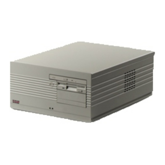
Page 28: Beetle /Xl-Ii - The Components
OVERVIEW BEETLE /XL-II - the Components Overview The following figure shows the outside of the BEETLE /XL-II. LEDs ON/OFF But ton CD-ROM Dri ve Flop py Disk Dri ve... - Page 29 OVERVIEW The figure below shows the inside of the BEETLE /XL-II. Hard Disk Ri ser Board Po wer Supp ly Unit CD-ROM Dri ve Flop py Disk Dri ve...
-
Page 30: Floppy Disk Drive
FLOPPY DISK DRIVE Floppy Disk Drive Ge ne ral The BEETLE /XL-II is equipped with a floppy disk drive for 3.5" disks. The LED at the drive lights up whenever the system accesses the drive. The disks can be used for a variety of applications, such as: Loading programs Saving data (e.g. -
Page 31: Re Mo Ving A Disk
CD-ROM DRIVE Re mo ving a Disk Press the ejection button next to the drive slot. You can now remove the disk. Never remove the disk while the drive is being accessed, i.e. when the LED indicator for the drive is illuminated. Otherwise, you could damage the drive and the disk. -
Page 32: Ope Ra Ting The Dri Ve
CD-ROM DRIVE Ope ra ting the Dri ve To start the drive, follow the procedure below: Turn on the power supply. Press the ejection button. The drawer is ejected from the drive. -
Page 33: No Tes
POWER SYPPLY UNIT Place the disc into the drawer with the discs label facing up. Then restore the drawer softly until it is locked in the drive. No tes Never bend a disc. Never write on a disc with the a hard object, like a ball-point pen or pencil and never fix a label directly on the disc. -
Page 34: Battery
BATTERY DC24V 110-120 V / 2 A max 200-240 V / 1 A max Cashdr. Only CRT/TFT LPT1 KYBD COM4 COM3 COM2 COM1 ON/OFF switch Battery The battery bridges any power failures and allows a controlled shutdown of the POS program by the appropriate software (see table below). Battery charging time is approx. -
Page 35: Chan Ging The Bat Te Ry
BATTERY Chan ging the Bat te ry All batteries have a limited service life. In order to prevent any loss of data, we recommend that you change the battery at least every five years. Make sure that the device is switched off and the power plug is dis- connected. - Page 36 ) by pressing on the anchorage (s. arrow Remove the battery. Use only batteries approved by Wincor Nixdorf. Always dispose of batteries in an environmentally safe manner. Insert the battery. Connect the plug to the jack and reinstall the battery plate with the new battery at the bottom of the BEETLE /XL-II.
-
Page 37: Configuration Variants
SUBMODULES FOR THE CPU Configuration Variants Submodules for the CPU Various controllers can be plugged in on the CPU. The following is a brief description of the available options: LAN Con trol ler 10/100 MBit This controller can be used to incorporate the BEETLE /XL-II in an Ethernet network (10/100). - Page 38 SUBMODULES FOR THE CPU Lift the top cover at the back side (1) and then shift it out of the front guide (2). Shift the side part upward. Remove the metal cover you require on the rear side. Plug in the submodule.
-
Page 39: Change Of The Cd-Rom Drive
CHANGE OF THE CD-ROM DRIVE Change of the CD-ROM Drive First ensure that the device is switched off and that the power connector is disconnected. To chan ge the CD-ROM dri ve open your BEET LE /XL-II as des cri bed abo ve. Pull out all ca ble con nec tors (see ar rows). -
Page 40: Change Of The Hard Disk Drive
CHANGE OF THE HARD DISK DRIVE Change the CD-ROM drive and fasten the new drive with the screws. Insert the CD-ROM drive holder. Make sure that the re cess in the me tal rail of the BEET LE cor re sponds with the latch of the CD-ROM dri ve hol der (see ar row). -
Page 41: Installing An Expansion Card
INSTALLING AN EXPANSION CARD Installing an Expansion Card Ex pan sion cards with elec tro sta ti c sen si ti ve de vi ces (ESD) can be mar ked with this sti cker. When you handle boards fitted with ESDs (electronic components), you must observe the following aspects under all circumstances: You must always discharge yourself (e. - Page 42 INSTALLING AN EXPANSION CARD Shift the side part up ward. There is an easy access to the AT slot now. Remove the lower metal cover at the housing by pushing the clamp (see picture). tap pet of the clamp Always use the lower slot. This slot is reserved for a PCI- or ISA-Card. First check whether the jumpers (if present) of the card are set correctly to avoid internal system conflicts.
-
Page 43: Retail Software
This means, for example, that solutions that fulfil the regional requirements of Central Europe may turn out to be inadequate for Asia or Latin America. Wincor Nixdorf provides customers world-wide with standard products appropriate to the commercial and technical complexity of their organizations. -
Page 44: Platforms And Products
Linux. Regardless of the industry involved, Linux offers itself as an interesting supplement to the world of Microsoft. In view of this trend, Wincor Nixdorf has defined a software strategy that accommodates both Linux and the popular Microsoft platform:... -
Page 45: Li Nux
Linux platform throughout. Tech no lo gy Eva lua ti on The further development of Wincor Nixdorf retail solutions takes place in dialog with its customers. Before being included in existing products, new trends and technologies are carefully examined with regard to their readiness for the market. -
Page 46: Starting Up The System
START AND RUNUP BEHAVIOUR Starting up the System Start and Runup Behaviour After installing the BEETLE /XL-II, switch on the ON/OFF switch at the rear side of your POS system and then the On button at the front panel. The system first performs an automatic self-test to test its basic functions. For example, you may see the following message (irrespective of processor type) on the four-line cashier display or on the monitor: WN ID xx/xx Date... - Page 47 START AND RUNUP BEHAVIOUR Corresponding to the Setup configuration the modular BEETLE /XL-II POS system can be booted from the following drives: Floppy disk in drive A: Hard disk in drive C: CD-ROM in EL TORITO format Network adapter with BOOTPROM Please mind that the storage medium must be system-boot-capable.
-
Page 48: Appendix
TECHNICAL DATA FOR THE BEETLE /XL-II Appendix Technical Data for the BEETLE /XL-II Width 288 mm 11.34“ Depth (without cable cover) 395 mm 15.55“ Depth (with cable cover) 470 mm 18,5“ Height 149.5 mm 5.89“ Ca ble co ver 75 mm 2.95“... -
Page 49: Rear Panels Of The Beetle /Xl-Ii
REAR PANELS OF THE BEETLE /XL-II Rear Panels of the BEETLE /XL-II DC24V 110-120 V / 2 A max 200-240 V / 1 A max Cashdr. Only CRT/TFT LPT1 COM4* COM3* COM2* COM1 KYBD LAN/ASYN Rear Pa nel of the BEET LE /XL-II (150W po wer supp ly unit) DC24V 110-120 V / 2 A max 200-240 V / 1 A max... -
Page 50: Glossary
GLOSSARY Glossary A bit is a binary digit (0 or 1). It is the smallest unit used in data processing. Bits per Pixel, depth of colour. Controller Serves to control data input and output in a data processing system or between a computer and the connected peripherals. - Page 51 GLOSSARY Peripherals Devices serving as an input/output device or storage for a computer. This includes, for example, document readers, keyboards, printers and disk storage. Server This is a computer connected to a local network and whose services are available to all of the network subscribers, e.g. a print server for printing the data from all of the network subscribers on the printer connected to the server.
-
Page 52: Abbreviations
ABBREVIATIONS Abbreviations Ad van ced Tech no lo gy AT-Attachment BIOS Ba sic In put Out put Sys tem Bits per Inch Com mu ni ca ti on Port Cen tral Pro ces sing Unit Cat ho de Ray Tube ca na da Un derwri ters La bo ra to ries DIMM Dual In li ne Me mo ry Mo du le...
Need help?
Do you have a question about the Beetle/XL-I and is the answer not in the manual?
Questions and answers