
Related Manuals for SHOWTEC Calypso 43104


Summary of Contents for SHOWTEC Calypso 43104
- Page 1 Calypso ORDERCODE 43104 Highlite International B.V. Vestastraat 2 6468 EX Kerkrade The Netherlands Phone: +31 45-5667700...
- Page 2 For more information: iwant@showtec.info You can get some of the best quality, best priced products on the market from Showtec. So next time, turn to Showtec for more great lighting equipment. Always get the best -- with Showtec ! Thank you!
-
Page 3: Table Of Contents
Showtec Showtec Calypso Product Guide ™ Warning ................................... 3 Safety Instructions ..............................3 Operating Determinations ............................5 Rigging ..................................5 Return Procedure ..............................6 Claims ..................................6 Description of the device ............................. 7 Overview ..................................8 Installation ..................................8 Set Up and Operation ..............................8 Control Modes ................................ -
Page 4: Warning
Warning FOR YOUR OWN SAFETY, PLEASE READ THIS USER MANUAL CAREFULLY BEFORE YOUR INITIAL START-UP! Unpacking Instructions Immediately upon receiving this product, carefully unpack the carton and check the contents to ensure that all parts are present, and have been received in good condition. Notify the dealer immediately and retain packing material for inspection if any parts appear damaged from shipping or the carton itself shows signs of mishandling. - Page 5 If your Showtec device fails to work properly, discontinue use immediately. Pack the unit securely (preferably in the original packing material), and return it to your Showtec dealer for service.
-
Page 6: Operating Determinations
Operating Determinations • This device is not designed for permanent operation. Consistent operation breaks will ensure that the device will serve you for a long time without defects. • The minimum distance between light-output and the illuminated surface must be more than 0,5 meter. •... -
Page 7: Return Procedure
Connection with the mains Connect the device to the mains with the power-plug. Always pay attention, that the right color cable is connected to the right place. International EU Cable UK Cable US Cable BROWN YELLOW/COPPER FASE BLUE BLACK SILVER YELLOW/GREEN GREEN GREEN... -
Page 8: Description Of The Device
Description of the device Features The Calypso is a light-effect with high output and great effects. • LED Source: 28x 5 mm RED LED; 28x 5 mm Green LED; 28x 5 mm Blue LED; 28x 5 mm White LED • Input-voltage: 100-240V Autoswitch •... -
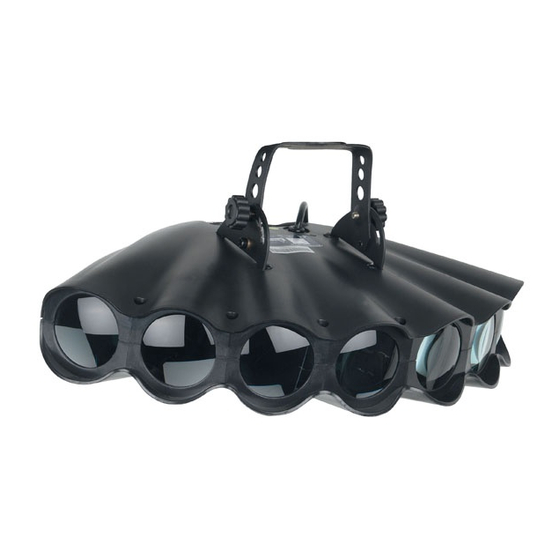
Page 9: Overview
Overview Fig. 2 1) Mountingbracket with adjustment screws for Truss mounting 2) Fixed power cable with Schuko plug 3) Fuse (T1A) 4) DMX signal connector (IN) 3-pin 5) Microphone 6) DMX address DIP switch 1-9 Allows you to set up the fixture’s DMX address. The unit is in stand-alone mode when all dipswitches are off. -
Page 10: Control Modes
Control Modes There are 3 control modes: • Single Calypso stand-alone (triggered by built-in microphone). • Multiple Calypso fixtures (Master/Slave mode). • DMX control. Single Calypso (music control) 1. Fasten the effect light onto firm trussing. Leave at least 0,5 meter on all sides for air circulation. 2. -
Page 11: Multiple Calypso Fixtures (Master/Slave Mode)
Multiple Calypso fixtures (Master/Slave Mode) 1. Fasten the effect light onto firm trussing. Leave at least 0,5 meter on all sides for air circulation. 2. Make sure the powercables off all calypso fixtures are unplugged. 3. Use a 3-p XLR cable to connect the Calypso. The pins: Earth Signal -... - Page 12 A Synchronous pattern 1) Master unit setup: Set F2 in OFF position. Check that F1 is in OFF position. F1: OFF = master. F2: OFF = synchronous pattern. 2) Slave unit(s) setup: Check that F1 is in ON position. F1: ON =slave F2: Has no function for slave units.
- Page 13 3) If you connect 8 units, make sure, the address off the fourth slave (the fifth unit) is set to1, the next at Address 2 etc. Set the address DIP switch of the first slave at 2. Address = 2 Set the address DIP switch of the second slave at 3.
-
Page 14: Multiple Calypso Fixtures (Dmx Control)
Multiple Calypso fixtures (DMX control) 1. Fasten the Calypso fixture(s) onto firm trussing. Leave at least 0,5 meter on all sides for air circulation. 2. Make sure that the powercables of all Calypso fixtures are unplugged. 3. Use a 3-p XLR cable to connect the Calypso fixture(s). -
Page 15: Dmx Channel Summary
Multiple Calypso fixtures Pro Set Up Fig. 4 Note : Link all DMX cables before connecting electric power Do not supply power before the whole system is set up and connected properly. Design your show according to your DMX controller functions. Note: It’s necessary to insert a XLR termination plug (with 120 Ohm) in the last fixture in order to ensure proper transmission on the DMX data link. - Page 16 Channel 3 – Blackout-Scenes-Flash-Full On (When Ch1 is set between 16-127 Blackout 8-241 39 Scenes 242-247 Speedy Flash 248-255 Full Light Channel 3 – Speed (when CH1 is set between 0-15 Blackout 8-241 39 Scenes 242-247 Speedy Flash 248-255 Full Light Channel 4 –...
-
Page 17: Dipswitch Setting For Dmx Mode
1 2 4 8 16 32 64 128 256 You need to know that DMX address settings are the sum of the dip switch values. A standard DMX address for a Showtec Calypso, which has 4 channels is as follows: Example:... -
Page 18: Dmx Quick Reference Chart
DMX Quick Reference Chart... -
Page 19: Fixture Linking
Fixture Linking You will need a serial data link to run light shows of one or more fixtures using a DMX-512 controller or to run synchronized shows on two or more fixtures set to a master/slave operating mode. The combined number of channels required by all the fixtures on a serial data link determines the number of fixtures the data link can support. -
Page 20: Connection Cables
4. If all of the above appears to be O.K., plug the unit in again. 5. If you are unable to determine the cause of the problem, do not open the Calypso, as this may damage the unit and the warranty will become void. 6. Return the device to your Showtec dealer. -
Page 21: No Response To Dmx
No Response to DMX Response: Suspect the DMX cable or connectors, a controller malfunction, a light effect DMX card malfunction. 1. Check the DMX setting. Make sure that DMX addresses are correct. 2. Check the DMX cable: Unplug the unit; change the DMX cable; then reconnect to electrical power. Try your DMX control again. -
Page 22: Product Specification
Product Specification Model: Showtec Calypso • LED Source: 28x 5 mm RED LED; 28x 5 mm Green LED; 28x 5 mm Blue LED; 28x 5 mm White LED • Input-voltage: 100-240V Autoswitch • Peak Power: 82W • Continuous Power: 135W •...
Need help?
Do you have a question about the Calypso 43104 and is the answer not in the manual?
Questions and answers