Table of Contents
Advertisement
Advertisement
Table of Contents

Related Manuals for Lenovo G8124-E


Summary of Contents for Lenovo G8124-E
-
Page 1: Installation Guide
Lenovo RackSwitch G8124-E Installation Guide... - Page 2 LIMITED AND RESTRICTED RIGHTS NOTICE: If data or software is delivered pursuant a General Services Administration “GSA” contract, use, reproduction, or disclosure is subject to restrictions set forth in Contract No. GS-35F-05925. Lenovo and the Lenovo logo are trademarks of Lenovo in the United States, other countries, or both.
-
Page 3: Table Of Contents
Chapter 3. Installing G8124-E Hardware and Options ..27 Before Installing the G8124-E....28 Recording Important Product Information . - Page 4 Removing the Air-Duct Option ....56 Replacing the G8124-E ..... . 57 Preparing and Returning the G8124-E .
- Page 5 Power Specifications ..... . . 76 Switching Performance ..... . 77 © Copyright Lenovo 2015 Contents...
- Page 6 G8124-E Installation Guide...
-
Page 7: Safety Information
Prima di installare questo prodotto, leggere le Informazioni sulla Sicurezza. Πред да инсталира овој продукт, прочитајте информацијата за безбедност. Les sikkerhetsinformasjonen (Safety Information) før du installerer dette produktet. Przed zainstalowaniem tego produktu, należy zapoznać się z książką “Informacje dotyczace bezpieczeństwa” (Safety Information). © Copyright Lenovo 2015 Safety Information... - Page 8 Antes de instalar este producto, lea la información de seguridad. Läs säkerhetsinformationen innan du installerar den här produkten. Bu ürünü kurmadan önce güvenlik bilgilerini okuyun. Youq mwngz yungh canjbinj neix gaxgonq, itdingh aeu doeg aen canjbinj soengq cungj vahgangj ancien suisik. G8124-E Installation Guide...
-
Page 9: Safety Statements
Laser radiation when open. Do not stare into the beam, do not view directly with optical instruments, and avoid direct exposure to the beam. Class 1 Laser Product Laser Klasse 1 Laser Klass 1 Luokan 1 Laserlaite Appareil À Laser de Classe 1 © Copyright Lenovo 2015 Safety Information... - Page 10 Overloading a branch circuit is potentially a fire hazard and a shock hazard under certain conditions. To avoid these hazards, ensure that your system electrical requirements do not exceed branch circuit protection requirements. Refer to the information that is provided with your device for electrical specifications. G8124-E Installation Guide...
- Page 11 Statement 25 CAUTION: This product contains a Class 1M laser. Do not view directly with optical instruments. Statement 26 CAUTION: Do not place any object on top of rack-mounted devices. © Copyright Lenovo 2015 Safety Information...
- Page 12 4. Attach signal cables to other 2. Remove the signal cables from the devices. connectors. 5. Connect power cords to their 3. Remove all cables from the sources. devices. 6. Turn ON all the power sources. G8124-E Installation Guide...
-
Page 13: Other Important Safety Notices
Multiple devices extended into the service position can cause your rack cabinet to tip. • If you are not using the Lenovo 9308 rack cabinet, securely anchor the rack cabinet to ensure its stability. Other Important Safety Notices Important This product is also designed for IT power distribution systems with phase-to-phase voltage of 230V. - Page 14 G8124-E Installation Guide...
-
Page 15: Chapter 1. The Rackswitch G8124-E
G8124-E (referred to as G8124-E throughout this document). The G8124-E is a 1U rack-mountable aggregation switch with unmatched line-rate Layer 2 and Layer 3 performance. The G8124-E uses a wire-speed, non-blocking switching fabric that provides simultaneous wire-speed transport of multiple packets at low latency on all ports. -
Page 16: The Documentation Cd
If you are using a Linux operating system, insert the CD into the CD or DVD drive and run the following command from the mnt/cd directory: sh.linux.sh When the CD is mounted, open the directories and documents that support your product. G8124-E Installation Guide... -
Page 17: Related Documentation
Related Documentation Additional or updated product documents may be available from the Lenovo website. Such documents may cover features not described in the original documentation that comes with the switch, or may include technical updates or corrections. You can obtain up-to-date information on the Lenovo support website: http://support.lenovo.com/... - Page 18 G8124-E Installation Guide...
-
Page 19: Chapter 2. Switch Components
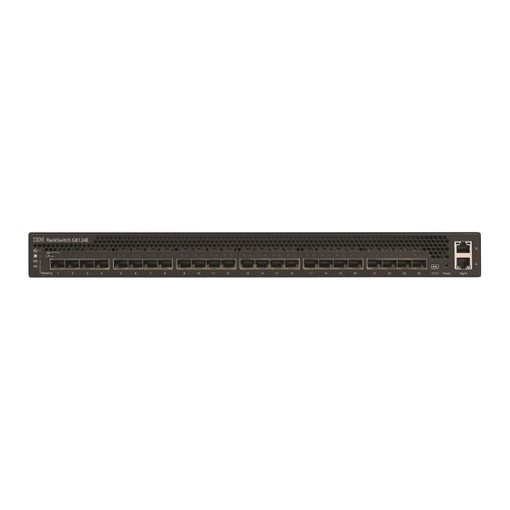
This chapter describes the G8124-E hardware components. Switch Unit The G8124-E is a 1U rack-mountable GbE switch. You can mount the switch in either the horizontal or vertical orientation. The following illustrations show the features on the front and rear of the switch. -
Page 20: Management Panel
Table 2. Console cable RJ-45 port connector pin assignments Pin Number Function RTS (Request To Send) DTR (Data Terminal Ready) TxD (Transmit Data) GND (Ground) GND (Ground) RxD (Receive Data) DSR (Data Set Ready) CTS (Clear To Send) G8124-E Installation Guide... -
Page 21: Rj-45 Management Ports
Normal reset—Press and release Reset. The switch resets and reloads the configuration files. • Factory reset—Press and hold Reset for more than five seconds. The switch resets and reverts all configuration settings to the factory defaults. © Copyright Lenovo 2015 Chapter 2: Switch Components... -
Page 22: System Status Leds
LED may be steady green, depending on the last known good state, or both LEDs may be steady green to indicate a general stacking error. Switching Ports The G8124-E contains the following switching ports: • Twenty=-four 10 GbE SFP+ ports SFP+ ports can be populated with optical or copper transceiver modules or Direct-Attach Cables (DACs). - Page 23 Status LEDs for the SFP+ ports are described in the following table. Table 5. SFP+ port status LED behavior State Functional Meaning Steady green Link up (Link/Activity) No link Flashing green Activity Steady green 10 Gbps SP (Speed) 1 Gbps or no link © Copyright Lenovo 2015 Chapter 2: Switch Components...
-
Page 24: Rear Panel
If there is a failure of one or more fans, the front panel Fan LED flashes. Power Supply For redundancy, the G8124-E includes two internal AC power supplies. Each of the two IEC 320 power connectors can be attached to a universal grounded AC power source. - Page 25 There is no power switch on the G8124-E power modules; the switch powers up when power is supplied through the power cord to one or both power supplies.
- Page 26 On the front of the switch, the Power LED on the management panel indicates the general status of the power supplies. The LED flashes when only one power cord is connected, and is steady when both power cords are connected (see “System Status LEDs” on page 22). G8124-E Installation Guide...
-
Page 27: Chapter 3. Installing G8124-E Hardware And Options
– “Installing the G8124-E in a Standard Equipment Rack” on page 33 – “Installing the G8124-E in a Lenovo System x or Power Rack” on page 35 – “Installing the G8124-E in a Lenovo iDataPlex Rack” on page 39 •... -
Page 28: Before Installing The G8124-E
Some of the product information labels may be hidden from view once the G8124-E is installed. To prevent the need to remove the switch in order to read required... -
Page 29: Required Tools
Required Tools You need the following tools or equipment to install the G8124-E: • Standard flat-blade screwdriver • #2 Phillips screwdriver • Electrostatic discharge wrist strap Package Contents The basic G8124-E package contains the following items: • One RackSwitch G8124-E unit with front-to-rear or rear-to-front airflow •... -
Page 30: Preventing Electric Shock
This product does not contain any user-serviceable parts. Do not remove the cover of this device. The G8124-E AC power module is designed to work with single-phase power systems that have a grounded neutral conductor. For your safety, a power cord with a ground attachment plug is available to order for use with this product. - Page 31 2. Remove the signal cables from the devices. connectors. 5. Connect power cords to their 3. Remove all cables from the sources. devices. 6. Turn ON all the power sources. © Copyright Lenovo 2015 Chapter 3: Installing G8124-E Hardware and Options...
-
Page 32: Handling Static-Sensitive Devices
Make sure that the radius of any bend does not exceed the vendor recommended minimum bend radius. • Do not stress cables and connectors by applying additional twists, tension beyond load ratings, stapling, or applying nylon tie-wraps with a tie-wrap puller. G8124-E Installation Guide... -
Page 33: Installing The G8124-E In A Rack
Installing the G8124-E in a Standard Equipment Rack This section describes how to install the G8124-E in a standard 19-inch equipment rack using the mounting kit included with the switch. For information about mounting the switch in other supported racks, see the appropriate section in this chapter. - Page 34 To install the G8124-E in a standard equipment rack, complete the following steps: 1. Locate, record, and retain the product switch information in order to configure and register your product. See “Recording Important Product Information” on page Note: If this switch is a replacement switch, copy the product information from the original switch onto the RID label that is shipped with replacement switch and affix the new label to the bottom of the new switch.
-
Page 35: Installing The G8124-E In A Lenovo System X Or Power Rack
57). Installing the G8124-E in a Lenovo System x or Power Rack ® This section describes how to install the G8124-E in a Lenovo System x or Power 4-post rack, using the Lenovo Adjustable 19” 4-Post Rail Kit. This kit must be purchased separately. It includes the following parts: Table 8. - Page 36 To install the G8124-E in a System x or Power rack, complete the following steps: 1. Locate, record, and retain the product switch information in order to configure and register your product. See “Recording Important Product Information” on page Note: If this switch is a replacement switch, copy the product information from the original switch onto the RID label that is shipped with replacement switch and affix the new label to the bottom of the new switch.
- Page 37 5.7 Nm ± 0.1 Nm (50 inch-pounds). 6. Slide the rear mounting brackets (Item 7 and Item 8) into the slots available on the front mounting brackets. © Copyright Lenovo 2015 Chapter 3: Installing G8124-E Hardware and Options...
- Page 38 10. Connect all external cables in accordance with the “Cabling Guidelines” on page 11. Initialize the switch. See Chapter 5, “Initializing the G8124-E,” on page 12. If the switch is a replacement unit, set Vital Product Data (see “Configuring Vital Product Data” on page 57). G8124-E Installation Guide...
-
Page 39: Installing The G8124-E In A Lenovo Idataplex Rack
Installing the G8124-E in a Lenovo iDataPlex Rack This section describes how to install the G8124-E in a Lenovo iDataPlex rack. The iDataPlex mounting kit allows the switch to be mounted either horizontally or vertically. The kit must be purchased separately. It includes the following parts: Table 9. - Page 40 M4 screws (Item 2). Torque the screws to approximately 2 newton-meters (Nm) +/- 0.1 Nm (17.7 inch-pounds). 4. From the front, slide the switch into the rack at the desired height. G8124-E Installation Guide...
- Page 41 9. Initialize the switch. See Chapter 5, “Initializing the G8124-E,” on page 10. If the switch is a replacement unit, set Vital Product Data (see “Configuring Vital Product Data” on page 57). © Copyright Lenovo 2015 Chapter 3: Installing G8124-E Hardware and Options...
-
Page 42: Installing The Air-Duct Option
Installing the Air-Duct Option The G8124-E supports an optional 1U air duct to maximize air flow conditions in a 19” rack. For information on removing an installed 1U air-duct option, see “Removing the Air-Duct Option” on page The following table lists the parts included with the air-duct option kit. - Page 43 2. Place the half shears on the rear side of the foam carriers and use the M3.5 mounting rail screws to secure the foam carrier assemblies snugly against the rear of the G8124-E unit. Torque the screws to approximately 1.1 Nm ± 0.1 Nm (10 inch-pounds).
- Page 44 3. Plug the power cords into their respective G8124-E power connectors and using tie wraps, secure the power cords to the mounting rails. Power connection Tie wraps Tie wraps Power connection 4. Secure the air-duct mounting bracket to the rails with M6 screws. Torque the screws to approximately 5.7 Nm ±...
- Page 45 Make sure that the foam strip is oriented on top. Foam Card guides thumbscrews Side flanges 7. Secure the air-duct unit to the air-duct brackets with the two M4 thumbscrews. © Copyright Lenovo 2015 Chapter 3: Installing G8124-E Hardware and Options...
-
Page 46: Installing Port Transceivers
“Installing an SFP+ Optical Transceiver” on page 47 Installing an SFP Copper Transceiver Approved 1 GbE SFP copper transceivers are supported in G8124-E SFP+ port slots. The SFP copper transceiver provides an RJ-45 connector that accepts a standard 10/100/1000BASE-T (Category 5) cable. -
Page 47: Installing An Sfp+ Optical Transceiver
After you remove the transceiver, replace the safety cap. Installing an SFP+ Optical Transceiver Approved 10 GbE SFP+ optical transceivers are supported in G8124-E SFP+ port slots. The SFP+ optical transceiver provides two fiber-optic cable connectors for connecting to external ports. - Page 48 4. Connect the fiber-optic cable following the “Cabling Guidelines” on page To remove an SFP+ optical transceiver, disconnect the fiber-optic cable, and pull down the locking lever to release the transceiver. After you remove the transceiver, replace the safety cap. G8124-E Installation Guide...
-
Page 49: Chapter 4. Removing And Replacing G8124-E Components
Removing the switch from one of the supported rack types— – “Removing the G8124-E from a Standard Equipment Rack” on page 51 – “Removing the G8124-E from a Lenovo System x or Power Rack” on page 52 – “Removing the G8124-E from a Lenovo iDataPlex Rack” on page 54 •... - Page 50 2. Pull down the locking lever to release the transceiver. 3. Gently slide the transceiver out of the switch. 4. After you remove the transceiver, replace the safety cap. To replace the transceiver module, see the appropriate section under “Installing Port Transceivers” on page G8124-E Installation Guide...
-
Page 51: Removing The G8124-E From A Standard Equipment Rack
Removing the G8124-E from a Standard Equipment Rack This section describes how to remove the G8124-E from a standard 19-inch equipment rack. For information about removing the switch from other supported racks, see the appropriate section in this chapter. To remove the G8124-E from a standard rack, complete the following steps: 1. -
Page 52: Removing The G8124-E From A Lenovo System X Or Power Rack
Removing the G8124-E from a Lenovo System x or Power Rack This section describes how to remove the G8124-E from a Lenovo System x or Power 4-post rack. To remove the G8124-E from a System x or Power rack, complete the following steps: 1. - Page 53 6. Loosen and remove the M6 screws, washers, and clip nuts (or cage nuts) connecting the front mounting brackets to the front rack posts. 7. Slide the G8124-E unit out of the rack. © Copyright Lenovo 2015 Chapter 4: Removing and Replacing G8124-E Components...
-
Page 54: Removing The G8124-E From A Lenovo Idataplex Rack
“Replacing the G8124-E” on page Removing the G8124-E from a Lenovo iDataPlex Rack This section describes how to remove the G8124-E from a Lenovo iDataPlex rack. To remove the G8124-E from an iDataPlex rack, complete the following steps: 1. Disconnect all external cables. - Page 55 5. Slide the switch out of the rack. 6. Loosen and remove the M4 screws that attach front and rear mounting brackets to each side of the switch. 7. If replacing the unit with another G8124-E, see “Replacing the G8124-E” on page ©...
-
Page 56: Removing The Air-Duct Option
Removing the Air-Duct Option The G8124-E supports an optional 1U air duct to maximize air flow conditions in a Lenovo Power Systems Group rack. To remove an installed 1U air-duct option from a 19” rack, complete the following steps. 1. Loosen the M4 thumbscrews securing the air-duct unit to the mounting brackets. -
Page 57: Replacing The G8124-E
Assistance” on page 65 to help you gather all the required information that is necessary to return a component. After you remove the G8124-E unit, securely pack it for shipping. Install the replacement G8124-E hardware as directed in Chapter 3, “Installing G8124-E Hardware and Options”... - Page 58 1000001 is the serial number of your old unit. Note: The serial number shown here is merely an example—use the actual serial number recorded from your old G8124-E unit. 5. Reset the switch using the following command: RS G8124-E (config)# reload 6.
-
Page 59: Chapter 5. Initializing The G8124-E
Chapter 5. Initializing the G8124-E When you supply power to the G8124-E, the switch initializes automatically for basic functions. Statement 5 CAUTION: The power control button on the device and the power switch on the power supply do not turn off the electrical current supplied to the device. The device also might have more than one power cord. -
Page 60: Using The Management Port
Memory Test ........ Production Mode PPCBoot 0.0.0.10 (new flash) Memory Test (0x00) ......PASSED Lenovo RS G8124-E Jan 6 00:11:36 2015: Password: At the prompt, type the switch password and press Enter. The default is admin. Note: If the switch has already started prior to your connection, you may need to press Enter to display the password prompt. -
Page 61: Configuring An Ip Interface For Remote Access
RS G8124-E (config-ip-if)# enable RS G8124-E (config-ip-if)# exit 4. Configure the default gateway. Enable the gateway. RS G8124-E (config)# ip gateway 1 address 10.10.10.1 (example gateway address) RS G8124-E (config)# ip gateway 1 enable After you configure the IP address for your switch and you have an existing network connection, you can use the Telnet program from an external management station to access and control the switch. -
Page 62: Updating Firmware
Updating Firmware If firmware updates are available, you can download them from the Lenovo website. The switch might have features that are not described in the documentation that comes with the switch, and the documentation might be updated occasionally to include information about those features, or technical updates might be available to provide additional information that is not included in the switch documentation. -
Page 63: Chapter 6. Troubleshooting
If you have problems accessing the switch or working with the firmware, see the Command Reference for the switch. For information about calling Lenovo for service, see Appendix A, “Getting Help and Technical Assistance”... - Page 64 G8124-E Installation Guide...
-
Page 65: Appendix A. Getting Help And Technical Assistance
If you need help, service, or technical assistance or just want more information about Lenovo products, you will find a wide variety of sources available from Lenovo to assist you. This appendix will help you obtain additional information about Lenovo and Lenovo products, and determine what to do if you experience a problem with your Lenovo system or optional device. - Page 66 G8124-E Installation Guide...
-
Page 67: Appendix B. Notices
Web sites. The materials at those Web sites are not part of the materials for this Lenovo product, and use of those Web sites is at your own risk. -
Page 68: Trademarks
(TBW). A device that has exceeded this limit might fail to respond to system-generated commands or might be incapable of being written to. Lenovo is not responsible for replacement of a device that has exceeded its maximum guaranteed number of program/erase cycles, as documented in the Official Published Specifications for the device. -
Page 69: Recycling Information
Lenovo makes no representations or warranties with respect to non-Lenovo products. Support (if any) for the non-Lenovo products is provided by the third party, not Lenovo. Some software might differ from its retail version (if available) and might not include user manuals or all program functionality. -
Page 70: Particulate Contamination
If Lenovo determines that the levels of particulates or gases in your environment have caused damage to the device, Lenovo may condition provision of repair or replacement of devices or parts on implementation of appropriate remedial measures to mitigate such environmental contamination. -
Page 71: Telecommunication Regulatory Statement
Further certification may be required by law prior to making any such connection. Contact a Lenovo representative or reseller for any questions. Electronic Emission Notices When you attach a monitor to the equipment, you must use the designated monitor cable and any interference suppression devices that are supplied with the monitor. -
Page 72: Germany Class A Statement
EU-Mitgliedsstaaten und hält die Grenzwerte der EN 55022 Klasse A ein. Um dieses sicherzustellen, sind die Geräte wie in den Handbüchern beschrieben zu installieren und zu betreiben. Des Weiteren dürfen auch nur von der Lenovo empfohlene Kabel angeschlossen werden. Lenovo übernimmt keine Verantwortung für die Einhaltung der Schutzanforderungen, wenn das Produkt ohne Zustimmung... -
Page 73: Vcci Class A Statement
Korea Communications Commission (KCC) Statement This is electromagnetic wave compatibility equipment for business (Type A). Sellers and users need to pay attention to it. This is for any areas other than home. © Copyright Lenovo 2015 Appendix B: Notices... -
Page 74: Russia Electromagnetic Interference (Emi) Class A Statement
Russia Electromagnetic Interference (EMI) Class A Statement People’s Republic of China Class A Electronic Emission Statement Taiwan Class A Compliance Statement G8124-E Installation Guide... -
Page 75: Appendix C. Technical Specifications
Appendix C. Technical Specifications The G8124-E technical specifications are described in the following sections. Physical Characteristics The physical characteristics of the G8124-E are listed in the following table. Table 11. Physical characteristics Specification Physical characteristics Dimensions (H x W x D) 4.4 x 43.9 x 38.1 cm... -
Page 76: Power Specifications
Power Specifications The power specifications for the G8124-E are listed in the following table. Table 13. G8124-E AC power specifications Specification Measurement Number of power supplies 2 (1+1 load sharing/redundant) AC-input frequency (universal) 50–60 Hz AC-input voltage (universal) 100–240 VAC... -
Page 77: Switching Performance
Switching Performance The feature performance characteristics of the G8124-E are listed in the following table. Table 14. G8124-E feature performance characteristics Feature Characteristics Switching architecture Non-blocking Throughput 240 Gbps full-duplex Ethernet line rate 100% Deterministic port-to-port latency less than 700 ns with 64-byte packets IEEE 802.1Q VLANs... - Page 78 G8124-E Installation Guide...
Need help?
Do you have a question about the G8124-E and is the answer not in the manual?
Questions and answers