Lenovo RackSwitch G8264CS Installation Manual
Hide thumbs
Also See for RackSwitch G8264CS:
- Cli command reference (703 pages) ,
- Application manual (634 pages) ,
- Product manual (27 pages)
Table of Contents
Advertisement
Quick Links
Advertisement
Table of Contents

Subscribe to Our Youtube Channel
Related Manuals for Lenovo RackSwitch G8264CS


Summary of Contents for Lenovo RackSwitch G8264CS
- Page 1 Lenovo RackSwitch G8264CS Installation Guide...
- Page 2 LIMITED AND RESTRICTED RIGHTS NOTICE: If data or software is delivered pursuant a General Services Administration “GSA” contract, use, reproduction, or disclosure is subject to restrictions set forth in Contract No. GS-35F-05925. Lenovo and the Lenovo logo are trademarks of Lenovo in the United States, other countries, or both.
-
Page 3: Safety Information
Prima di installare questo prodotto, leggere le Informazioni sulla Sicurezza. Πред да инсталира овој продукт, прочитајте информацијата за безбедност. Les sikkerhetsinformasjonen (Safety Information) før du installerer dette produktet. Przed zainstalowaniem tego produktu, należy zapoznać się z książką “Informacje dotyczace bezpieczeństwa” (Safety Information). © Copyright Lenovo 2015 Safety Information... - Page 4 Antes de instalar este produto, leia as Informações sobre Segurança. Перед установкой продукта прочтитe инcтрyкции по тexникe безопасности. Pred inštaláciou tohto zariadenia si prečítajte Bezpečnostné predpisy. Pred namestitvijo tega proizvoda preberite Varnostne informacije. Antes de instalar este producto, lea la información de seguridad. Läs säkerhetsinformationen innan du installerar den här produkten.
-
Page 5: Safety Statements
Laser radiation when open. Do not stare into the beam, do not view directly with optical instruments, and avoid direct exposure to the beam. Class 1 Laser Product Laser Klasse 1 Laser Klass 1 Luokan 1 Laserlaite Appareil À Laser de Classe 1 © Copyright Lenovo 2015 Safety Information... - Page 6 Statement 5 CAUTION: The power control button on the device and the power switch on the power supply do not turn off the electrical current supplied to the device. The device also might have more than one power cord. To remove all electrical current from the device, ensure that all power cords are disconnected from the power source.
- Page 7 Statement 25 CAUTION: This product contains a Class 1M laser. Do not view directly with optical instruments. Statement 26 CAUTION: Do not place any object on top of rack-mounted devices. © Copyright Lenovo 2015 Safety Information...
- Page 8 Statement 31 DANGER Electrical current from power, telephone, and communication cables is hazardous. To avoid a shock hazard: • Do not connect or disconnect any cables or perform installation, maintenance, or reconfiguration of this product during an electrical storm. • Connect all power cords to a properly wired and grounded power source.
-
Page 9: Other Important Safety Notices
Multiple devices extended into the service position can cause your rack cabinet to tip. • If you are not using the Lenovo 9308 rack cabinet, securely anchor the rack cabinet to ensure its stability. Other Important Safety Notices Important This product is also designed for IT power distribution systems with phase-to-phase voltage of 230V. - Page 10 G8264CS Installation Guide...
-
Page 11: Table Of Contents
Other Important Safety Notices ....9 Chapter 1. The RackSwitch G8264CS ....15 Introduction . - Page 12 Removing the G8264CS from a Lenovo System x or Power Rack ..66 Removing the G8264CS from a Lenovo iDataPlex Rack ..68 Removing the Air-Duct Option ....70 Replacing the G8264CS .
- Page 13 Power Specifications ..... . . 94 Switching Performance ..... . 95 © Copyright Lenovo 2015 Contents...
- Page 14 G8264CS Installation Guide...
-
Page 15: Chapter 1. The Rackswitch G8264Cs
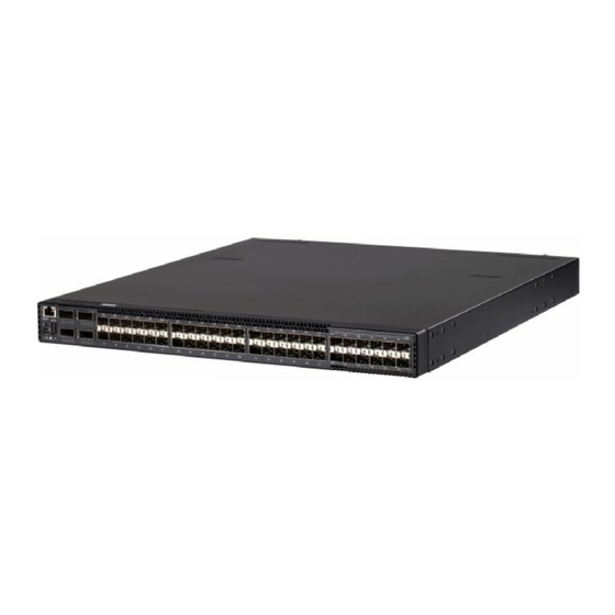
Chapter 1. The RackSwitch G8264CS Introduction ® ™ This Installation Guide provides information about the Lenovo RackSwitch G8264CS (referred to as G8264CS throughout this document). The G8264CS is a 1U rack‐mountable aggregation switch with unmatched line‐rate Layer 2 and Layer 3 performance. The G8264CS uses a wire‐speed, non‐blocking switching fabric that provides simultaneous wire‐speed transport of Ethernet packets at low latency on all ports. In addition to support for Layer 2 and Layer 3 switching and routing, the G8264CS converged switch provides Converged Enhanced Ethernet (CEE), Fibre Channel over Ethernet (FCoE), Fibre Channel(FC)/FCoE, NPV (N_Port Virtualization) Gateway, and Full Fabric FC/FCoE switching. The G8264CS contains the following switching ports: Thirty‐six 10 Gigabit Ethernet (GbE) Small Form Pluggable Plus (SFP+) ports which also support legacy 1 GbE connections Four 40 GbE Quad Small Form Pluggable Plus (QSFP+) ports, each of which can optionally be used as four 10 GbE SFP+ ports Twelve Omni Ports, of which each pair can be used either as two 10 GbE SFP+ ports or as two Fibre Channel ports independently capable of 4 or 8 Gbps QSFP+ ports can be populated with optical QSFP+ modules or Direct‐Attach Cables (DACs), including those that allow the port to be used as four 10 GbE SFP+ ports. SFP+ ports can be populated with optical or copper transceiver modules or DACs. The G8264CS is 1U in height and can be mounted horizontally or vertically, depending on your application. Mounting options are available for a variety of rack systems. For superior reliability, the G8264CS uses redundant, hot‐swap power supply ... -
Page 16: G8264Cs Documentation
G8264CS Documentation About this Installation Guide This Installation Guide provides information and instructions for installing the G8264CS, updating the firmware, and solving problems. For other information about configuration and management of the switch, refer to the documents described in “Related Documentation” on page Note: The illustrations in this document might differ slightly from your hardware. The console output described or referenced in this document might differ slightly from that displayed by your system. Output varies according to the type of Lenovo chassis and the firmware versions and options that are installed. Notices and Statements in this Document The caution and danger statements in this document are also in the multilingual Safety Information document, which is on the included Documentation CD. Each statement is numbered for reference to the corresponding statement in the Safety Information document. The following notices and statements are used in this document: Note: These notices provide important tips, guidance, or advice. Important: These notices provide information or advice that might help you avoid inconvenient or problem situations. Attention: These notices indicate potential damage to programs, devices, or data. An attention notice is placed just before the instruction or situation in which damage could occur. Caution: These statements indicate situations that can be potentially hazardous to you. A caution statement is placed just before the description of a potentially ... -
Page 17: The Documentation Cd
To access the documents on the CD: If you are using a Windows operating system, insert the CD into the CD or DVD drive and from My Computer, double click the CD or DVD drive, then open the folders and documents that support your product. If you are using a Linux operating system, insert the CD into the CD or DVD drive and run the following command from the mnt/cd directory: sh.linux.sh When the CD is mounted, open the directories and documents that support your product. Related Documentation Additional or updated product documents may be available from the Lenovo website. Such documents may cover features not described in the original documentation that comes with the switch, or may include technical updates or corrections. You can obtain up‐to‐date information on the Lenovo support website: http://support.lenovo.com/ Note: Changes are made periodically to the Lenovo website. Procedures for locating firmware and documentation might vary slightly from what is described in this document. For information about switch hardware and firmware features, specifications, and standards, including their configuration, see the Application Guide for your specific switch and its installed firmware. For information about the switch information, statistics, and individual configuration parameters, see the Command Reference guide for your specific switch and its installed firmware. For a list of compatible switch components and options (such as rack‐mounting kits, modules, cords, and cables), see the Lenovo Networking Catalog. © Copyright Lenovo 2015 Chapter 1: The RackSwitch G8264CS... - Page 18 G8264CS Installation Guide...
-
Page 19: Chapter 2. Switch Components
Panel Mode LEDs 40Gb Ethernet Ports 10Gb Ethernet Ports Omni Ports (QSFP+) (SFP+) (SFP+) Figure 2. RackSwitch G8264CS management panel detail RJ-45 Management Port Reset Button USB Port Mini-USB Serial Console Port Status LEDs Figure 3. RackSwitch G8264CS rear panel... -
Page 20: Management Panel
Management Panel Mini-USB Serial Console Port The mini-USB port on the front management panel is available for switch console management. The port operates using RS-232 serial communications. A compatible console cable kit is included with the switch. To connect a computer or terminal to the switch using the included kit, first connect the console cable to the mini-USB port on the front panel. -
Page 21: Rj-45 Management Port
Normal reset—Press and release Reset. The switch resets and reloads the configuration files. • Factory reset—Press and hold Reset for more than five seconds. The switch resets and reverts all configuration settings to the factory defaults. © Copyright Lenovo 2015 Chapter 2: Switch Components... -
Page 22: System Status Leds
USB drive, or from the USB drive to the switch. You can also start the switch using files on the USB drive. For more information about using the USB drive, see the Lenovo RackSwitch G8264CS Release Notes. -
Page 23: Switching Ports
Laser radiation when open. Do not stare into the beam, do not view directly with optical instruments, and avoid direct exposure to the beam. Class 1 Laser Product Laser Klasse 1 Laser Klass 1 Luokan 1 Laserlaite Appareil À Laser de Classe 1 © Copyright Lenovo 2015 Chapter 2: Switch Components... -
Page 24: Qsfp+ Ports
Forty-eight 10 GbE SFP+ ports are available on the front panel. These ports accept supported optical or copper SFP or SFP+ transceivers, or DACs. Transceivers must be purchased separately. Forty-eight 10 GbE SFP+ ports are available on the front panel (including the twelve Omni Ports). - Page 25 QSFP+ optical transceiver with MTP-to-4 LC (SFP+) fiber breakout cable. This option supports only Lenovo 10GBASE-SR SFP+ transceivers. The 40GBASE-SR4 specification (802.3ba-2010) indicates a higher optical power level than standard 10GBASE-SR. Lenovo SFP+ SR transceivers can handle the higher optical power levels. This cable must be purchased separately. •...
-
Page 26: Omni Ports
Omni Ports Statement 3 CAUTION: When laser products (such as CD-ROMs, DVD drives, fiber optic devices, or transmitters) are installed, note the following: • Do not remove the covers. Removing the covers of the laser product could result in exposure to hazardous laser radiation. There are no serviceable parts inside the device. -
Page 27: Rear Panel
Fan operation and internal temperatures are monitored. If the air temperature exceeds a desired threshold, the environmental monitor displays warnings. Note: If a fan fails, the maximum operating temperature drops from +40°C (104°F) to +35°C (95°F). © Copyright Lenovo 2015 Chapter 2: Switch Components... -
Page 28: Power Supply
The rear panel of the G8264CS has two bays for hot-swap power supply modules. Each power supply module has an individual IEC 320 C14 power connector. The power cord attaches to a universal grounded AC power source. Compatible power options are listed in the Lenovo Networking Catalog. Statement 5 CAUTION: The power control button on the device and the power switch on the power supply do not turn off the electrical current supplied to the device. - Page 29 When used in a redundant configuration, the dual power supplies have a load-sharing capability that enables each power supply to operate at approximately 50 percent of full load. © Copyright Lenovo 2015 Chapter 2: Switch Components...
- Page 30 Using redundant power can minimize the power disruption during a power supply failure and extend the expected lifetime of each power supply by operating normally in a conservative power mode. For proper airflow when operating the switch with only one power supply module, the empty power supply bay must be protected by a blank cover module.
- Page 31 Power supply is operational. Green DC output power is present. DC output power is OK. Green AC power is OK. No power. Output is disabled, or input power is outside operating range. © Copyright Lenovo 2015 Chapter 2: Switch Components...
- Page 32 G8264CS Installation Guide...
-
Page 33: Chapter 3. Installing G8264Cs Hardware And Options
– “Installing the G8264CS in a Standard Equipment Rack” on page 39 – “Installing the G8264CS in a Lenovo System x or Power Rack” on page 41 – “Installing the G8264CS in a Lenovo iDataPlex Rack” on page 45 •... -
Page 34: Before Installing The G8264Cs
Print this page and record product information below. Keep the information in a safe place for future reference. You will need this information when you register the switch or open a service call with Lenovo. Table 10. Important product information... -
Page 35: Required Tools
Electrostatic discharge wrist strap Package Contents The basic G8264CS package contains the following items: • One RackSwitch G8264CS unit with front-to-rear or rear-to-front airflow • One two-post mounting kit for standard 19” equipment racks: – Two mounting brackets – Screws to attach brackets to the switch unit –... -
Page 36: Preventing Electric Shock
Preventing Electric Shock This product does not contain any user-serviceable parts. Do not remove the cover of this device. The G8264CS AC power module is designed to work with single-phase power systems that have a grounded neutral conductor. For your safety, a power cord with a ground attachment plug is available to order for use with this product. - Page 37 2. Remove the signal cables from the devices. connectors. 5. Connect power cords to their 3. Remove all cables from the sources. devices. 6. Turn ON all the power sources. © Copyright Lenovo 2015 Chapter 3: Installing G8264CS Hardware and Options...
-
Page 38: Handling Static-Sensitive Devices
Handling Static-Sensitive Devices Attention: Static electricity can damage the switch and other electronic devices. To avoid damage, keep static-sensitive devices in their static-protective packages until you are ready to install them. To reduce the possibility of electrostatic discharge, observe the following precautions: •... -
Page 39: Installing The G8264Cs In A Rack
Installation instructions begin on page ® • For a Lenovo System x or Power 4-post rack, use the Lenovo Adjustable 19” 4-Post Rail Kit. This kit must be purchased separately. Installation instructions begin on page ®... - Page 40 To install the G8264CS in a standard equipment rack, complete the following steps: 1. Locate, record, and retain the product switch information in order to configure and register your product. See “Recording Important Product Information” on page Note: If this switch is a replacement switch, copy the product information from the original switch onto the RID label that is shipped with replacement switch and affix the new label to the bottom of the new switch.
-
Page 41: Installing The G8264Cs In A Lenovo System X Or Power Rack
71). Installing the G8264CS in a Lenovo System x or Power Rack ® This section describes how to install the G8264CS in a Lenovo System x or Power 4-post rack, using the Lenovo Adjustable 19” 4-Post Rail Kit. This kit must be purchased separately. It includes the following parts: Table 12. - Page 42 To install the G8264CS in a System x or Power rack, complete the following steps: 1. Locate, record, and retain the product switch information in order to configure and register your product. See “Recording Important Product Information” on page Note: If this switch is a replacement switch, copy the product information from the original switch onto the RID label that is shipped with replacement switch and affix the new label to the bottom of the new switch.
- Page 43 5.7 Nm ± 0.1 Nm (50 inch-pounds). 6. Slide the rear mounting brackets (Item 7 and Item 8) into the slots available on the front mounting brackets. © Copyright Lenovo 2015 Chapter 3: Installing G8264CS Hardware and Options...
- Page 44 7. Attach the filler plate (Item 9) and rear mounting brackets to the rear rack posts with M6 screws (Item 3), washers (Item 10), and either clip nuts (Item 4) or cage nuts (Item 5). Torque the screws to approximately 5.7 Nm ± 0.1 Nm (50 inch-pounds).
-
Page 45: Installing The G8264Cs In A Lenovo Idataplex Rack
Installing the G8264CS in a Lenovo iDataPlex Rack This section describes how to install the G8264CS in a Lenovo iDataPlex rack. The iDataPlex mounting kit allows the switch to be mounted either horizontally or vertically. The kit must be purchased separately. It includes the following parts: Table 13. - Page 46 To install the G8264CS in an iDataPlex rack, complete the following steps: 1. Locate, record, and retain the product switch information in order to configure and register your product. See “Recording Important Product Information” on page Note: If this switch is a replacement switch, copy the product information from the original switch onto the RID label that is shipped with replacement switch and affix the new label to the bottom of the new switch.
- Page 47 9. Initialize the switch. See Chapter 5, “Initializing the G8264CS,” on page 10. If the switch is a replacement unit, set Vital Product Data (see “Configuring Vital Product Data” on page 71). © Copyright Lenovo 2015 Chapter 3: Installing G8264CS Hardware and Options...
-
Page 48: Installing The Air-Duct Option
Installing the Air-Duct Option The G8264CS supports an optional 1U air duct to maximize air flow conditions in a 19” rack. For information on removing an installed 1U air-duct option, see “Removing the Air-Duct Option” on page The following table lists the parts included with the air-duct option kit. Table 14. - Page 49 G8264CS unit. Torque the screws to approximately 1.1 Nm ± 0.1 Nm (10 inch-pounds). Foam carrier snug against rear of unit Reuse mounting screws Half shear Mounting screws Note: There are additional M3.5 screws in the air-duct assembly kit. © Copyright Lenovo 2015 Chapter 3: Installing G8264CS Hardware and Options...
- Page 50 3. Plug the power cords into their respective G8264CS power connectors and using tie wraps, secure the power cords to the mounting rails. Power connection Tie wraps Tie wraps Power connection 4. Secure the air-duct mounting bracket to the rails with M6 screws. Torque the screws to approximately 5.7 Nm ±...
- Page 51 Make sure that the foam strip is oriented on top. Foam Card guides thumbscrews Side flanges 7. Secure the air-duct unit to the air-duct brackets with the two M4 thumbscrews. © Copyright Lenovo 2015 Chapter 3: Installing G8264CS Hardware and Options...
-
Page 52: Installing Port Transceivers
Installing Port Transceivers The G8264CS supports copper and optical transceivers. To install a supported transceiver, see the following sections: • “Installing an SFP Copper Transceiver” on page 52 • “Installing an SFP Optical Transceiver” on page 52 • “Installing an SFP+ Optical Transceiver” on page 54 •... - Page 53 To remove an SFP optical transceiver, disconnect the fiber-optic cable, and pull down the locking lever to release the transceiver. After you remove the transceiver, replace the safety cap. © Copyright Lenovo 2015 Chapter 3: Installing G8264CS Hardware and Options...
-
Page 54: Installing An Sfp+ Optical Transceiver
Installing an SFP+ Optical Transceiver Approved 10 GbE SFP+ optical transceivers are supported in G8264CS SFP+ port slots and in some breakout adapters that can be installed in QSFP+ port slots. The SFP+ optical transceiver provides two fiber-optic cable connectors for connecting to external ports. -
Page 55: Installing A Qsfp+ Optical Transceiver
Class 1 Laser Product Laser Klasse 1 Laser Klass 1 Luokan 1 Laserlaite Appareil À Laser de Classe 1 © Copyright Lenovo 2015 Chapter 3: Installing G8264CS Hardware and Options... -
Page 56: Installing An Omni Port Optical Transceiver
To install a QSFP+ optical transceiver in a QSFP+ port, complete the following steps. Note: To avoid damage to the cable or the QSFP+ transceiver, do not connect the cable before you install the transceiver. 1. Remove the safety cap and pull the locking lever into the down (unlocked) position. - Page 57 To remove the transceiver, disconnect the cable, and pull down the locking lever to release the transceiver. After you remove the transceiver, replace the safety cap. © Copyright Lenovo 2015 Chapter 3: Installing G8264CS Hardware and Options...
- Page 58 G8264CS Installation Guide...
-
Page 59: Chapter 4. Removing And Replacing G8264Cs Components
Removing the switch from one of the supported rack types— – “Removing the G8264CS from a Standard Equipment Rack” on page 65 – “Removing the G8264CS from a Lenovo System x or Power Rack” on page 66 – “Removing the G8264CS from a Lenovo iDataPlex Rack” on page 68 •... -
Page 60: Removing And Replacing A Power Supply Module
To remove one of the installed SFP, SFP+, or QSFP+ transceiver modules from the switch, complete the following steps. 1. Disconnect the port cable from the transceiver. 2. Pull down the locking lever to release the transceiver. 3. Gently slide the transceiver out of the switch. 4. - Page 61 Assistance” on page 79 to help you gather all the required information that is necessary to return a component. After you remove the component, securely pack the component for shipping. © Copyright Lenovo 2015 Chapter 4: Removing and Replacing G8264CS Components...
-
Page 62: Replacing The Power Supply Module
Replacing the Power Supply Module Statement 31 DANGER Electrical current from power, telephone, and communication cables is hazardous. To avoid a shock hazard: • Do not connect or disconnect any cables or perform installation, maintenance, or reconfiguration of this product during an electrical storm. •... -
Page 63: Removing And Replacing A Fan Module
To remove a hot-swap fan module, complete the following steps: 1. Loosen the retainer screw. 2. Grasp the extractor handle and gently pull the fan module from the slot. Retainer Screw © Copyright Lenovo 2015 Chapter 4: Removing and Replacing G8264CS Components... -
Page 64: Replacing The Fan Module
Attention: If the inlet air temperature is above 35°C (95°F) while the switch is in operation, replace the fan module within five minutes to avoid overheating the switch. To return the component to customer service for replacement, see Appendix A, “Getting Help and Technical Assistance”... -
Page 65: Removing The G8264Cs From A Standard Equipment Rack
5. Loosen and remove the M4 screws attaching the mounting bracket on each side of the switch. 6. If replacing the unit with another G8264CS, see “Replacing the G8264CS” on page © Copyright Lenovo 2015 Chapter 4: Removing and Replacing G8264CS Components... -
Page 66: Removing The G8264Cs From A Lenovo System X Or Power Rack
Removing the G8264CS from a Lenovo System x or Power Rack This section describes how to remove the G8264CS from a Lenovo System x or Power 4-post rack. To remove the G8264CS from a System x or Power rack, complete the following steps: 1. - Page 67 6. Loosen and remove the M6 screws, washers, and clip nuts (or cage nuts) connecting the front mounting brackets to the front rack posts. 7. Slide the G8264CS unit out of the rack. © Copyright Lenovo 2015 Chapter 4: Removing and Replacing G8264CS Components...
-
Page 68: Removing The G8264Cs From A Lenovo Idataplex Rack
“Replacing the G8264CS” on page Removing the G8264CS from a Lenovo iDataPlex Rack This section describes how to remove the G8264CS from a Lenovo iDataPlex rack. To remove the G8264CS from an iDataPlex rack, complete the following steps: 1. Disconnect all external cables. - Page 69 6. Loosen and remove the M4 screws that attach front and rear mounting brackets to each side of the switch. 7. If replacing the unit with another G8264CS, see “Replacing the G8264CS” on page © Copyright Lenovo 2015 Chapter 4: Removing and Replacing G8264CS Components...
-
Page 70: Removing The Air-Duct Option
Removing the Air-Duct Option The G8264CS supports an optional 1U air duct to maximize air flow conditions in a Lenovo Power Systems Group rack. To remove an installed 1U air-duct option from a 19” rack, complete the following steps. 1. Loosen the M4 thumbscrews securing the air-duct unit to the mounting brackets. -
Page 71: Replacing The G8264Cs
2. Use the following CLI commands to enter the Executive configuration mode: RS 8264CS> enable Enable privilege granted RS 8264CS# configure terminal Enter configuration commands, one per line. End with Ctrl/Z. RS 8264CS (config)# © Copyright Lenovo 2015 Chapter 4: Removing and Replacing G8264CS Components... - Page 72 System Information at 0:11:46 Wed Jan 6, 2015 Time zone: America/US/Pacific Daylight Savings Time Status: Disabled Lenovo RackSwitch G8264CS Switch has been up for 0 days, 0 hours, 10 minutes and 45 seconds. Last boot: 0:11:36 Wed Jan 6, 2015 (reset from console) MAC address: fc:cf:62:9d:2b:00 IP (If 1) address: 192.168.49.50...
-
Page 73: Chapter 5. Initializing The G8264Cs
You can access the switch CLI through the serial console port on the front panel of the switch. This port uses RS-232 serial communications. Use the console cable kit to connect the serial console port to a terminal or a computer running a terminal emulation program. © Copyright Lenovo 2015... -
Page 74: Using The Management Port
Memory Test ........ Production Mode PPCBoot 0.0.0.10 (new flash) Memory Test (0x00) ......PASSED Lenovo RS 8264CS Jan 6 00:11:36 2015: Password: At the prompt, type the switch password and press Enter. The default is admin. Note: If the switch has already started prior to your connection, you may need to press Enter to display the password prompt. -
Page 75: Configuring An Ip Interface For Remote Access
In addition, you can configure the switch for management using an SNMP-based network management system or a web-browser. For more information about using the CLI, see the Command Reference guide for your specific switch and firmware version. © Copyright Lenovo 2015 Chapter 5: Initializing the G8264CS... -
Page 76: Updating Firmware
Updating Firmware If firmware updates are available, you can download them from the Lenovo website. The switch might have features that are not described in the documentation that comes with the switch, and the documentation might be updated occasionally to include information about those features, or technical updates might be available to provide additional information that is not included in the switch documentation. -
Page 77: Chapter 6. Troubleshooting
If you have problems accessing the switch or working with the firmware, see the Command Reference for the switch. For information about calling Lenovo for service, see Appendix A, “Getting Help and Technical Assistance”... - Page 78 G8264CS Installation Guide...
-
Page 79: Appendix A. Getting Help And Technical Assistance
Lenovo to assist you. This appendix will help you obtain additional information about Lenovo and Lenovo products, and determine what to do if you experience a problem with your Lenovo system or optional device. Note: This section includes references to IBM web sites and information in regard to obtaining service. IBM is Lenovoʹs preferred service provider for the System x, Flex System, and NeXtScale System products. You can solve many problems without outside assistance by following the troubleshooting procedures that Lenovo provides in the online help or in the Lenovo product documentation. The Lenovo product documentation also describes the diagnostic tests that you can perform. The documentation for most systems, operating systems, and programs contains troubleshooting procedures and explanations of error messages and error codes. If you suspect a software problem, see the documentation for the operating system or program. Before you call, make sure that you have taken these steps to try to resolve the problem yourself. Check all cables to make sure that they are connected. Check the power switches to make sure that the system and any optional devices are turned on. Check for updated software, firmware and operating‐system device drivers for your Lenovo product. The Lenovo Warranty terms and conditions state that you, the owner of the Lenovo product, are responsible for maintaining and updating all software or firmware for the product (unless it is covered by an additional maintenance contract). Your service technician will request that you upgrade your software or firmware if the problem has a documented solution within a software or firmware upgrade. If you have installed new hardware or software in your environment, check the IBM ServerProven website to make sure that the hardware and software is supported by your product. Go to the IBM Support portal to check for information to help you solve the problem, and for other support options. © Copyright Lenovo 2015... - Page 80 If you believe that you require warranty service for your Lenovo product, gather the following information to provide to the service technician. This data will help the service technician quickly provide a solution to your problem and ensure that you receive the level of service for which you might have contracted. The service technicians will be able to assist you more efficiently if you prepare before you call. Hardware and Software Maintenance agreement contract numbers, if applicable Machine type number (Lenovo 4‐digit machine identifier) Model number Serial number Current system UEFI and firmware levels Other pertinent information such as error messages and logs G8264CS Installation Guide...
-
Page 81: Appendix B. Notices
Lenovo may have patents or pending patent applications covering subject matter described in this document. The furnishing of this document does not give you any license to these patents. You can send license inquiries, in writing, to: Lenovo (United States), Inc. 1009 Think Place ‐ Building One Morrisville, NC 27560 U.S.A. Attention: Lenovo Director of Licensing LENOVO PROVIDES THIS PUBLICATION “AS IS” WITHOUT WARRANTY OF ANY KIND, EITHER EXPRESS OR IMPLIED, INCLUDING, BUT NOT LIMITED TO, THE IMPLIED WARRANTIES OF NON‐INFRINGEMENT, MERCHANTABILITY OR FITNESS FOR A PARTICULAR PURPOSE. Some jurisdictions do not allow disclaimer of express or implied warranties in certain transactions, therefore, this statement may not apply to you. This information could include technical inaccuracies or typographical errors. Changes are periodically made to the information herein; these changes will be incorporated in new editions of the publication. Lenovo may make improvements and/or changes in the product(s) and/or the program(s) described in this publication at any time without notice. The products described in this document are not intended for use in implantation or other life support applications where malfunction may result in injury or death to persons. The information contained in this document does not affect or change Lenovo product specifications or warranties. Nothing in this document shall operate as an express or implied license or indemnity under the intellectual property rights of Lenovo or third parties. All information contained in this document was obtained in specific environments and is presented as an illustration. The result obtained in other operating environments may vary. Lenovo may use or distribute any of the information you supply in any way it believes appropriate without incurring any obligation to you. Any references in this publication to non‐Lenovo Web sites are provided for convenience only and do not in any manner serve as an endorsement of those Web sites. The materials at those Web sites are not part of the materials for this Lenovo product, and use of those Web sites is at your own risk. © Copyright Lenovo 2015... - Page 82 Any performance data contained herein was determined in a controlled environment. Therefore, the result obtained in other operating environments may vary significantly. Some measurements may have been made on development‐level systems and there is no guarantee that these measurements will be the same on generally available systems. Furthermore, some measurements may have been estimated through extrapolation. Actual results may vary. Users of this document should verify the applicable data for their specific environment. G8264CS Installation Guide...
-
Page 83: Trademarks
Trademarks Lenovo, the Lenovo logo, Flex System, System x, NeXtScale System, and X‐Architecture are trademarks of Lenovo in the United States, other countries, or both. Intel and Intel Xeon are trademarks of Intel Corporation in the United States, other countries, or both. Internet Explorer, Microsoft, and Windows are trademarks of the Microsoft group of companies. Linux is a registered trademark of Linus Torvalds. Other company, product, or service names may be trademarks or service marks of others. © Copyright Lenovo 2015 Appendix B: Notices... -
Page 84: Important Notes
Important Notes Processor speed indicates the internal clock speed of the microprocessor; other factors also affect application performance. CD or DVD drive speed is the variable read rate. Actual speeds vary and are often less than the possible maximum. When referring to processor storage, real and virtual storage, or channel volume, KB stands for 1 024 bytes, MB stands for 1 048 576 bytes, and GB stands for 1 073 741 824 bytes. When referring to hard disk drive capacity or communications volume, MB stands for 1 000 000 bytes, and GB stands for 1 000 000 000 bytes. Total user‐accessible capacity can vary depending on operating environments. Maximum internal hard disk drive capacities assume the replacement of any standard hard disk drives and population of all hard‐disk‐drive bays with the largest currently supported drives that are available from Lenovo. Maximum memory might require replacement of the standard memory with an optional memory module. Each solid‐state memory cell has an intrinsic, finite number of write cycles that the cell can incur. Therefore, a solid‐state device has a maximum number of write cycles that it can be subjected to, expressed as total bytes written (TBW). A device that has exceeded this limit might fail to respond to system‐generated commands or might be incapable of being written to. Lenovo is not responsible for replacement of a device that has exceeded its maximum guaranteed number of program/erase cycles, as documented in the Official Published Specifications for the device. Lenovo makes no representations or warranties with respect to non‐Lenovo products. Support (if any) for the non‐Lenovo products is provided by the third party, not Lenovo. Some software might differ from its retail version (if available) and might not include user manuals or all program functionality. G8264CS Installation Guide... -
Page 85: Recycling Information
Recycling information Lenovo encourages owners of information technology (IT) equipment to responsibly recycle their equipment when it is no longer needed. Lenovo offers a variety of programs and services to assist equipment owners in recycling their IT products. For information on recycling Lenovo products, go to: http://www.lenovo.com/recycling © Copyright Lenovo 2015 Appendix B: Notices... -
Page 86: Particulate Contamination
Risks that are posed by the presence of excessive particulate levels or concentrations of harmful gases include damage that might cause the device to malfunction or cease functioning altogether. This specification sets forth limits for particulates and gases that are intended to avoid such damage. The limits must not be viewed or used as definitive limits, because numerous other factors, such as temperature or moisture content of the air, can influence the impact of particulates or environmental corrosives and gaseous contaminant transfer. In the absence of specific limits that are set forth in this document, you must implement practices that maintain particulate and gas levels that are consistent with the protection of human health and safety. If Lenovo determines that the levels of particulates or gases in your environment have caused damage to the device, Lenovo may condition provision of repair or replacement of devices or parts on implementation of appropriate remedial measures to mitigate such environmental contamination. Implementation of such remedial measures is a customer responsibility. Contaminant Limits • The room air must be continuously filtered with 40% atmospheric dust Particulate spot efficiency (MERV 9) according to ASHRAE Standard 52.2 •... -
Page 87: Telecommunication Regulatory Statement
Telecommunication Regulatory Statement This product may not be certified in your country for connection by any means whatsoever to interfaces of public telecommunications networks. Further certification may be required by law prior to making any such connection. Contact a Lenovo representative or reseller for any questions. © Copyright Lenovo 2015 Appendix B: Notices... -
Page 88: Electronic Emission Notices
Avis de Conformité à la Réglementation d'Industrie Canada Cet appareil numérique de la classe A est conforme à la norme NMB‐003 du Canada. Australia and New Zealand Class A Statement Attention: This is a Class A product. In a domestic environment this product may cause radio interference in which case the user may be required to take adequate measures. European Union - Compliance to the Electromagnetic Compatibility Directive This product is in conformity with the protection requirements of EU Council Directive 2004/108/EC (until April 19, 2016) and EU Council Directive 2014/30/EU (from April 20, 2016) on the approximation of the laws of the Member States relating to electromagnetic compatibility. Lenovo cannot accept responsibility for any failure to satisfy the protection requirements resulting from a non‐recommended modification of the product, including the installation of option cards from other manufacturers. This product has been tested and found to comply with the limits for Class A equipment according to European Standards harmonized in the Directives in compliance. The limits for Class A equipment were derived for commercial and industrial environments to provide reasonable protection against interference with licensed communication equipment. G8264CS Installation Guide... -
Page 89: Germany Class A Compliance Statement
Germany Class A Compliance Statement Deutschsprachiger EU Hinweis: Hinweis für Geräte der Klasse A EU‐Richtlinie zur Elektromagnetischen Verträglichkeit Dieses Produkt entspricht den Schutzanforderungen der EU‐Richtlinie 2014/30/EU (früher 2004/108/EC) zur Angleichung der Rechtsvorschriften über die elektromagnetische Verträglichkeit in den EU‐Mitgliedsstaaten und hält die Grenzwerte der Klasse A der Norm gemäß Richtlinie. Um dieses sicherzustellen, sind die Geräte wie in den Handbüchern beschrieben zu installieren und zu betreiben. Des Weiteren dürfen auch nur von der Lenovo empfohlene Kabel angeschlossen werden. Lenovo übernimmt keine Verantwortung für die Einhaltung der Schutzanforderungen, wenn das Produkt ohne Zustimmung der Lenovo verändert bzw. wenn Erweiterungskomponenten von Fremdherstellern ohne Empfehlung der Lenovo gesteckt/eingebaut werden. Deutschland: Einhaltung des Gesetzes über die elektromagnetische Verträglichkeit von Betriebsmittein Dieses Produkt entspricht dem ʺGesetz über die elektromagnetische Verträglichkeit von Betriebsmittelnʺ EMVG (früher ʺGesetz über die elektromagnetische Verträglichkeit von Gerätenʺ). Dies ist die Umsetzung der EU‐Richtlinie 2014/30/EU (früher 2004/108/EC) in der Bundesrepublik Deutschland. Zulassungsbescheinigung laut dem Deutschen Gesetz über die elektromagnetische Verträglichkeit von Betriebsmitteln, EMVG vom 20. Juli 2007 (früher Gesetz über die elektromagnetische Verträglichkeit von Geräten), bzw. der EMV EU Richtlinie 2014/30/EU (früher 2004/108/EC ), für Geräte der Klasse A. Dieses Gerät ist berechtigt, in Übereinstimmung mit dem Deutschen EMVG das EG‐Konformitätszeichen ‐ CE ‐ zu führen. Verantwortlich für die Konformitätserklärung nach Paragraf 5 des EMVG ist die Lenovo (Deutschland) GmbH, Meitnerstr. 9, D‐70563 Stuttgart. Informationen in Hinsicht EMVG Paragraf 4 Abs. (1) 4: Das Gerät erfüllt die Schutzanforderungen nach EN 55024 und EN 55022 Klasse © Copyright Lenovo 2015 Appendix B: Notices... -
Page 90: Vcci Class A Statement
Nach der EN 55022: ʺDies ist eine Einrichtung der Klasse A. Diese Einrichtung kann im Wohnbereich Funkstörungen verursachen; in diesem Fall kann vom Betreiber verlangt werden, angemessene Maßnahmen durchzuführen und dafür aufzukommen.ʺ Nach dem EMVG: ʺGeräte dürfen an Orten, für die sie nicht ausreichend entstört sind, nur mit besonderer Genehmigung des Bundesministers für Post und Telekommunikation oder des Bundesamtes für Post und Telekommunikation betrieben werden. Die Genehmigung wird erteilt, wenn keine elektromagnetischen Störungen zu erwarten sind.ʺ (Auszug aus dem EMVG, Paragraph 3, Abs. 4). Dieses Genehmigungsverfahrenist nach Paragraph 9 EMVG in Verbindung mit der entsprechenden Kostenverordnung (Amtsblatt 14/93) kostenpflichtig. Anmerkung: Um die Einhaltung des EMVG sicherzustellen sind die Geräte, wie in den Handbüchern angegeben, zu installieren und zu betreiben. VCCI Class A Statement This is a Class A product based on the standard of the Voluntary Control Council for Interference (VCCI). If this equipment is used in a domestic environment, radio interference may occur, in which case the user may be required to take corrective actions. Japan Electronics and Information Technology Industries Association (JEITA) Statement Japanese Electronics and Information Technology Industries Association (JEITA) Confirmed Harmonics Guideline (products less than or equal to 20 A per phase). Japan Electronics and Information Technology Industries Association (JEITA) Confirmed Harmonics Guidelines with Modifications (products greater than 20 A per phase). Korea Communications Commission (KCC) Statement This is electromagnetic wave compatibility equipment for business (Type A). Sellers and users need to pay attention to it. This is for any areas other than home. -
Page 91: Russia Electromagnetic Interference (Emi) Class A Statement
Russia Electromagnetic Interference (EMI) Class A Statement People’s Republic of China Class A Electronic Emission Statement Taiwan Class A Compliance Statement © Copyright Lenovo 2015 Appendix B: Notices... - Page 92 G8264CS Installation Guide...
-
Page 93: Appendix C. Technical Specifications
10 to 90% operating Relative humidity (non-condensing), 10 to 90% storage Altitude, operating 1,800 m (6,000 ft) Altitude, storage 12,190 m (40,000 ft) Acoustic noise Less than 65dB Heat dissipation 1,127 BTU/h (typical) 1,280 BTU/h (maximum) © Copyright Lenovo 2015... -
Page 94: Power Specifications
Power Specifications The power specifications for the G8264CS are listed in the following table. Table 17. G8264CS AC power specifications Specification Measurement Number of power supplies 2 (1+1 load sharing/redundant) AC-input frequency (universal) 50/60 Hz AC-input voltage (universal) 100–127 VAC 200–240 VAC AC inrush current AC-input current (typical) -
Page 95: Switching Performance
Note: The specific features supported on your switch, as well as some capacity and performance characteristics, depend on the specific firmware installed. For more information, see the Application Guide and Command Reference for your specific switch and its installed firmware. © Copyright Lenovo 2015 Appendix C: Technical Specifications... - Page 96 G8264CS Installation Guide...
Need help?
Do you have a question about the RackSwitch G8264CS and is the answer not in the manual?
Questions and answers