Table of Contents
Advertisement
Quick Links
Download this manual
See also:
Quick Manual
Advertisement
Table of Contents

Subscribe to Our Youtube Channel
Related Manuals for Acrosser Technology AMB-D255T3


Summary of Contents for Acrosser Technology AMB-D255T3
- Page 1 AMB-D255T3 Board User Manual...
- Page 2 Trademarks AMB-D255T3 is a registered trademark of Acrosser; IBM PC is a registered trademark of the International Business Machines Corporation; Atom is a registered trademark of Intel Technologies Inc; AMI is a registered trademark of America Megatrends Inc;...
-
Page 3: Table Of Contents
Table of Contents Chapter 1 Introduction ................4 1.1. Specifications ......................4 1.2. Package Contents ...................... 5 Chapter 2 H/W Information ..............6 2.1. Mainboard illustration ....................6 2.2. Headers and Jumper Settings ..................7 Chapter 3 BIOS Settings ..............14 3.1. -
Page 4: Chapter 1 Introduction
Chapter 1 Introduction AMB-D255T3 Series with Intel Atom D2550 processor is a multi-function Industrial Main-board, which is suitable for using in all kind of applications. Besides it basic I/O ports like VGA, USB, COM. LAN, and GPIO. 1.1. Specifications Intel Atom D2550 Dual-core, clock speed 1.86G,TDP 10W... -
Page 5: Package Contents
1.2. Package Contents Check if the following items are included in the package. 1 x AMB-D255T3 1 x Quick Manual 1 x Driver CD 6 x COM Cable 1 x SATA Cable 1 x IO Shield... -
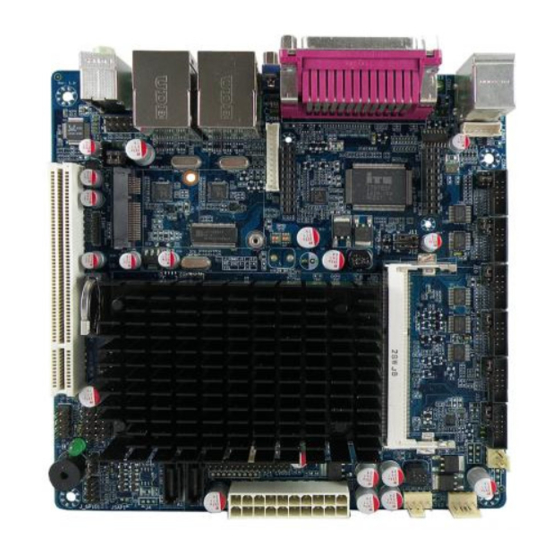
Page 6: Chapter 2 H/W Information
Chapter 2 H/W Information This chapter describes the installation of AMB-D255T3. At first, it shows the Function diagram and the layout of AMB-D255T3. It then describes the unpacking information which you should read carefully, as well as the jumper/switch settings for the AMB-D255T3 configuration. -
Page 7: Headers And Jumper Settings
2.2. Headers and Jumper Settings... - Page 8 Clear CMOS jumper F_PANEL1 COM5 control jumper Front panel pin header Note. AMB-D255T3 doesn’t design SATA power connector on the board. Please use the power supply with SATA power connector for SATA device. 2 ~ 7. COM1~6 Headers(5*2 Pin 2.00mm) Location...
- Page 9 J7 * J10 * J_COM3 J13 * J_COM4 J14 * J_COM5 J15 * J_COM6 Notes. These signals are depend on relevant Jumpers (e.g. Pin1 of J_COM1 depends on J6 Jumper), to find more details, check the following table (Location 8~13 & 27~28). Notes.
- Page 10 9. COM2 Control Jumper(3*2 Pin 2.00mm) Location Jumper Setting Function 1-3(Default) Pin1: DCD Pin1: + 5V Pin9: + 12V 4-6(Default) Pin9: RI 10. COM3 Control Jumpers(4*1 Pin 2.00mm) Location Jumper Setting Function 1-2(Default) Pin1: N/C Pin1: + 5V Pin1: + 12V 11.
- Page 11 14. System Fan Connector(3*1 Pin 2.54mm) Location Connector Definition Definition + 12V SYS_FAN1 15. CPU Fan Connector(4*1 Pin 2.54mm) Location Connector Definition Definition + 12V CPU_FAN1 FAN Speed Detection FAN Speed Control 16. LVDS Backlight Control Header(5*1 Pin 2.00mm) Location Header Definition Definition...
- Page 12 Notes. VCC could be 3.3V (default) or 5V by setting the LVDS VCC Selection Jumper (LVDS_P2, Location 21). 21. LVDS VCC Selection Jumper(3*2 Pin 2.54mm) Location Jumper Setting Function 1-2(Default) + 3.3V LVDS_P2 + 5V 22. GPIO Header(5*2 Pin 2.00mm) Location Header Definition...
- Page 13 23. CMOS Clear Jumper(3*1 Pin 2.54mm) Location Jumper Setting Function 1-2(Default) Normal JCMOS1 Clear CMOS 24. Front Panel Header(5*2 Pin 2.54mm) Location Header Definition Definition HD LED+ Power LED+ HD LED- Power LED- F_PANEL1 RESET- PWR+ RESET+ PWR- 25. Front USB Headers(5*2 Pin 2.54mm) Location Header Definition...
-
Page 14: Chapter 3 Bios Settings
Chapter 3 BIOS Settings This chapter describes the BIOS menu displays and explains how to perform common tasks needed to get the system up and running. It also gives detailed explanation of the elements found in each of the BIOS menus. The following topics are covered: ... -
Page 15: Main Setup
3.1. Main Setup Once you enter the AMI Setup Utility, the Main menu will appear on the screen. Use the arrow keys to highlight the item and then use the <Pg Up> <Pg Dn> keys to select the value you want in each item. Note: Listed at the bottom of the menu are the control keys. - Page 16 This item displays the motherboard model name and Motherboard Model version This item displays the date and time of building BIOS Build Date & Time System Date Set the date. Use Tab to switch between Date elements System Time Set the time. Use Tab to switch between Time elements Access Level This item displays the level of users...
-
Page 17: Advanced Setup
3.2. Advanced Setup Option Choice Description This item enable computer to wake on under specified Power On conditions. CPU Configuration This item displays the CPU configuration parameters. IDE Configuration This item displays the IDE devices configuration. USB Configuration This item displays the USB configuration parameters. This item displays the system super I/O chip configuration Super I/O parameters. -
Page 18: Power On Setup
3.2.1. Power On Setup Option Choice Description PowerOn after Power On, Power This item defines the AC power state when power is PowerFail Fail, Last Status re-applied after a power failure. Resume By Alarm Disabled, Enabled This item defines the computer will wake on by time setting. -
Page 19: Cpu Configuration Setup
3.2.2. CPU Configuration Setup Option Choice Description Processor Type This item displays the CPU type EMT64 This item displays it can support EMT64. Processor Speed This item displays the CPU speed. This item displays the System Bus speed. System Bus Speed Ratio Status This item displays the ratio status. - Page 20 System Bus Speed This item displays the System Bus speed. This item displays the CPU stepping Processor Stepping Microcode Revision This item displays the microcode revision L1 Cache RAM This item displays the L1 cache ram size. L2 Cache RAM This item displays the L2 cache ram size.
-
Page 21: Ide Configuration Setup
3.2.3. IDE Configuration Setup Option Choice Description SATA Port0 This item displays the SATA port0 device. SATA Port1 This item displays the SATA port1 device. SATA Controller Enabled, Disabled Enable or disable support for SATA device. IDE, AHCI This item defines the configuration of SATA controller Configure SATA as... -
Page 22: Usb Configuration Setup
3.2.4. USB Configuration Setup Option Choice Description USB Device This item displays the USB devices connected to system. Enabled, Disabled, Legacy USB Enable or disable support for legacy USB. Support Auto EHCI Hand-off Enabled, Disabled Enable or disable support for EHCI Hand-off. USB Mass Storage Enabled, Disabled Enable or disable support for USB Mass Storage Driver. -
Page 23: Super I/O Setup
3.2.5. Super I/O Setup Option Choice Description Super I/O Chip This item displays the Super I/O model name. COM1 This item displays the COM1 parameters. COM2 This item displays the COM2 parameters. This item displays the COM3 parameters. COM3 COM4 This item displays the COM4 parameters. - Page 24 COM6 This item displays the COM6 parameters. This item displays the LPT parameters.
- Page 25 3.2.5.1. COM1 Setup Option Choice Description Serial Port Enabled, Disabled Enable or disable support for COM1 This item displays the IO address and IRQ of COM1 Device Setting...
- Page 26 3.2.5.2. COM2 Setup Option Choice Description Serial Port Enabled, Disabled Enable or disable support for COM2 This item displays the IO address and IRQ of COM2 Device Setting...
- Page 27 3.2.5.3 COM3 Setup Option Choice Description Serial Port Enabled, Disabled Enable or disable support for COM3 This item displays the IO address and IRQ of Device Setting COM3...
- Page 28 3.2.5.4 COM4 Setup Option Choice Description Serial Port Enabled, Disabled Enable or disable support for COM4 This item displays the IO address and IRQ of Device Setting COM4...
- Page 29 3.2.5.5. COM5 Setup Option Choice Description Serial Port Enabled, Disabled Enable or disable support for COM5 This item displays the IO address and IRQ of Device Setting COM5...
- Page 30 3.2.5.6. COM6 Setup Option Choice Description Serial Port Enabled, Disabled Enable or disable support for COM6 This item displays the IO address and IRQ of Device Setting COM6...
- Page 31 3.2.5.7. LPT Setup Option Choice Description Parallel Port Enabled, Disabled Enabled or disabled the support of LPT port This item displays the IO address and IRQ of Device Settings LPT port STD Printer Mode, SPP Mode, EPP-1.9 and SPP Mode, EPP-1.7 and SPP Change the LPT port mode.
-
Page 32: Chipset Setup
3.3. Chipset Setup Option Choice Description Host Bridge This item displays the Host Bridge parameters. This item displays the South Bridge parameters. South Bridge... -
Page 33: Host Bridge Setup
3.3.1 Host Bridge Setup Option Choice Description Graphic Configuration This item sets the display device configuration. Memory Frequency This item displays the memory frequency. This item displays the total memory size. Total Memory DIMM0 This item displays the memory of DIMM0. DIMM1 This item displays the memory of DIMM1. - Page 34 3.3.1.1. Graphic Configuration Setup Option Choice Description VGA only, Select the video device which will be activated during IGFX – Boot Type LVDS only, HDMI POST. only, Disabled, Int-LVDS, Select the way to active LVDS Active LVDS VBIOS Default, 800x480 18bit, 800x600 18bit, 1024x600 18bit, LVDS Panel Type...
-
Page 35: South Bridge Setup
3.3.2. South Bridge Setup Option Choice Description Intel IO Controller This item displays the IO controller Hub parameter. PCI Express Port0 This item displays the PCI Express Port0 parameter. PCI Express Port1 This item displays the PCI Express Port1 parameter. PCI Express Port2 This item displays the PCI Express Port2 parameter. - Page 36 3.3.2.1. Intel IO Controller Hub Setup Option Choice Description Disabled, HD Audio Enabled or disabled the Azalia controller Azalia Controller By Ports, By Select USB Mode Select the USB mode to control USB ports Controller Disabled, 1 USB Ports, 2 USB Ports, USB Function 3 USB Ports, 4 USB Select the numbers of USB ports...
- Page 37 3.3.2.2. PCI Express Port 0 Setup Option Choice Description Enabled, Disabled Enabled or disabled the PCI Express Port 0 PCI Express Port 0...
- Page 38 3.3.2.3. PCI Express Port 1 Setup Option Choice Description Enabled, Disabled, Enabled or disabled the PCI Express Port 1 PCI Express Port 1 Auto...
- Page 39 3.3.2.4. PCI Express Port 2 Setup Option Choice Description Enabled, Disabled, Enabled or disabled the PCI Express Port 2 PCI Express Port 2 Auto...
- Page 40 3.3.2.5. PCI Express Port 3 Setup Option Choice Description Enabled, Disabled, Enabled or disabled the PCI Express Port 3 PCI Express Port 3 Auto...
-
Page 41: Boot Setup
3.4. Boot Setup Option Choice Description Setup Prompt Number of seconds to wait for setup activation key. Timeout Bootup NumLock On, Off Select the Keyboard NumLock state. State Fullscreen Logo Enabled, Disabled Enabled or disabled the fullscreen logo support. -
Page 42: Security Setup
3.5. Security Setup Option Choice Description Administrator Set the administrator password Password User Password Set the user password... -
Page 43: Save & Exit Setup
3.6. Save & Exit Setup Option Choice Description Save and Reset Yes, No Reset the system after saving the changes. Save Changes Yes, No Save changes done so far to any of the setup options. Discard and Reset Yes, No Reset the system without saving any changes. - Page 44 Yes, No Restore and load default settings for all the setup options. Restore Defaults Save as User Yes, No Save changes done so far as user default. Defaults Restore User Yes, No Restore user default settings for all the setup options Defaults...
Need help?
Do you have a question about the AMB-D255T3 and is the answer not in the manual?
Questions and answers