Table of Contents
Advertisement
Quick Links
Advertisement
Table of Contents

Related Manuals for Acrosser Technology AMB-IH61T3


Summary of Contents for Acrosser Technology AMB-IH61T3
- Page 1 AMB-IH61T3 Board User Manual...
- Page 2 Trademarks AMB-IH61T3 is a registered trademark of Acrosser; other product names mentioned herein are used for identification purposes only and may be trademarks and/or registered trademarks of their respective companies.
-
Page 3: Table Of Contents
Table of Contents Chapter 1 Introduction ............. 4 1.1. Specifications..................... 4 1.2. Package Contents ..................6 Chapter 2 H/W Information ............7 2.1. Mainboard illustration ................7 2.2. Headers and Jumper Settings ..............9 Chapter 3 BIOS Settings ............15 3.1. -
Page 4: Chapter 1 Introduction
Chapter 1 Introduction AMB-IH61T3 with Intel Pentium/Core i3/i5/i7 processor is a multi-function Industrial main-board, which is suitable for using in all kind of applications. Besides it basic I/O ports like VGA, USB, COM. LAN, and GPIO, it can expand to 10 x COM ports. - Page 5 Dimension 170 x 170mm Notes: [1]: Due to the restriction of Windows 32 bit OS, when applied more than 4G memory, 32 bit OS may detect less than actual size. [2]: COM3 can be RS232 or RS485 by setting jumpers. [3]: It is recommended to use CPUs those TDP no higher than 77W.
-
Page 6: Package Contents
1.2. Package Contents Check if the following items are included in the package. 1 x AMB-H61T3 main board 1 x Quick Manual 1 x Utility CD 1 x SATA Cable 1 x DB9 cable for 1 COM port ... -
Page 7: Chapter 2 H/W Information
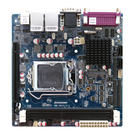
Chapter 2 H/W Information This chapter describes the AMB-IH61T3 jumper and switch settings. 2.1. Mainboard illustration ATX2 Power Supply Connector ATX1 Power Supply Connector Debug Header SATA Connector DIMM Slot Mini PCI-E Slot CPU Socket PCI-E x 16 Slot... - Page 8 LPT Connector PS/2 Connector COM Connector VGA1 Connector LAN Connectors USB Connectors Audio Connector VGA2 Connector Note. It can not use USB Hub with power adaptor that connects to USB port.
-
Page 9: Headers And Jumper Settings
2.2. Headers and Jumper Settings COM3~6 Header Audio Header LVDS Backlight Control Header COM2 Header CPU FAN Connector RS-485 Header COM3 Signal Selection Jumpers Front USB Headers COM7~10 Headers System FAN Connector CMOS Clear Jumper Front Panel Header LVDS VDD Selection Jumper LVDS Signal Header GPIO Header... - Page 10 [1] COM3-6 Headers(20*2 Pin 2.00 mm) Location Header Definition Definition COM3_DCD COM3_RXD COM3_TXD COM3_DTR COM3_DSR COM3_RTS COM3_CTS COM3_RI COM4_DCD COM4_RXD COM4_TXD COM4_DTR COM4_DSR COM4_RTS COM4_CTS COM4_RI J_COM3-6 COM5_DCD COM5_RXD COM5_TXD COM5_DTR COM5_DSR COM5_RTS COM5_CTS COM5_RI COM6_DCD COM6_RXD COM6_TXD COM6_DTR COM6_DSR COM6_RTS COM6_CTS COM6_RI...
- Page 11 [3] COM3 Signal selection Jumpers (3*1 Pin 2.0mm) Location Jumper Setting Function RS232 RS485 [4] System Fan Connector (3*1 Pin 2.54 mm) Location Connector Definition Definition +12V SYS_FAN FAN TAC [5] Front Panel Header(5*2 Pin 2.54 mm) Location Header Definition Definition HD LED+ Power LED+...
- Page 12 [7] Audio Header(5*2 Pin 2.54 mm) Location Header Definition Definition FRONT_MIC_L FRONT_MIC_R + 3.3 V F_AUDIO1 FRONT_OUT_R RRONT_Jack Detect FRONT_OUT_L [8] CPU Fan Connector (4*1 Pin 2.54 mm) Location Connector Definition Definition +12V CPU_FAN FAN TAC FAN PWM [9] Front USB Headers (5*2 Pin 2.54mm) Location Header Definition...
- Page 13 [11] LVDS VDD selection Jumper(3*2 Pin 2.54 mm) Locatio Jumper Setting Function VDD=12V VDD=3.3V LVDS_P1 2-4 or 4-6 VDD=5V [12] LVDS Signal Header(15*2 Pin 2.00 mm) Location Header Definition Definition VDD* VDD* VDD* DA1- DA1+ DA2- DA2+ DA3- DA3+ LVDS1 CLKA- CLKA+ DA4-...
- Page 14 [14] RS485 Header (COM3, 3*1 Pin 2.54mm) Location Header Definition Definition RS485- RS485+ [15] COM7-10Headers(20*2 Pin 2.00 mm) Location Header Definition Definition COM7_DCD COM7_RXD COM7_TXD COM7_DTR COM7_DSR COM7_RTS COM7_CTS COM7_RI COM8_DCD COM8_RXD COM8_TXD COM8_DTR COM8_DSR COM8_RTS COM8_CTS COM8_RI J_COM7-10 COM9_DCD COM9_RXD COM9_TXD COM9_DTR...
-
Page 15: Chapter 3 Bios Settings
Chapter 3 BIOS Settings This chapter describes the BIOS menu displays and explains how to perform common tasks needed to get the system up and running. It also gives detailed explanation of the elements found in each of the BIOS menus. The following topics are covered: Main Setup ... -
Page 16: Main Setup
3.1. Main Setup Once you enter the AMI Setup Utility, the Main menu will appear on the screen. Use the arrow keys to highlight the item and then use the < + > < - > keys to select the value you want in each item. - Page 17 System Date Set the date. Use Tab to switch between Date elements. System Time Set the time. Use Tab to switch between Time elements. Access Level This item displays the level of users.
-
Page 18: Advanced Setup
3.2. Advanced Setup Option Choice Description ACPI Settings This item display system ACPI parameters. Power On This item display system power on settings after power fail. LVDS Configuration This item display LVDS panel parameters. CPU Configuration This item displays the CPU configuration parameters. SATA Configuration This item displays the SATA devices configuration. -
Page 19: Acpi Settings Setup
3.2.1. ACPI Settings Setup Option Choice Description ACPI Auto Disabled, Enables or disables BIOS ACPI Configuration. Configuration Enabled Disabled, Enable Hibernation Enables or disables Hibernation mode. Enabled Disabled, ACPI Sleep State Set ACPI sleep state is disabled or S1 mode only. S1only... -
Page 20: Power On Setup
3.2.2. Power On Setup Option Choice Description PowerOn after Power On, Power This item defines the AC power state when power is PowerFail Off, Last Status re-applied after a power failure. -
Page 21: Lvds Configuration Setup
3.2.3. LVDS Configuration Setup... -
Page 22: Cpu Configuration Setup
3.2.4. CPU Configuration Setup It display the CPU configuration information. -
Page 23: Sata Configuration Setup
3.2.5. SATA Configuration Setup Option Choice Description SATA Controller Enabled, Disabled Enable or disable support for SATA device. SATA Mode This item defines the configuration of SATA controller Selection Serial ATA Port 1/2 This item displays the SATA port 1/2 device. -
Page 24: Super I/O Setup
3.2.6. Super I/O Setup Option Choice Description Super I/O Chip This item displays the Super I/O model name. COM1 ~ COM6 This item displays the COM1 ~ COM6 parameters. This item displays the LPT parameters. - Page 25 3.2.6.1. COM1 ~ COM6 Setup Option Choice Description Serial Port Enabled, Disabled Enable or disable support for COM1~COM6 Device Setting This item displays the IO address and IRQ of COM1~COM6 Change Settings Auto, other settings This item selects IO port and IRQ parameters.
- Page 26 3.2.6.2. LPT Setup Option Choice Description Parallel Port Enabled, Disabled Enabled or disabled the support of LPT port This item displays the IO address and IRQ of Device Settings LPT port Change Settings Auto, other settings This item select IO port and IRQ parameters. STD Printer Mode, SPP Mode, EPP-1.9 and SPP Mode, Device Mode...
-
Page 27: Hardware Monitor Setup
3.2.7. Hardware Monitor Setup Remark: After you clear CMOS info, please load optimized default CMOS setting and reboot your system. -
Page 28: Com7/8/9/10 Configuration Setup
3.2.8. COM7/8/9/10 Configuration Setup Option Choice Description Super I/O Chip This item displays the Super I/O model name. COM7 ~ COM10 This item displays the COM7 ~ COM10 parameters. - Page 29 3.2.8.1. COM7~COM10 Setup Option Choice Description Serial Port Enabled, Disabled Enable or disable support for COM7~COM10 Device Setting This item displays the IO address and IRQ of COM7~COM10 Change Settings Auto, other settings This item selects IO port and IRQ parameters.
-
Page 30: Chipset Setup
3.3. Chipset Setup Option Choice Description PCH-IO Configuration This item displays the PCH parameters. System Agent This item displays the System Agent parameters. Configuration... -
Page 31: Pch-Io Configuration Setup
3.3.1 PCH-IO Configuration Setup... - Page 32 3.3.1.1. PCI Express Configuration Setup Option Choice Description PCI Express Port 1 This item displays the PCI Express Port 1 parameter. PCI Express Port 2 This item displays the PCI Express Port 2 parameter. PCI Express Port 3 This item displays the PCI Express Port 3 parameter.
- Page 33 Option Choice Description PCI Express Port 1 Enabled, Disabled Enabled or disabled the PCI Express Port 1 Set the ASPM Level: Disabled, Force L0, Force L0s - Force all links to L0s State ASPM Support Auto AUTO - BIOS auto configure DISABLED - Disable ASPM...
- Page 34 3.3.1.2. USB Configuration Setup Option Choice Description EHCI1 Enabled, Disabled Enabled or disabled the EHCI Port 1 EHCI2 Enabled, Disabled Enabled or disabled the EHCI Port 2...
- Page 35 3.3.1.3. PCH Azalia Configuration Setup Option Choice Description Enabled, Disabled, Azalia Enabled or disabled the Azalia controller. Auto...
-
Page 36: System Agent Configuration Setup
3.3.2. System Agent Configuration Setup Option Choice Description Graphics This item displays the graphics parameter. Configuration Memory This item displays the memory parameter. Configuration... - Page 37 3.3.2.1. Graphics Configuration Setup Option Choice Description Select which of IGFX/PEG/PCI Graphics Primary Display Auto / IGFX / PEG device should be Primary Display 0r select SG for Switchable Gfx. GTT Size 1MB / 2MB Select the GTT Size Aperture Size 128MB / 256MB / 512MB Select the Aperture Size 32M / 64M / 96M / 128M /...
- Page 38 3.3.2.2. Memory Configuration Setup...
-
Page 39: Boot Setup
3.4. Boot Setup Option Choice Description Bootup NumLock On, Off Select the Keyboard NumLock state. State Full Screen Logo Enabled, Disabled Enabled or disabled the fullscreen logo support. Enables or disables boot with initialization of a minimal Fast Boot Disabled / Enabled set of devices required to launch active boot option. -
Page 40: Security Setup
3.5. Security Setup Option Choice Description Administrator Set the administrator password Password User Password Set the user password Secure Boot flow control. Secure Boot is possible only if Secure Boot Enabled, Disabled System runs in User Mode. Default is enabled. Secure Boot Mode Standard, Custom Select Secure Boot mode. -
Page 41: Save & Exit Setup
3.6. Save & Exit Setup option Choice Description Save Changes and Pressing <Enter> on this item for Exit system setup after saving the changes. Exit save changes and exit. Discard Changes and Pressing <Enter> on this item for Exit system setup without saving any changes. Exit discard changes and exit. - Page 42 Pressing <Enter> on this item for Discard Changes and confirmation: reset without save Reset system setup without saving any changes. Reset changes Pressing <Enter> on this item for Save Changes done so far to any of the setup Save Changes confirmation: save previous options.
-
Page 43: Faq
Does my system support Fedora and Linux basic? The system has been verified with Fedora 17 and Linux basic. When you install OS, please plug your monitor into VGA2 connector. VGA2 (blue color) - Page 44 Acrosser service contact info: We deeply appreciate you purchase Acrosser products. If you have any questions or problems about Acrosser products, the following is the suggested procedures: We will answer your questions a.s.a.p. 1) Describe your info and Acrosser system info Your company name: _____________ Your contact info: ____________________ &...
- Page 45 Acrosser Headquarters 新北市三重區重新路五段609巷12號10樓 10F., No.12, Lane 609, Sec. 5, Chongsin Rd., Sanchong District, New Taipei City 241, Taiwan, R.O.C. TEL: +886-(0)2-2 9999 000 FAX: +886-(0)2-2999-2887 Acrosser Taichung Office 台中市南屯區河南路四段162號12樓之6 12-6, No.162, Sec. 4, Henan Rd., Nantun Dist., Taichung City 408, Taiwan R.O.C. TEL: +886-(0)4-2251-0659 FAX: +886-(0)4-2254-6079 Acrosser China Subsidiary...
Need help?
Do you have a question about the AMB-IH61T3 and is the answer not in the manual?
Questions and answers