Table of Contents
Advertisement
Quick Links
Advertisement
Table of Contents

Related Manuals for Acrosser Technology AR-B6003


Summary of Contents for Acrosser Technology AR-B6003
- Page 1 AR-B6003 Board User Manual...
- Page 2 Trademarks AR-B6003 is a registered trademarks of Acrosser; IBM PC is a registered trademark of the International Business Machines Corporation; Pentium is a registered trademark of Intel Technologies Inc; Award is a registered trademark of Award Software International Inc;...
-
Page 3: Table Of Contents
Table of Contents Chapter 1 Introduction ....................4 1.1 Specifications....................4 1.2 Package Contents .....................5 1.3 Block Diagram ....................5 Chapter 2 H/W Information ...................6 2.1 Mainboard illustration (Top Side)..............6 2.2 Locations of IO ports & Jumper Setting Definition (Top Side).......8 Chapter 3 BIOS Settings....................17 3.1 Main Setup .....................18 3.2 Advanced Chipset Setup ................21 3.3 PnP/PCI Setup....................23... -
Page 4: Chapter 1 Introduction
Chapter 1 Introduction AR-B6003 is an embedded SBC that is designed for rugged environment. Without compromise the performance, it equipped with the most advanced ATOM D525 (dual cores) or D425 (single core) CPU and up to 4GB of DDR3 memory. Customers can select suitable CPU and memory size to get the best performance/price ratio. -
Page 5: Package Contents
1.2 Package Contents Check if the following items are included in the package. Quick Manual AR-B6003 board 1 x Software Utility CD 1.3 Block Diagram... -
Page 6: Chapter 2 H/W Information
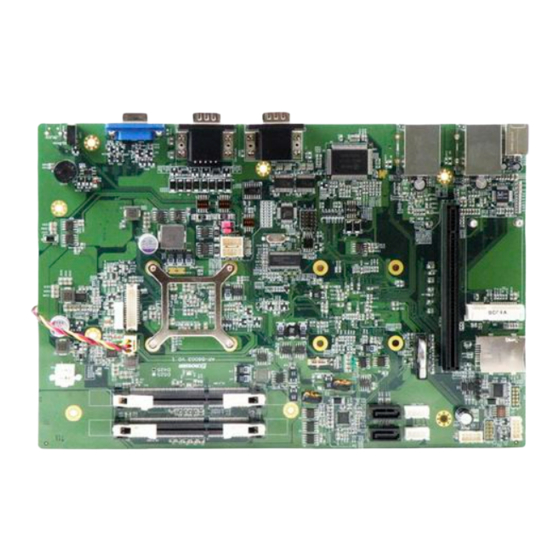
Chapter 2 H/W Information This chapter describes the installation of AR-B6003. At first, it shows the Function diagram and the layout of AR-B6003. It then describes the unpacking information which you should read carefully, as well as the jumper/switch settings for the AR-B6003 configuration. - Page 7 Mainboard illustration (Bottom Side) In tel Atom Pineview D425/D525 CPU System RTC battery socket PCIE_R1 Intel ICH8M PCI-E & PCI riser card socket CN_DIMM2 204-Pin DDR3 Socket CN_DIMM1 204-Pin DDR3 Socket...
-
Page 8: Locations Of Io Ports & Jumper Setting Definition (Top Side)
2.2 Locations of IO ports & Jumper Setting Definition (Top Side) - Page 9 Locations Of IO Ports & Jumper Setting Definition (Bottom Side)
- Page 10 FPIO1 LED1 ATX Power on/off & Reset switch 2 in 1 LED for Power & HDD LED. CF CARD SOCKET button connector. PWR1 SIM1 SIM card Holder Connector for 0932V power board CN_RS232_1 MINIPCIE1 Pin Header for COM2 use RS-232 Mini-PCI Express Card connector function CN_RS422_485_1...
-
Page 11: Connectors And Jumper Settings
2.2.1 Connectors and Jumper settings 1. FPIO1 2. SIM1 Connector FPIO1 Connector Pin1-2 ATX Power on/off SIM Card Holder switch button Connects to 3.5G Cell phone SIM Card. Pin5-6 System Reset switch button 3. MINIPCIE1 ( Mini-PCIe 4. AUDIO1 Connector ) Audio Jack Mini-PCIe x1 Lime: Line Out... - Page 12 8. COM3_COM4 ( for COM3,COM4 use ) 9. SW2 ( RS-422,RS-485 function select ) SW2, DIP Switch For RS-422,RS-485 Function select(Default: All OFF For SIGNAL RS-232) RS-422 setting: SOUT RS-485 setting: 10. SW4 ( RS-422/485 TX Terminator resistor 11 GPIO_COM1 (For COM1 RS-232, selection ) External GPIO control) SW4 DIP Switch...
- Page 13 12, SW5 (RS-422 RX terminator resistor 13. VGA1 (D-SUB 15 pin selection) Connector) SW5 DIP Switch For RS-422 RX Terminator resistor selection) (Default: all OFF) VGA1 D-SUB 15 pin For CRT Monitor 14. LED1 15 PWR1 (For 0932V power board use only Connector) Pin 1 Green: Power ON LED.
- Page 14 16. CN_RS232_1 18. LVDS1 (30 pin DF13 Connector). 17. CN_RS422_485_1 (For COM2 Function select). CN_RS232_1: For RS-232 Function SIGNAL LVDS1: 30 pin DF13 connector SOUT CN_RS422_485_1: For RS-422,RS-485 Function SIGNAL 485_422_TX+ 485_422_TX- 422_RX2- 422_RX2+...
- Page 15 19.LCDPWR1 (LCD Power Connector) 20. CN4 (ATX12V Power Input) Pin 1 Pin 2 Pin 3 21. CCMOS1. 22. SATA1, SATA2 (SATA device connector #1 and #2). To connect SATA device: 1.Attach either end of the signal cable to the SATA connector on motherboard.
- Page 16 23. SATA_PWR1, SATA_PWR2 24. FP_USB1,FP_USB2 SATA_PWR1, SATA_PWR2 SATA Device Po wer Conn ector SIGNAL +12V VCC3 VCC5 26. BH1 (CR2032 Battery Holder). 27. CPUFAN1 (CPU FAN connector 1). CMOS Backup Battery: An onboard battery saves the CMOS memory to keep the BIOS information stays on even after disconnected your SIGNAL system with power source.
-
Page 17: Chapter 3 Bios Settings
Chapter 3 BIOS Settings This chapter describes the BIOS menu displays and explains how to perform common tasks needed to get the system up and running. It also gives detailed explanation of the elements found in each of the BIOS menus. The following topics are covered: ... -
Page 18: Main Setup
3.1 Main Setup Once you enter the Award BIOS™ CMOS Setup Utility, the Main Menu will appear on the screen. Use the arrow keys to highlight the item and then use the <Pg Up> <Pg Dn> keys to select the value you want in each item. Note: Listed at the bottom of the menu are the control keys. - Page 19 All Errors, No Errors, Select the situation in which you want the BIOS to stop the Halt On All but POST process and notify you. keyboard(Default) "The POST of the BIOS will determine the amount of base (or conventional) memory installed in the system. The value of the base memory is typically 512K for sy stems Base Memory...
- Page 20 Option Choice Description IDE HDD Enter To auto-detect the CF's size, head…. On this channel Auto-Detection Auto Allows BIOS to automatically detect IDE/SATA devices during POST None IDE Channel 0 None Select this if no I DE/SATA devices are used and the Auto(Default) Master ystem will skip the automatic detection step and allow...
-
Page 21: Advanced Chipset Setup
3.2 Advanced Chipset Setup This section consists of configuration entries that allow you improve your system performance, or modify some system features ccording to your preference. Some entries are required and reserved by the board’s design. Note: Listed at the bottom of the menu are the control keys. If you need any elp with the item fields, you can press the <F1>... - Page 22 Enables APIC (Advanced Programmable Interrupt APIC Mode Enabl ed(De fault) Controller) functionality. nboard(Default Auto detect VGA output from onboard or output from PCI-E it Display First add-on card when the PCI-E card installed. Auto(Default) System should auto detect which monitor is connecting, t Display then select the either CRT or LVDS output only when both of...
-
Page 23: Pnp/Pci Setup
3.3 PnP/PCI Setup The option configures the PCI bus system. All PCI bus system on the system use INT#, thus all installed PCI cards must be set to this value. Note: Listed at the bottom of the m enu are the control keys. If you need any help with the item fields, you can press the <F1>... -
Page 24: Peripherals Setup
3.4 Peripherals Setup This option controls the configuration of the board’s chipset. Control keys for this screen are the same as for the previous screen Note: Listed at the bottom of the menu are the control keys. If you need any help with the ite m fields, you can... - Page 25 Disabled Select an ad dress and the corresp onding Onboar d Serial Port 4 4F8/IRQ interrupt for eac h serial port. 4E8/IRQ10(Default) Select Enabl ed if your system contains a Universal Serial Bus (USB) 2.0 USB Device Setting Enter controller and you have USB peripherals The integrated peripheral controller OnChip IDE Device...
- Page 26 Option Choice Description IDE DMA transfer Disable Enable or disable IDE DMA transfer access. access Enable(Default) To select SATA Mode to IDE and AHCI Mode. Select [IDE] if IDE(Default) you want to have SATA function as IDE. Select [AHCI] for SATA Mode Advanced Host Controller Interface (AHCI) feature, with AHCI...
-
Page 27: Pc Health Setup
3.5 PC Health Setup This section shows the parameters in determining the PC Health Status. These parameters include temperatures, fan speeds, and voltages. Note: Listed at the bottom of the menu are the control keys. If you need any help with the item fields, you can press the <F1> key, and it will display the relevant information. -
Page 28: Boot Setup
3.6 Boot setup This option allows user to select sequence/priority of boot device(s) and Boot from LAN. Note: Listed at the bottom of the menu are the control keys. If you need any help with the item fields, you can press the <F1> key, and it will display the relevant information. - Page 29 Disabled The BIOS attempts to load the operating system from the Boot Other Device Enable(Default) devices in the sequence selected in these items. Hard Disk Boot These fields set the Boot Priority for each Hard Disk. Priority This item allows you to set the priority for hard disk boot. It shows the current hard disks used in your system.
-
Page 30: Exit Setup
3.7 Exit Setup This option is used to exit the BIOS main menu and change password. Note: Listed at the bottom of the menu are the control keys. If you need any help with the item fields, you can press the <F1> key, and it will display the relevant information. - Page 31 Defaults (Y/N)? N Pressing <Enter> on this item for Exit This allows you to exit Setup without storing any changes in confirmation: Without CMOS. The previous selections remain in effect. This shall exit Saving the Setup utility and restart your computer. Quit without saving (Y/N)? Y When a password has been enabled, you will be prompted to...
-
Page 32: Chapter 4 Function Description
Chapter 4 Function Description 4.1 DC Power input connection AR-B6003 needs +12V to power the board. If you use standard ATX PSU, you need to connect COM/GND with PS_ON# signal (green wire in the ATX connector, pin 16). Else, standard ATX PSU will not generate power to 4 pin... -
Page 33: Digital Inputs
4.2 Digital Inputs There are 4 clamped diode protection digital inputs on GPIO_COM1 connector. You can read the status of any input through the software API. These digital inputs are general purpose input. You can define their purpose for any digital input function. -
Page 34: Digital Outputs
4.3 Digital Outputs There are 4 clamped diode protection digital outputs on GPIO_COM1 connector. You can control the output status of these digital outputs through the software API. The four digital outputs are capable sink maximum 500 mA current for each channel and maximum output voltage is 12V. The output reference voltage of device, please connect to GPIO #VCC12V(Pin15). -
Page 35: Watchdog Timer
4.5 RS-232 Ports There are three RS-232 ports on the AR-B6003. The COM1/COM3/COM4 are connected through a male D-Sub 9-pin connector for serial communication. The COM2 is connected through a cable. Users need to plug into RS-232 or RS-422/485 connector. - Page 36 Pin number RS-232 male CN_RS232_1: For RS-232 Function SIGNAL SOUT CN_RS422_485_1: For RS-422, RS-485 SIGNAL 485_422_TX+ 485_422_TX- 422_RX2- 422_RX2+...
-
Page 37: Serial Ata (Sata)
4.6 Serial ATA (SATA) There are 2 SATA 2.5 ports on the AR-B6003. There are also two SATA power connectors for the SATA hard disks. The SATA power cable is an optional accessory. If you need a SATA power connector, please contact your Acrosser sales representative for the quotation. -
Page 38: Chapter 5 Driver And Utility Installation
Chapter 5 Driver And Utility Installation 5.1 Driver CD Interface Introduction Acrosser provides the driver CD including the drivers, utilities, applications and documents. Once putting into optical driver, it will run automatically. The driver CD will also detect the MB information to see if they are matched. - Page 39 Click the item, all the drivers will be selected. Click the item, all selected items will be cancelled.
- Page 40 Click the “Install” icon to install the selected drivers. Click the item to browse the CD contents.
- Page 41 Click the icon to close the program.
- Page 42 5.1.2 Utility Page There is one utility for AR-B6003. The detailed information please refers to Software Programming Guide for how to use the API. Double click the “GPIO_Watchdog Setting Tool” to run the utility.
- Page 43 5.1.3 Application Page There is one application for Acrobat reader installing. Double click the “Acrobat Reader 9.2” to install the application.
- Page 44 5.1.4 Document Page This page will provide Acrosser board and system user manual. Please remember to install the Acrobat Reader before you read the manual. Double click the manual item to read the user manual.
- Page 45 Please install the Acrobat Reader when you see the message.
-
Page 46: Windows Xp 32Bit Driver Installation
5.2 Windows XP 32bit Driver Installation 5.2.1 Please put the driver disk to optical driver. The program will appear on the screen. Please click the “Select All” icon. - Page 47 5.2.2 Click the “Install” icon to install the drivers. 5.2.3 Finish the driver installation. Please click “Yes” to restart the system.
-
Page 48: Windows 7 32/64Bit Driver Installation
5.3 Windows 7 32/64bit Driver Installation 5.3.1 Please put the driver disk to optical driver. Then click the “Run setup.exe” to run the install program. - Page 49 5.3.2 The program will appear on the screen. Please click the “Select All” icon. 5.3.3 Click the “Install” icon to install the drivers.
- Page 50 5.3.4 Finish the driver installation. Please click “Yes” to restart the system.
-
Page 51: Chapter 6 Software Installation And Programming Guide
6.1 Introduction Overview of GPIO and Watchdog AR-B6003 provides both a GPIO interface and a Watchdog timer. Users can use the GPIO and Watchdog APIs to configure and to access the GPIO interface and the Watchdog timer. The GPIO has four input pins and four output pins. The Watchdog timer can be set to 1~255 seconds. -
Page 52: File Descriptions
3. main.c The source code of the utility. 4. Makefile On Windows platform: AR-B6003.h The header file of the APIs and macro definition. This header file is an aggregate header which includes APIs declarations and macros for GPIO, Watchdog. AR-B6003.lib The API library in static library format. -
Page 53: Api List And Descriptions
6.3 API List and Descriptions GPIO 1. Syntax: i32 getInChLevel( i32 channel, u8 *val ) Description: Get the value of GPIO Input and put the value at *val. Parameters: The parameter ‘channel’ indicates the GPIO Input pins to show. Users can use the macros GPI0, GPI1, GPI2, GPI3 to indicate the GPIO Input channel. - Page 54 Parameters: The parameter ‘channel’ indicates the GPIO Output pins to set. Users can use the macros GPO0, GPO1, GPO2, GPO3 to indicate the GPIO Output channels. The parameter ‘val’ indicate the value to be set to GPIO Output channel. The acceptable values are limited to 0 and 1. For example: /* Setting the GPIO Output channel 2 to 1 */ setOutChLevel( GPO2, 1 );...
- Page 55 Here is an example: If GPIO Output channel 0 and channel 2 are both 1. unsigned char ch; getOutChLevel( GPO0|GPO2, &ch ); The returned value of variable ‘ch’ is 0x5. Return Value: If the function gets the values successfully, it returns 0. If any error, it returns –1.
-
Page 56: Enable Testsigning On Windows 7 X64 System
6.4 Enable TESTSIGNING on Windows 7 X64 system In order that the APIs works correctly on the Windows 7 X64 system, users have to enable the boot configuration test-signing option before invoking any APIs. Please follow the steps listed below to turn on the test-signing flag: 1. - Page 57 3. Run the ‘bcdedit’ again without any option. A new item ‘testsigning’ is enabled. 4. Reboot the system.
Need help?
Do you have a question about the AR-B6003 and is the answer not in the manual?
Questions and answers