Advertisement
Quick Links
Advertisement

Related Manuals for Goblin SPEED


Summary of Contents for Goblin SPEED
- Page 2 Goblin SPEED Manual Release 1.0 -December 2013 SAB HELI DIVISION S.R.L. Via San Crispino, 47 47030 San Mauro Pascoli (FC) - ITALY...
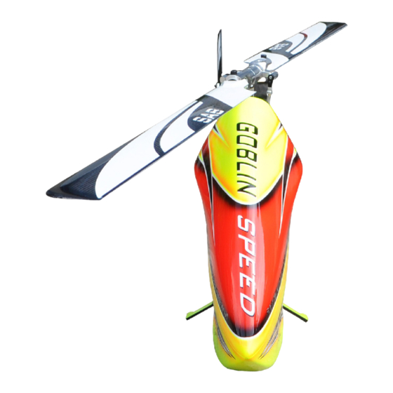
- Page 3 The Goblin Speed is the best compromise between a 3D helicopter and a full body, aerodynamically efficient, speed helicopter. The Goblin Speed incorporates all the best parts and components SAB Heli Division has to offer in order to support the most extreme power systems available in the market today.
- Page 4 *It is necessary that you know your radio system well. Check all functions of the transmitter before every flight. *The blades of the model rotate at a very high speed; be aware of the danger they pose and the damage they may cause.
- Page 5 *4mm T-Wrench Pinion shaft diameter 6/8mm *5.5mm Socket wrench (for M3 nuts) *8mm Hex fork wrench (for M5 nuts) *Speed controller: minimum 160A to be safe *Medium threadlocker (eg. Loctite 243) *Batteries: 12S-5000mAh or 14S-4500mAh *Strong retaining compound (eg. Loctite 648) *1 flybarless 3 axis control unit *Spray lubricant (eg.
- Page 6 Chapter 4, Carbon Frame The manufacturing process of the carbon parts often leaves micro-burrs and sharp edges. We recommend de-burring the edges to minimize 4-Carbon Frame the risks of electrical wire cuts, etc. Very important in red line zone. Copyright © 2013 - SAB Heli Division - All rights reserved Page 4...
- Page 7 Chapter 4, Carbon Frame Battery Support Assembly Socket Head Cap Screw M2.5x8mm (HC020-S) Stop Battery Plate (H0150-S) Battery Tray (H0002-S) Flat Head Cap Screw M2.5x5mm (HC128-S) Flat Head Cap Screw M2.5x5mm (HC128-S) Frame Spacer (H0003-S) Frame Spacer (H0003-S) Frame Spacer (H0003-S) Flat Head Cap Screw M2.5x5mm...
- Page 8 (HC62-S) (H0368-S) Main Frame 1 Finishing Washer M3 (H0354-S) (H0007-S) Socket Head Cap Screw M3x10mm (HC056-S) Frame Spacer (H0003-S) Landing Gear Mount Speed (H0374-S) Flat Head Cap Finishing Socket Head Cap Screw M3x8mm Washer M3 Screw M3x10mm (HC134-S) (H0007-S) (HC056-S)
- Page 9 Chapter 4, Carbon Frame Main Frame (H0354-S) Vertical ESC Support (H0368-S) Metrix Hex Nylon Nut M2.5 H0370 (HC200-S) Flat Head Cap Screws M3x8mm (HC134-S) Finishing Washer M2.5 (H0255-S) Socket Head Cap Finishing Washer M3 Screw M2.5x8mm (HC020-S) Socket Head Cap Socket Head Cap Screw M3x12mm Screw M3x10mm...
- Page 10 Chapter 5, Transmission Assembly 5 - Transmission Assembly Page 8 Copyright © 2013 - SAB Heli Division - All rights reserved...
- Page 11 Chapter 5, Transmission Assembly Flat Head Cap Screw M2.5x5mm (HC128-S) Bearing 24x6mm (HC426-S) Bearing Support Assembly (H0024-S) Socket Head Cap Screw M3x10mm (HC056-S) Socket Head Cap Screw M3x10mm Bearing 19x5mm (HC056-S) Servo Support (H0010-S) ..Socket Head Cap Screw Bearing 24x6mm M3x10mm ..
- Page 12 Chapter 5, Transmission Assembly 60T Pulley Assembly (H0171-S) Note 1: When you tighten the collar (H0121-S) on the main shaft, ensure there is no axial play. Push Bearing down the main shaft while pulling up the locking 15x4mm (HC420-S) collar. Tighten the screw M4x22 at this time. One Way Bearing 14x12mm Note 2:...
- Page 13 Chapter 5, Transmission Assembly Tail Belt Idler Assembly (H0174-S) Flanged Bearing 7x3mm (HC402-S) Tail Belt Idler Button Head Cap Screw M3x4mm (HC038-S) Main Structure Belt Tensioner Support Assembly 3 (H0174-S) Belt Tensioner Arm Assembly (H0174-S) Spring de 8 / df0.5 / LL8 (HC315-S) Belt Tensioner Arm Washer...
- Page 14 Chapter 5, Transmission Assembly Socket Head Cap Flanged Bearing Screw M3x8mm Metric Hex Nylon 13x5mm (HC050-S) Nut M5 (HC414-S) (HC218-S) Bearing Support (H0142-S) Lock H0142 after have locked Washer the motor.Motor shaft is requires 5.3x 15x1mm to optimize the centering. (HC188-S) H0142 can not be used with motor shaft 8mm.
- Page 15 Chapter 6, Head 6 - Main Rotor Page 13 Copyright © 2013 - SAB Heli Division - All rights reserved...
- Page 16 Chapter 6, Head Uniball Radius Arm... x2 Radius Arm ... x2 Center Hub Assembly Assembly Assembly Flanged Bearing Flanged Bearing Spindle 2.5x 6x2.5mm 7x3mm (H0079-S) (HC400-S) (HC402-S) Radius Arm (H0132-S) Damper Derlin (H0144-S) Oring (HA024) Center Hub Spacer Arm (H0135-S) 2.5x 4x6.3mm H0253 (H0132-S)
- Page 17 Chapter 7, Assembling The Modules Head HPS Assembly Metric Hex Socket Head Cap Nylon Nut M4 Screw M3x12mm (HC212-S) (HC062-S) Socket Head Cap Screw M3x12mm (HC062-S) Socket Head Cap Shoudered M4x24mm (HC111-S) Swashplate Assembly Socket Head Cap Screw M3x8mm (HC050-S) Carbon Frame Assembly Finishing Washer...
- Page 18 INSTALLATION OF SWASHPLATE SERVOS The linkage ball must be positioned between 17-19 mm out on the servo arm (figure 1). The 120° placement of the servos inside Goblin means the arms are difficult to access. For this reason it is advisable to ensure alignment of the servo arms (and sub trim set) before installation of the servos in the model (figure 2).
- Page 19 Chapter 8, Installation Of Swashplate Servos The wire for the front servo must be positioned here Head HPS Version Preliminary Setup Linkage Rod A Assembly ... x2 Adjust the linkage as shown. The linkage Rod A has thead right/left. Approx 75mm Turning, you can change the tracking without disconnecting the plastic ball link.
- Page 20 It is recommended to use wiring and connectors appropriate for the currents generated in a helicopter of this class. If you are using a head speed calculator which requires a main gear and pinion tooth count, use 214 teeth for the main gear (this takes into account the two stage reduction) and the tooth count of your pulley as the pinion count.
- Page 21 We recommend de-burring the edges of the carbon parts in areas where electrical wires run. ESC INSTALLATION The speed controller (ESC) is installed in the front of the helicopter. We recommend to use 6-8 mm connector and correct wires to support high current (>200A)
- Page 22 Chapter 10, Installation Of The ESC Figure 1: Shows the wiring which connects the receiver and ESC . If the BEC used is combined with the ESC, it is recommended to use a dual wire connection. Figure 2-3: Shows the installation of a 2S battery for the flight control system. Alternatively, a BEC could be placed in the same area.
- Page 23 Chapter 11, Installation Of The FBL Unit and RX FLYBARLESS CONTROL UNIT AND RX INSTALLATION It is possible to install any commercially available Flybarless control unit in the goblin. For Flybarless systems with a separate sensor, the sensor must be installed under the plate (Figure 1).
- Page 24 Chapter 12, Tail 7-Boom and Tail Page 22 Copyright © 2013 - SAB Heli Division - All rights reserved...
- Page 25 Chapter 12, Tail Tail Pitch Slider 01 (H0053-S) Tail Rotor Hub Assembly Tail Pitch Slider Assembly Flanged Bearing 12x3.5mm Spindle Shaft (HC418-S) (H0329-S) Oring Spacer (HC335-S) 8.1x 9.2x3.2mm Tail Shaft Uniball M3x3.5 (H0325-S) (H0065-S) Tail Pitch Slider 02 (H0053-S) Tail Pitch Slider 03 (H0053-S) Buttom Head Cap Note:...
- Page 26 Chapter 12, Tail Bell Crank Lever Assembly Tail Side Plate Assembly Socket Head Cap Screw M2.5x8mm Bell Crank Base (HC020-S) (H0058-S) Tail Side Plate (H0373-S) Washer 4x0.5mm Flanged Bearing 7x3mm (HC402-S) Spacer 4 x 9.6mm Flanged Bearing H0060 (H0059-S) Bush Bell Crank 13x5mm (H0059-S) (HC414-S)
-
Page 27: Tail Boom Assembly
Chapter 12, Tail Tail Boom Assembly Yellow Tail Boom (H0366-S) Orange Tail Boom (H0383-S) DETAIL A Attaching H0082-S to the boom: Pre-assemble the two boom spacers H0082-S with the M3x20 socket set screw. Insert into the boom tube completely done up. Center the holes, then unscrew until there is contact with the walls Lock everything with the adhesive. - Page 28 Chapter 12, Tail Tail Boom Assembly Socket Head Cap Screw M3x12mm (HC062-S) Finishing Washer M3 (H0007-S) Finishing Washer M3 Finishing Washer M3 (H0007-S) ..Socket Head Cap Screw Socket Head Cap Screw M3x12mm M3x12mm (HC062-S) ..Threaded Rod M2.5x40mm Threaded Rod M2.5x40mm (HC242-S) (HC242-S) Plastic Ball Link...
- Page 29 Chapter 12, Tail Servo Installation Tail Servo Assembly The distance between the 15-16mm axis and the ball must be between 15-16 mm Socket Head Cap Screw M2x6mm (HC004-S) Tail Servo Socket Head Cap Screw M2.5x12mm (HC026-S) Servo Spacer (H0075-S) Tail Servo Assembly Uniball M2 (H0064-S) Carbon Rod Assembly...
- Page 30 Chapter 13, Installation Of The Boom BOOM ASSEMBLY *Insert the tail boom assembly . *Lock the M8 nuts with the HA016 special tool supplied (Tray 2). *Firmly lock the lateral srews M3x12. Use Loctile for this screw and make sure you remain tight. *Assemble the H0038 carbon security plate .
- Page 31 NOTE. To disassemble the tail boom it is possible to remove the pulley H0101-S without loosening the tail unit. Remove the locking screw and pull down. CANOPY The Goblin Speed canopy has a very effective locking system in order to eliminate vibrations and optimize aerodynamics. You must install the following to complete the canopy assembly:...
- Page 32 Chapter 14, Battery BATTERIES The battery tray system in the Goblin 700 is simple, but very effective. The battery should be attached to the tray (Part H0149) with heat shrink, tape or velcro. You can optionally use the battery protection tray (Part H0151) see Fig. 1, 2.
-
Page 33: Serial Number
*It is important to check the correct tracking of the main blades. *On the Goblin, in order to correct the tracking, adjust the main link rod as shown in figure 3. This is provided with a right/left thread system that allows continuous fine adjustments of the length of the control rod; for this adjustment it is not necessary to detach the ball link. -
Page 34: Battery
The high RPM flight condition should only be used while away from the pilot (at least 30 meters). Speed passes should always be made longitudinally to the pilot and spectators (left to right or right to left) and always at a safe distance. -
Page 35: Maintenance
TIPS: We recommend using something to prevent damage to the canopy due to vibration. In the picture, we used a piece of self adhesivevelcro on one side (Fig. 1) and a piece of foam (from a blade holder) on the other side. (Fig.2) MAINTENANCE *On the Goblin, areas to look for wear include: Motor belt Tail belt... -
Page 36: Exploded Views
ESC Support Carbon Fiber H0003 Frame Spacers Aluminum H0370 Wires Support Carbon Fiber H0007 Finishing Washers M3 Aluminum H0374 Landing Gear Mount Speed Aluminum H0008 Canopy Poitioner Aluminum H0375 Landing Gear Carbon Fiber H0149 Battery Plate Carbon Fiber H0378 Canopy Locking... - Page 37 Chapter 17, Exploded view, Transmission Assembly Support single-unit FBL TRANSMISSION ASSEMBLY TRANSMISSION ASSEMBLY Name Specification Quantity Name Specification Quantity H0007 Finishing Washers M3 Aluminum HC104 Socket Head Cap Screw M4 x 22mm HC091 Socket Head Cap Shoudered M4 x 40mm H0009 Main Structure Aluminum...
- Page 38 Chapter 17, Exploded view, Head System 35 32 Swashplate Set - H0023 Servo Assembly 1, 2, 3 Servo Assembly 3 Servo Assembly 1 Servo Assembly 2 Head System Head System Name Specification Quantity Name Specification Quantity HC122 Button Head Cap Screws M6 x 10mm H0023 Swashplate Set...
- Page 39 Chapter 17, Exploded view, Tail System TAIL SYSTEM Name Specification Quantity H0007 Finishing Washer M3 Aluminum TAIL SYSTEM H0029 Spacer 8.1 x 9.2 x 3.2mm Name Specification Quantity H0366 H0031 Uniball Spacer Yellow Tail Boom H0383 Orange Tail Boom H0040 Tail Servo Locks Plastic H0041...
-
Page 40: Spare Parts
Chapter 18, Spare Parts Finishing Washer M3 Main Structure Battery Tray Frame Spacer [H0007-S] [H0009-S] [H0002-S] [H0003-S] - 1 x CF Battery Tray. - 6 x Flat Head Cap Screws - 10 x Finishing Washers M3. - 1 x Main Structure. M2.5x5mm. - Page 41 Chapter 18, Spare Parts Uniball M3x4 Plastic Ball Link Servo Spacer Washer 3.1x 12x1.8mm [H0065-S] [H0066-S] [H0075-S] [H0078-S] - 5 x Uniballs M3x4 5H3.5. 10 x Plastic Ball Link -10 x Servo Spacers. - 10 x Washers 3.1x 12x1.8mm. Spindle Boom Spacer 27T Tail Pulley Bush One Way...
- Page 42 Chapter 18, Spare Parts Aluminum Front Tail Pulley Belt Tensioner Support 18T Pulley [H0172-S] [H0174-S] [H0175-18-S] - 1 x Column Belt Tensioner. - 1 x Tail Belt Idler. - 1 x Belt Tensioner Arm. - 2 x Flanged Bearings 7x3mm. - 2 x Flanged Bearings 9x3mm.
- Page 43 M3x8mm. - 2 x Linkage Rod. - 2 x Tail Oring Damperner. 1 x Main Frame Screw M4x6mm. YELLOW Tail Boom Yellow Canopy Speed 19T Drive Pinion [H0361-S] [H0366-S] [H0367-S] - 1 x Yellow Tail Boom. - 2 x Locking Element Tails.
- Page 44 Chapter 18, Spare Parts [HC002-S] [HC004-S] [HC008-S] [HC010-S] [HC018-S] [HC020-S] - 5 x Socket Head Cap -5 x Socket Head Cap -5 x Socket Head Cap -5 x Socket Head Cap - 5 x Socket Head Cap -5 x Socket Head Cap Screws M2x6mm.
- Page 45 Chapter 18, Spare Parts [HC200-S] [HC206-S] [HC212-S] [HC218-S] - 10 x Metric Hex Nylon - 10 x Metric Hex Nylon - 10 x Metric Hex Nylon - 5 x Metric Hex Nylon Nuts M2,5H3,5. Nuts M3H4. Nuts M4H5. Nuts M5H4.5. [HC230-S] [HC232-S] [HC239-S]...
- Page 46 Chapter 18, Spare Parts [HA016-S] [HA024-S] [HA025-S] [HA026-S] [HA112-S] [BW2720-G] [BW5104-G] - 1 x Rubber Canopy - 2 x Wrench Tool M8,M6. - 4 x O-ring 3050. - 2 x Velcro Battery Strap. - 8 x Heat Shrink - Clear. Edge Protection.
- Page 48 Manual Goblin 700 WWW.GOBLIN-HELICOPTER.COM REV. 01 Copyright@2011 – SAB Teli division – All rights reserved...
Need help?
Do you have a question about the SPEED and is the answer not in the manual?
Questions and answers