
Related Manuals for Escea AF700


Summary of Contents for Escea AF700
- Page 1 Installation / Service Instructions AF 700 Gas Fireplace 630301_3 For the latest documentation, visit www.escea.com...
- Page 2 AUS: Certificate of Compliance NZ: Certificates that comply with the latest legislation in accordance with national and/or local codes. If these are not issued then the Escea war- ranty may be void. Warranty Repair and Annual Servicing: Warranty repair work must be carried out by a recognised gas fire technician.
-
Page 3: Product Specification
PRODUCT SPECIFICATION MODEL NAME AF700 Description of Appliance Gas Fire Heater Star Rating 3-4 Stars A/NZ Approval No. AS 4553 Gas Type Natural Propane ULPG High 25 MJ/hr 25 MJ/hr 22 MJ/hr Gas input 11 MJ/hr 11 MJ/hr 9.5 MJ/hr 5.0 kPa... -
Page 4: Table Of Contents
Installation Process and Product Description Product Description Recommended Installation Process Product Dimensions Creating the Cavity Cavity Shape Floor Clearances Corner Installations Hearth Cavity Base Wall Linings Mantle Clearance Television Clearances Distance from Fireplace base to Fascia base Installing the flue Flue Restrictor Adjustment Installing False Cavity Flueing Supporting the Direct Vent Flue System... - Page 5 Normal Operating Sounds and Smells Cleaning the glass Freestanding Unit (FS730) Installation Product Dimensions Hearth and Clearances Flue Installation AF700 Fireplace Installation into FS730 Freestanding Unit Installation Checklist Service Manual Error Codes Serial Number Checking Operating Pressure Cleaning the Fascia...
-
Page 6: A Installation Process And Product Description
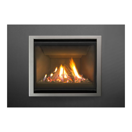
Product description The Escea AF700 gas fire is a room sealed gas appliance designed to be built into a masonry cavity or a false chimney cavity. The AF700 is provided with standoff rails installed to the outside of the chassis to attain a zero clearance rating. -
Page 7: A3 Product Dimensions
Product Dimensions All outside dimensions taken from the appliance are with the standoffs attached 693mm 387mm 711mm* 596mm 593mm* *Fascia Dimensions. END OF SECTION A By the end of this section, you should have: A framed false cavity A masonry cavity sized to suit the appliance... -
Page 8: Creating The Cavity
Masonry install with 585mm 685mm 385mm Standoff Rails Re- moved *Note: If cavity dimensions significantly exceed those specified, a register plate is available for pur- chase through your local escea retailer (New Zealand Only). False Cavity Installation Requirements... -
Page 9: B2 Floor Clearances
Masonry Installation Requirements The masonry install requires a spacer below the appliance to allow room for the fascia to sit flush with the ground. Floor Clearances If the appliance is mounted above a “hard floor” (including but not necessarily limited to: wood, wood veneers, ceramic tiles, concrete and stone) then it may be positioned with the bottom of the fascia coincident with the finished floor if desired. -
Page 10: B3 Corner Installations
The AF700 fireplace is zero clearance rated with the standoff rails installed on the ouside of the chas- sis. The standoff rails may only be removed when installing the fire into a masonry cavity. -
Page 11: B7 Mantle Clearance
fire is suitable. Escea in no way guarantees or takes responsibility that the above in- stallation suggestion will be suitable for all electrical or home entertainment appliances. -
Page 12: Installing The Flue
fire to operate incorrectly and possibly create an unsafe condition. • This flue system cannot be cut to length. Correct lengths must be selected for each installation. For a full list of available flue lengths, contact your Escea retailer. - Page 13 • The listed length of the flue pipe is not the installed length. 1 ½” (38mm) needs to be subtract- ed for each join to determine the installed length of each piece of flue pipe. E.g. 48” length has installed length of 45”. •...
-
Page 14: C3 Supporting The Direct Vent Flue System
• Adjustable lengths are available depending on stock levels. Contact escea for more information. The flue must maintain the following clearances to combustible materials; 25mm from all sides and bottom of the flue, and 50mm from the top of the flue: Supporting the Direct Vent flue system... -
Page 15: C5 Twist Locking Procedure
Installing Converter Box The AF700 only comes with a spigot plate suited for flexi flue, because of this, a converter box is required to convert a 300mm, 4” and 3” flexi flue length to Simpsons Duravent 4” x 6” direct vent flueing. - Page 16 Locate the 30cms long piece of fibreglass tape in the accessory pack provided with the AF700 fire. Remove the tape backing and adhere it to the Exhaust spigot of the Co-axial transition box spigot approximately 10mm off the face of the planer surface of the transition box.
- Page 17 Place the band clamp over the exhaust flexi flue. Position the band so that it aligns with the fibreglass tape underneath (approximately 15mm off the planar surface of the transition box). Tighten the band clamp. ONLY TIGHTEN ENOUGH TO JUST HOLD AND PREVENT THE FLEXI FLUE FROM COMING OFF THE SPIGOT IF PULLED ON.
-
Page 18: C7 Vertically Terminating Flue Restriction Diagram
Vertically Terminating Flue Restriction Diagram NOTE: If your flue configuration falls on or near a restriction zone boundary line in diagrams locat- ed in section C7 or C8, it may require the restriction setup from either side of the boundary line to achieve the correct flame aesthetic (refer to E11 for flame aesthetic), this may vary from installation to installation. -
Page 19: C8 Horizontally Terminating And Vertically Terminating With A Horizontal Offset Flue Restriction Diagram
C8 Horizontally Terminating and Vertically Terminating with a Horizontal Offset Flue Restriction Diagram NOTE: If your flue configuration falls on or near a restriction zone boundary line in diagrams located in section C7 or C8, it may require the restriction setup from either side of the boundary line to achieve the correct flame aesthetic (refer to E11 for flame aesthetic), this may vary from installation to installation. -
Page 20: C9 Flue Terminal Clearances
C9 Flue Terminal Clearances Horizontal Termination Clearances This diagram applies to all horizontal flue type installations on this appliance. - Page 21 Vertical Termination Clearances This diagram applies to all vertical flue type installations on this appliance 500mm minimum to nearest surface...
- Page 22 Minimum Clearances Ref. Item (mm) Natural draught assisted Below eaves, balconies and other projections: Gas appliances up to 50 MJ/h input Gas appliances over 50 MJ/h input From the ground, above a balcony or other surface (see note 6) From a return wall or external corner (see note 6) From a gas meter (M) (see 2.5.4.9 for vent terminal location of Regulator) 1000...
-
Page 23: C10 Connecting The Flexi Flue To The Masonry Terminal Kit
C10 Connecting the Flexi flue to the Masonry Terminal Kit (46DVA-CL34) NOTE: The chimney kit 46DVA-CL34 must only be installed into a non-combustible masonry or concrete chimney. Locate the 100mm (4”) exhaust flexi flue. Stretch the flexi flue to the desired length ensuring that the end part that fits onto the exhaust spigot is completely extended (stretched). -
Page 24: C11 Setting Up The Flue Spigot Plate
C11 Setting up the Flue Spigot Plate Connect the flexi flue to the spigot plate while the cavity is still empty using the hose clamps provided. END OF SECTION C By the end of this section, you should have: For a false cavity installation: a self supporting converter box with a 3” and 4” 300mm length of flexi flue attached to the flue spigot plate dangling flush with the top of the cavity opening. -
Page 25: Installing The Electricity And Gas To The Appliance
(Service section). D2 Removing the Glass The AF700 fireplace has two layers of glass; the inner glass seals the firebox and is called the prima- ry glass, the outer glass is called the secondary glass. Secondary Glass 1. -
Page 26: D3 Removing The Burner Tray
Primary Glass 3. Lift the extrusion cap upwards; located on the top of the primary glass. 4. Remove the two screws in each of the two side brackets. 5. Pull the top of the glass toward you slightly, lift the glass out of the bottom glass retainer and carefully set glass aside. -
Page 27: D4 Gas Pipe Sizing
AF700 Gas Consumption = 25MJ/hr D5 Gas Pipe Position The AF700 gas pipe entry point is located in the lower right corner; a sheet of silicone is used as a grommet (circled below). Get the gas pipe lined up with the silicone grommet so that when the chassis is pushed into the cavity in section E the fire will look like the diagram shown below. -
Page 28: Installing The Appliance
Installing The Appliance Installation Note: Ensure the wall has been correctly framed to the dimensions specified in section B1 before starting the appliance install. The wall must be lined after the fire has been fitted into the cavity With the appliance electrical cord plugged into an outlet, carefully place the appliance in front of the cavity base. -
Page 29: E3 Removing The Burner Tray
Make sure that all six of the fold up tabs (shaded in the diagram below) used for locating the flue spigot plate onto the chassis are poking through the flue spigot plate. Insert the 2 long self tapping screws into the location shown in the diagram above to secure the flue spigot plate to the chassis. -
Page 30: E4 Fixing The Appliance To The Base
Fixing the Appliance to the Base An appropriate fastening can be screwed down to the cavity base through the 2 circled holes in the diagram below. Top View of Chassis Base Network Cable If the appliance is to be wired to a home automation system or internet router/network being installed then provision must be made for the network cable to get to the electronics tray. -
Page 31: E6 Connecting The Gas Pipe To The Regulator
Note: The regulator that is supplied with the fire MUST NOT BE REMOVED. Removal of the regulator, or replacing it with one not intended for use with an Escea fire, will void the limited appliance warranty. The gas connection on the appliance regulator is a ½” female BSPP at the front right of the appliance;... -
Page 32: E9 Checking The Operating Pressure
Checking the Operating Pressure WARNING: The regulator that is supplied with the fire MUST NOT BE REMOVED. Removal of the regulator, or replacing it with one not intended for use with an Escea fire, will void the limited appliance warranty. -
Page 33: E10 Converting The Appliance Gas Type
Adjust the operating pressure by feeding a screw driver through the front face of the fireplace and turning the regulator adjustment screw. Tighten the operating test point screw and leak test both test points using a soapy water solution. Replace the test point hatch E10 Converting the Appliance Gas Type This appliance has been factory set to operate on Natural Gas only. -
Page 34: E11 Flame Picture
An abnormal flame pattern will likely be the result of incorrect settings (jet size, burner aeration collar, flue restriction), and if present you must check these are correct before proceeding. If an abnormal flame pattern is still present, please contact Escea. It is the responsibility of the installer to ensure a correct flame pattern. -
Page 35: E15 Log Fuelbed Installation
Refer to section D2 and reverse the steps. E15 Home automation Setup The AF700 fireplace has a simple interface for connection to a home automation system. Simply put this allows the fireplace to be woken up and started and then shut down. The “Close to wake” con- nection shown is essentially taking one of the 3.3 volt DC pins on the fireplace micro controller and... -
Page 36: E15 Home Automation Operation
μ From Automation system Connector and terminal block supplied by Escea Note: you will need to match the relay coil voltage with the volt- age from your automaton system. The Home Automation connection can be found to the right of the electronics tray (for access instructions see section E3). -
Page 37: Fitting The Fascia And Finishing Installation
A suitable distance away from the heater. Ideally 1.2m to 1.5m from the floor The radio frequency signal will go through some walls but for best results Escea suggest that the cradle position is between 1 and 5 metres away from the heater. -
Page 38: F3 Operating The Appliance For The First Time
Operating the Appliance for the First Time Remove the battery cover on the rear of the remote. Insert the new “AA” size batteries, paying atten- tion to the polarity. You should now see on the display of the remote the time showing “0:00”. To turn the fire on, press the “POWER”... -
Page 39: F4 Normal Operating Sounds And Smells
• Fan: Escea gas appliances use electric fans to push heated air further into the room. It is not un- usual for the fan to make a “whirring” sound when ON. This sound will increase or decrease in volume depending on the speed setting of your fan. -
Page 40: Freestanding Unit (Fs730) Installation
Freestanding Unit (FS730) Installation Product Dimensions All outside dimensions taken from the appliance are with the standoff rails attached 735mm 124mm 505mm 381mm 368mm 368mm 753mm G2 Hearth and Clearances A Hearth is not required, however it may be used for decorative purposes or for protection of sensitive flooring. -
Page 41: G3 Flue Installation
G3 Flue Installation The freestanding unit and flue system should be installed prior to the AF700 being installed. Rigid flue Place the freestanding unit in the desired location, complying with the clearances specified in the previous section. Duravent 4x6” Rigid Direct-vent... -
Page 42: G4 Af700 Fireplace Installation Into Fs730 Freestanding Unit
G4 AF700 Fireplace installation into FS730 Freestanding Unit Once the freestanding unit is in place, and the flue system installed, the AF700 fireplace installation can commence. Place the freestanding unit location, complying with the clearances specified in the previous section. -
Page 43: Installation Checklist
Installation Checklist Go through the following checklist to ensure you have installed the appliance correctly Correctly sized cavity to suit your fascia and flue configuration Correct clearances to combustibles and mantles around the fascia An electrical isolating switch to the appliance, accessible after finished installation Correctly sized gas supply with a pressure test point, ensuring adequate supply with all other gas appliances in the dwelling running A weather-tight installed Horizontal or Vertical Flue Terminal with clearance as... -
Page 44: Service Manual
Service Manual IMPORTANT: • This appliance must be serviced every 12 months. • Any service operation should be carried out only by a suitably qualified and trained person. • Gas and electricity supply MUST be isolated before any service operation is carried out on this appliance. -
Page 45: S2 Serial Number
The bimetallic snap disk mounted on the back chassis panel has tripped. The possible causes for this could include: • Fascia may be installed incorrectly resulting in restricted air flow. • The room air fan may be slowed or stalled. Remove firebox, check that Appliance Over the fan is plugged in, cleaned, and free turning. -
Page 46: S4 Cleaning The Fascia
NEVER RUB THE FASCIA. The outside of the fascia’s must only be cleaned with a clean damp cloth, dry off after cleaning. The high temp silver powder coating that is used on Escea fascia parts contains certain amounts of aluminium that when rubbed too hard will oxidise leaving a black smudge that cannot be removed. -
Page 47: S7 Removing The Electronic Tray
Removing Electronic Tray ISOLATE THE POWER TO THE FIRE BEFORE THIS PROCEDURE. All of the electronic components of the heater have been located on a removable tray. Remove the 18-way connector from the end of the tray, the network cable, if installed (both locations circled in diagram below) and the transformer connector located in the rear LH corner of the electronics tray. -
Page 48: S8 Replacing The Thermal Cut Out
Replacing the Thermal Cut Out Once the firebox base, electronic tray, and fan have been removed (As per previous sections), the Ther- mal Cut Out can be removed and replaced if required. Disconnect the electrical plug connecting the TCO bracket (shown right) to the fireplace wiring harness. -
Page 49: S9 Replacing A Wireless Control
If the wireless control becomes lost or damaged, a new one can be ordered from any Escea retail agent. When you have the new remote, the following procedure needs to be followed to “teach” the remote to only communicate with that fire. -
Page 50: S10 Annual Service Procedure
S10 Annual service procedure Isolate power and gas supply to fire. Remove front glass and clean inside of glass. Remove fuel bed and brush off any soot. Clean electrode and pilot hood of any carbon build up and ensure correct gaps between electrode and pilot hood Remove burners and blow compressed air through the burner ports. -
Page 51: S11 Wiring Diagram
S11 Wiring Diagram...
Need help?
Do you have a question about the AF700 and is the answer not in the manual?
Questions and answers