
Subscribe to Our Youtube Channel
Related Manuals for Grundig GCA-B3323V


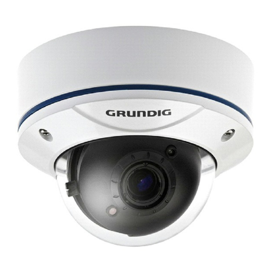
Summary of Contents for Grundig GCA-B3323V
- Page 1 Owner's Manual Cameras & Domes GCA-B3323V 1/3" CCD Col/B&W Fixed Dome Camera GCA-B3326V 1/3" CCD Col/B&W Fixed Dome Camera w/ IR LED GCA-B3323V.42.1.09.02.2012 © ASP AG...
-
Page 3: Table Of Contents
Content: 1. Available Versions 2. Important Safety Instructions 3. Package Contents 4. Installation 1. Part Names 2. Base Installation 3. Mounting Housings to Electrical Junction Boxes 4. Connections 5. 3-Axis Gimbal Adjustment 6. Zoom & Focus Adjustment 7. IR-LED On/Off Switch 8. -
Page 4: Available Versions
Continued use in such a condition may cause fire or electric shock. If this product fails to operate normally, contact the nearest service center. Never disassemble or modify this product in any way. (GRUNDIG is not liable for problems caused by unauthorised modifications or attempted repair.) To prevent fire or electric shock, do not expose the inside of this device to rain or moisture. -
Page 5: Package Contents
3. Package Contents These parts are included: - Torx Wrench: Length 90mm (1pc) - Dowel: Length 30mm, Thickness 6mm (4pcs) - Assembly Screws: FH M4x14 (4pcs) - Mounting Screws: ST4x38 (4pcs) These screws are used to mount both surface mount plate or flush mount base to a sturdy surface. -
Page 6: Part Names
When installing the unit, fasten it securely and firmly. A falling unit may cause personal injury. If you want to relocate the already installed product, be sure to turn the power off and then move or reinstall it. 4.1. Part Names 1. -
Page 7: Base Installation
4.2. Base Installation 1. Remove the dome cover by loosening the 3 screws. Use the Torx wrench supplied. 2. Surface Mount : Using the four ST4x38 screws, mount the surface plate to a sturdy surface. Using the four M4x14 screws, affix the flush mount base to a surface plate. (For flush mount application, disregard section 2.) 3. -
Page 8: Mounting Housings To Electrical Junction Boxes
4.3. Mounting Housings to Electrical Junction Boxes This unit can be either flush mounted or surface mounted with Electrical Junction Boxes using the pre-drilled mounting holes. The dome housing accommodates various electrical junction boxes, making the installation easy and less time consuming. NOTE: The screws required for electrical junction boxes are not supplied with the Dome. -
Page 9: Connections
4.4. Connections - Power connection: Requires a DC 12V or AC 24V input depending on the camera model. - All camera models are supplied with a service monitor output on the camera module. A control cable is included in the package. Note: To set up the OSD menu externally, a control cable is required. -
Page 10: Zoom & Focus Adjustment
4.6. Zoom & Focus Adjustment If you need to make viewing angle/focus adjustments, loosen the lever bolts and make the necessary adjustments as shown. - Field of View: Telephoto (T) to Wide (W) - Focus: Near (N) to Infinity (oo) After the adjustments are completed, tighten the Zoom/Focus levers. -
Page 11: Fan & Heater (Optional)
4.8. Fan & Heater (optional) For Fan & Heater operation, AC24V power is required. Cameras that operate with 12V cannot support the Fan & Heater function. 5. OSD Control Keys - SET key: Accesses the menu mode or confirms the setting. - UP (/\) / DOWN (\/): Chooses the desired menu. -
Page 12: Osd Menu
6. OSD Menu 1. Press the SET key and hold it for a while to access the menu mode. 2. Select the desired feature by using the UP/DOWN keys (/\ \/) on the control. 3. If there is a setting for this feature on the the right side of the screen, use the LEFT/RIGHT keys to switch between the settings and confirm your choice by pressing the SET key. -
Page 13: Lens
CAMERA ID: Here you can assign a unique name or title to the camera. MOTION DET: This function is used to detect moving objects in the monitoring area. PRIVACY: You can mask specific areas in the monitoring area here. SYNC: This function refers to the Internal Syncronisation. -
Page 14: Shutter/ Agc
6.2. SHUTTER/ AGC This function is used to control the light exposure. You can either select AUTO for the auto iris lens (here you can set the shutter value and the brightness level depending on the lighting conditions) or you can choose MANUAL for the manual iris lens (here you can set up the electronic shutter speed and the AGC value manually). -
Page 15: White Bal (White Balance)
MANUAL: Here you can set the SHUTTER value and the AGC value. - MODE [SHUTTER+AGC] : The mode is fixed to SHUTTER+AGC. - SHUTTER [NTSC: 1/60, 1/100, 1/250, 1/500, 1/1000, 1/2000, 1/4000, 1/1000; PAL: 1/50, 1/120, 1/250 ~ 1/10000] : Choose the desired value. - Page 16 PUSH: Adjusts the white balance regardless of the conditions. USER1: This mode is the fixed outdoor gain mode and is fitted for outdoor lighting conditions. - B-GAIN: Adjusts the White Balance for the colour Blue. - R-GAIN: Adjusts the White Balance for the colour Red.
-
Page 17: Pict Adjust (Picture Adjustment)
MANUAL: This function allows the white balance to be adjusted manually. An increased level produces a strong blue tone on the screen and a decreased level produces a strong red tone on the screen. PUSH LOCK: This mode is set to the current white balance conditions and keeps its value. Select this mode and then press the SET key. -
Page 18: Nr (Noise Reduction)
6.5. NR (Noise Reduction) NR MODE [OFF, Y, C, Y/C] : This function is used to improve the picture quality by filtering the noise which is generated under low bright light conditions. You can set up Y (luminance), C (chroma) and Y/C mode as well as adjust the the filtering level/s for each mode. -
Page 19: Camera Id
6.8. CAMERA ID This menu is used to assign a unique name to a camera. You can enter up to 52 alphanumeric or special characters for the CAMERA ID. Select POS and press the SET key to be able to move the display position of the CAMERA ID. -
Page 20: Motion Det (Motion Detection)
B/W [BURST, IR OPTIMIZER, MODE, LEVEL] : If set to B/W, the camera will be fixed to B/W mode regardless of the ambient conditions. - BURST: Set this option to ON to output a burst signal in B/W mode. - IR OPTIMIZER: Set the IR OPTIMIZER to ON to control the screen overexposure caused by the camera's bright LED light in dark ambient conditions. -
Page 21: Privacy
DETECT SENSE [000~127] : Sets the motion detection sensitivity. BLOCK DISP [OFF, ON, ENABLE] : Controls the ON/OFF status of the motion detection block display. - ON, OFF: Turns the block display on/off. - ENABLE: If the BLOCK DISPLAY is set to ON, you can choose in this setting with the SET key areas where the motion detection (in block format) should not be displayed. -
Page 22: Sync
AREA SEL [1/8 ~ 8/8] : Here you can select the setting for each of the 8 mask areas. If MONITOR AREA in the MOTION DET menu has been set to ON, four areas will be selected. - TOP: Sets the top side of the selected mask area. - BOTTOM: Sets the bottom side of the selected mask area. - Page 23 Specifications GCA-B3323V Image Sensor 1/3" CCD Sony 960H Ex-view HAD II Scanning System PAL, 50Hz, 625L (V), 2:1 Inter Line Transfer Pixels - Effective 976(H) x 582(V) Resolution 700 (H) lines colour, 750 (H) lines b&w Col/B&W Auto, IR-cut filter removable (ICR) Sensitivity Colour 0.1 Lux (50IRE) @ F1.2...
- Page 24 Dimensions English...
-
Page 25: Ec Declaration Of Conformity
EC Declaration of Conformity GCA-B3323V 1/3" CCD Col/B&W Fixed Dome Camera GCA-B3326V 1/3" CCD Col/B&W Fixed Dome Camera w/ IR LED It is hereby certified that the products meet the standards in the following relevant provisions: EC EMC Directive 2004/108/EC...
Need help?
Do you have a question about the GCA-B3323V and is the answer not in the manual?
Questions and answers