Table of Contents
Advertisement
Advertisement
Table of Contents

Subscribe to Our Youtube Channel
Related Manuals for Provision ISR Mini Ultra-Z Z-10AHD-1 (IR) PTZ


Summary of Contents for Provision ISR Mini Ultra-Z Z-10AHD-1 (IR) PTZ
- Page 1 [Date] Tal Hanoch PROVISION-ISR...
-
Page 2: Z-10Ahd-1 (Ir) Ptz
Package Contents: Item Qty. Z-10AHD-1 (IR) PTZ DC12V/3A power supply Wall Screws... -
Page 3: Table Of Contents
Table of Contents: 1 General Instructions: ..............3 1.1 Safety Instructions: ................3 1.2 Warnings: ..................3 2 Features: ..................4 2.1 Product Picture: ................4 2.2 Product Features ................4 2.3 Specifications: .................. 5 3 Installation Site Preparations: ............. 6 3.1 Tool List: ................... -
Page 4: General Instructions
1 General Instructions: 1.1 Safety Instructions: Make sure to read the user manual before using the camera. Always follow national and local safety codes during the installation. Only qualified and experienced person can carry the installation and maintenance for this camera. -
Page 5: Features
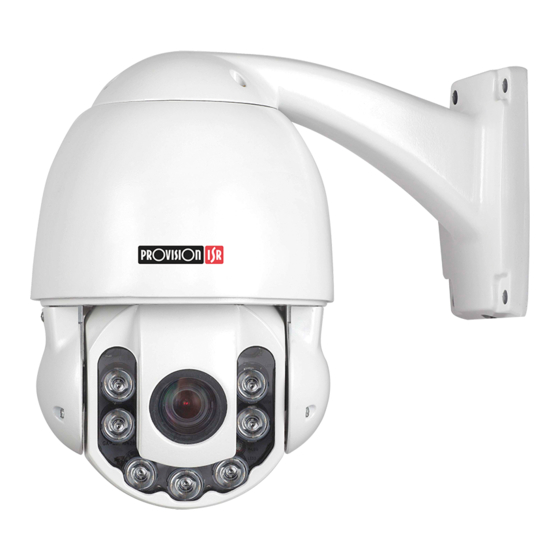
2 Features: 2.1 Product Picture: 2.2 Product Features Adaptive PELCO-P/D protocol. Adjustable IR illumination. Memory recall. Real-Time-Control: call any functions at any time. Support 128 preset positions. English OSD menu. Proportional zoom. Auto flip function. -
Page 6: Specifications
2.3 Specifications: Input:AC100~240V 50/60Hz Power Supply Output:DC12V±5%,3A Max. Power IR off:~7.2W Consumption IR on:~19.8W Sync system Internal Sync Language English Signal Output AHD/CVBS + PAL/NTSC Pan Speed 0.08°~240°/S (Max. Preset Speed) Tilt Speed 0.08°~240°/S (Max. Preset Speed) Pan Range 0°~360°(Continuous) Tilt Range 0°~90°(180°... -
Page 7: Installation Site Preparations
3 Installation Site Preparations: 3.1 Tool List: (1) Screws* (2) Monkey wrench (3) Philips screwdriver (4) Straight Screwdriver (5) Wire stripper (6) Socket head wrench (7) Electric drill (8) Hammer (9) BNC connector (10) BNC Clamp *Included in the kit 3.2 Installation Preparation: (1) Check the space and toughness of the site and make sure that the environmental conditions meet the installation requirements for this product. -
Page 8: Output Mode Setting
Auto detected 2400、 600-1800 4800、9600、 19200BPS (3) When the DIP Switch 9th and 10th are ON, the PTZ can automatically detected the baud rate 2400, 4800,9600,19200 (4) Hardware Address Setup*: Please refer to Appendix I. *Please note that the address setting can also be configured via the software using the camera OSD (Page 11). -
Page 9: Enter The Osd Menu
PROTOCOL: PELCO P D BAUD RATE: 2400BPS CAMERA ID: 001 CAMERA S/N: 0000000001 MODEL: ----------------- VERSION: V1.02 FAN SPEED: 6000RPM STARTING… …. When starting, the PTZ will display the following information: Level self-check: Success Vertical self-check: Success Success Once done, the above information will disappear and the user will gain control over the camera. - Page 10 SYSTEM LENS PAN/TILT AUTO RUNNING IR SET EXIT...
-
Page 11: System Menu
4.3 SYSTEM Menu: <Main Menu> <SYSTEM> SITE INFO DISPLAY SETUP BOOTUP SCREEN SET DEFAULT SYSTEM REBOOT BACK EXIT System info includes following settings. < SITE INFO>: In this menu the user can setup the dome’s name, View the Hardware address, change the camera software address and choose the leading command (Hardware or Software). - Page 12 4.3.1 SITE INFO DOME ID OPT: HARD SOFTWARE ID: HARDWARE ID: BROADCAST ID: BACK EXIT <Main Menu> <SYSTEM> <SITE INFO > <DOME ID OPT>: Setting the address method that controls the dome, user can choose from SOFT (Software – As defined below in the OSD menu) and HARD (Hardware –...
- Page 13 <BACK>: return to upper menu. <EXIT>: exit the menu 4.3.2 DISPLAY SET UP < Main Menu><SYSTEM><DISPLAY SETUP> PRESET TITLE: PATTERN NAME: OFF ORIENATATION: OFF TEMPRETURE: BACK EXIT <PRESET TITLE>:Choose to display preset position or not. <PATTERN NAME>:Choose to display pattern name or not ...
-
Page 14: Lens
<Main Menu><SYSTEM><DISPLAY BOOT-UP INFO> Enter into Boot-up info displays to check current setup, call preset 1 to return to upper menu 4.3.5 SET DEFAULT <Main Menu><SYSTEM><SET DEFAULT> Select <SET DEFAULT> to restore factory default setting. Please note: there is no confirmation prompt! Once entering the camera will immediately restore itself. - Page 15 <BOTH>: Joystick movement triggers both auto focus and auto iris <FOCUS>:Joystick movement triggers auto focus only <IRIS>: Joystick movement triggers auto iris only. <NONE>: Joystick movement triggers none of the functions.。 <AF RESUME TIME>: This item sets the time to restore auto focus after focus is manually changed.
-
Page 16: Advanced Camera Menu
4.5 Advanced Camera Menu: For advanced Menu, Call preset #69. PLEASE NOTE: Scrolling and changing values in the advanced menu is done with different controls: The controller joystick has effect. Scrolling up and down is done by pressing IRIS+/IRIS- Changing Values of the selected feature is done by pressing ZOOM+/ZOOM- IMPORTANT!!! Changing any values the advanced menu might result in the camera malfunctioning... - Page 17 <LANG>: Language of the menu (Only English Available) <OSD-DISP >: Do Not Change <ADDR-DISP>: Do Not Change <D&N>: Do Not Change <D&N-LV>: Do Not Change <N&D-LV>: Do Not Change <MIRROR>: Turning Mirror effect ON/OFF ...
- Page 18 <WB>: White Balance is normally compensated for by the automatic white balance gain control. In some lighting conditions, user may want to manually adjust the red and blue settings for optimal viewing. There are 6 options: [AUTO]: Auto White Balance (default setting). ...
-
Page 19: Pan/Tilt
4.6 PAN/TILT <Main Menu><PAN/TILT> AUTO STOP TIME: SPEED AMPLIFY: RATIO PAN/TILT: SET NORTH BACK EXIT <AUTO STOP TIME>: For some particular protocols, the dome will not stop moving even there is no operation by the controller. This menu sets the time duration before stopping after which the dome receives last control command. -
Page 20: Auto Running
<SET NORTH>: User can set orientation by using joystick to position north. When select <SET NORTH>, following menu will pop-up. CALL PRESET 1 TO RETURN CONFIRM..Adjust the lens to desired position and call preset 1 to confirm and return. 4.7 AUTO RUNNING <Main Menu><AUTO RUNNING>... - Page 21 PRESET NUMBER: SET CURRNET REMOVE CURRENT BACK EXIT In this function, the values of the pan/tilt positions will be stored in the desired memory slot so that you will be able to call it when in need. 128 presets can be saved. It could also setup by shortcuts of control system. ...
- Page 22 TOUR NUMBER: 001 DWELL: 003 EDIT BACK EXIT The dome camera will run repeatedly as the given sequence of presets at certain dwell time by one command. Max. 4 tours available (27preset/tour). <TOUR NUMBER>: Set current tour number from 001~004. ...
- Page 23 There are three group numbers, the left side is preset number, the right side is dwell time; tour from left to right, up to down in the order to run preset; when the preset number is set to < 000>, the current preset is skipped; ...
- Page 24 even without calling preset 1. <RUN>: Run current pattern repeatedly until other command received. 4.7.4 360° SCAN <Main Menu> <AUTO RUNNING> <360° scan> 360° SCAN DWELL: 0S PAN SPEED: HIGH BACK EXIT <360° SCAN DWELL>: [0S]: 360 continuous scan [5S]: 90 intermittent scan, then dwell on 5s, the dome will continuously run at the given route repeatedly until receiving new command.
- Page 25 <Main Menu> <AUTO RUNNING> <ZONE> LEFT LIMIT RIGHT LIMIT PAN SPEED:LOW REMOVE CURRENT BACK EXIT <LEFT LIMIT>: Set the right edge of region <A> CALL PRESET 1 TO BACK CONFIRM..Move the camera left limit position to confirm and return. The position of the left limit position will now be marked on the menu screen.
- Page 26 Auto:Do as the camera’s proportional P/T speed. <REMOVE CURRENT>: Delete current zone <RUN>: Start current zone scan repeatedly before receiving new command. Note: PTZ default tour scan direction is clockwise starting from the left limit. If the user finds out the route is wrong, he should call preset 82 preset again and PTZ will scan in the reverse direction.
-
Page 27: Ir Set
4.8 IR SET <Main Menu> <IR SET> IR MODE SET: AUTO IR ZOOM SET 2: 006 PRESENT LUX: 010 IR START SET: 006 IR CLOSE SET: 012 BACK EXIT <IR MODE >: AUTO/OPEN/CLOSE <AUTO>: Default. When the detected signal value from the IR sensitive below the value of IR Start, the IR dome automatically open the IR lights. -
Page 28: Appendix I: Dip Switch Setting
APPENDIX I: DIP SWITCH SETTING DIP Switch consists of 8 numbers from 1-8, use 8421 binary cod, max 255 address. When the switch is in the “ON” position, the number from 1-8 corresponding to 1, 2, 4, 8, 32, 64, 128. For example, if you set 1, 3, 5, 7 switch to the “ON”... - Page 29 1 1 0 0 0 1 0 0 0 0 1 0 0 1 0 0 1 0 1 0 0 1 0 0 0 1 1 0 0 1 0 0 1 1 1 0 0 1 0 0 0 0 0 1 0 1 0 0 1 0 0 1 0 1 0 0 0 1 0 1 0 1 0 0...
- Page 30 1 0 0 1 1 0 1 0 0 1 0 1 1 0 1 0 0 0 1 1 1 0 1 0 0 0 1 1 1 0 1 0 1 0 1 1 1 0 1 0 0 1 1 1 1 0 1 0 1 1 1 1 1 0 1 0 0 0 0 0 0 1 1 0...
- Page 31 1 1 1 1 0 0 0 1 0 0 0 0 1 0 0 1 1 0 0 0 1 0 0 1 0 1 0 0 1 0 0 1 1 1 0 0 1 0 0 1 0 0 1 0 1 0 0 1 1 0 1 0 1 0 0 1 0 1 1 0 1 0 0 1...
- Page 32 1 0 1 0 0 0 1 1 0 1 1 0 0 0 1 1 1 1 1 0 0 0 1 1 0 0 0 1 0 0 1 1 1 0 0 1 0 0 1 1 0 1 0 1 0 0 1 1 1 1 0 1 0 0 1 1 0 0 1 1 0 0 1 1...
-
Page 33: Appendix Ii Shortcuts Key Chart
APPENDIX II Shortcuts Key Chart: *Relevant for all models produced in 2016 and later. For older production please contact Provision-ISR’s technical support Shortcut Key Function (Set Preset) Set #84preset Proportional P/T OFF Set #85preset Set Output: AHD PAL Set #86preset Set Output: AHD NTSC Set #87preset Set Output: CVBS PAL... - Page 34 Set #106 preset Record Pattern scan 4 Set #107 preset Set cruise 1 Set #108 preset Set cruise 2 Set #109 preset Set cruise 3 Set #110 preset Set cruise 4 Set #111 preset Set color-to-black function Set #112 preset Set 360°scan, the preset-dwell: 0S Set #113preset Set 360°scan, the preset-dwell: 5S...
-
Page 35: Appendix Iii Trouble Shooting
APPENDIX III Trouble Shooting Troubles Reason Solution 1. The power supply is not 1. Correct the connection. No action when power on connected correctly. 2. Check the power supply LED 2. The fuse is broken. power indicator. 3. Replace the fuse. 1.
Need help?
Do you have a question about the Mini Ultra-Z Z-10AHD-1 (IR) PTZ and is the answer not in the manual?
Questions and answers