Table of Contents
Advertisement
Quick Links
Advertisement
Table of Contents

Related Manuals for Gage Bilt GB745


Summary of Contents for Gage Bilt GB745
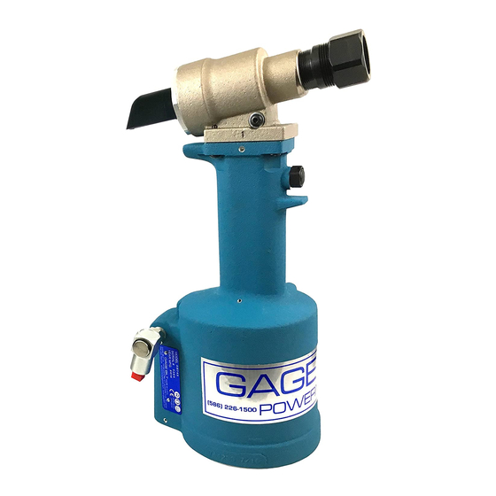
- Page 1 GB745 INSTALLATION TOOL GAGE BILT TOOLS ARE AVAILABLE WORLDWIDE E-MAIL US FOR A DISTRIBUTOR NEAR YOU. GAGE BILT Inc. GAGE BILT 44766 Centre Court (586) 226-1500 Clinton Twp. MI 48038 (586) 226-1505 Fax MADE IN U.S.A. e-mail: solutions@gagebilt.com / www.gagebilt.com...
-
Page 2: Table Of Contents
TABLE OF CONTENTS Description Page Warnings ..................................... 3 Principle of Operation ................................4 How to use the GB745 ................................5 Description, Operation and Maintenance ..........................6 Filling and Bleeding .................................. 7 Troubleshooting and Overhaul ..............................8 Disassembly and Parts Lists..............................9-10 DEXRON®... -
Page 3: Warnings
SAFETY WARNINGS OPERATING HAZARDS: TERMS AND SYMBOLS 1. Use of tool can expose the operator’s hands to hazards, including crushing, impacts, cuts, abrasions and heat. Wear suitable gloves to protect hands. - Product complies with requirements 2. Operators and maintenance personnel shall be physically able to handle the bulk, weight and power of the tool. -
Page 4: Principle Of Operation
PRINCIPLE OF OPERATION When the air actuator assy is depressed, the pressurized air inside the tool is released allowing spring pressure to move the valve spool assy, causing the air to be redirected. The air is directed to the top side of the air piston assy, moving it in a downward direction. -
Page 5: How To Use The Gb745
HOW TO USE THE GB745 WARNING: Operator MUST read and understand all warnings and cautions. WARNING: It is required that eye protection and hearing protection be worn during operation. WARNING: Do not pull rivet in the air. Personal injury from fastener ejecting may occur. -
Page 6: Description, Operation And Maintenance
.620” (15.75 mm) rivet setting stroke and a rated pull load of 6,300 lbs (28.02 kN) with 90 psi (6.2 bar) air pressure at the air inlet. The GB745 riveter operates on a wide range of air pressure, with 90 to 100 psi (6.2-6.9 bar) providing the maximum efficiency. At 90 psi. -
Page 7: Filling And Bleeding
FILLING AND BLEEDING INSTRUCTIONS NOTE: Air bleeder assy (704153) is required. WARNING: Do not cycle tool without air bleeder assy (704153), or the button head cap screw (402482) and stat-o-seal (S572), installed in the head cylinder (745366). Severe personal injury may result. CAUTION: Before filling handle assy (744129), the air piston assy (744121) should be all the way down. -
Page 8: Troubleshooting And Overhaul
WARNING: Tool must be maintained in a safe working condition at all times and examined on a regular daily basis for damage or wear. Any repair should be done by qualified personnel trained on Gage Bilt procedures. WARNING: When operating, repairing or overhauling tool, wear approved eye protection. Do not look in Front of tool or rear of tool when installing fastener. -
Page 9: Disassembly And Parts Lists
HEAD Remove nose assembly from tool before attempting disassembly of head cylinder (745366). Remove end cap (745816). Push against threaded end of piston (745310) to slide it out of head cylinder (745366). Be careful not to damage threads or cause burrs on polished piston rod surface. WARNING: Dispose of Hydraulic Oil in accordance with applicable regulations. -
Page 10: Air Valve
HANDLE To inspect air cylinder bore, remove base cover (744124). Any further disassembly will require removal of the head cylinder (745366) first. For complete disassembly, start by removing base cover (744124). Next, holding tool upright, remove four button-head cap screws (402479). Lift head cylinder (745366) from handle assy (744129) and set aside o'ring (S832) and gasket (745124). -
Page 11: Dexron® Iii Oil Safety Data
DEXRON® III OIL SAFETY DATA FIRST AID MEASURES Eye: No specific first aid measures are required. As a precaution, remove contact lenses, if worn, and flush eyes with water. Skin: No specific first aid measures are required. As a precaution, remove clothing and shoes if contaminated. To remove the material from skin, use soap and water. -
Page 12: Nose Assembly Selection Chart
OF A VDEL UK LIM ITED. CHERRYM A X® A ND M B C® A RE REGISTERED TRA DEM A RKS OF CHERRY A EROSP A CE FA STENERS. GAGE BILT CERTIFIES THE GB745 WILL INSTALL THE ABOVE FASTENERS *ALL OFFSET 204 SERIES NOSES REQUIRE 353204 ADAPTER, & ALL OFFSET 205 SERIES NOSES REQUIRE 353205 ADAPTER. -
Page 13: Declaration Of Conformity
GAGE BILT DECLARATION OF CONFORMITY MANUFACTURER: Gage Bilt Inc. 44766 Centre Ct. Clinton Twp. Michigan (586-226-1500) WE DECLARE THAT THE EQUIPMENT SPECIFIED HEREIN CONFORMS TO THE FOLLOWING DIRECTIVES AND STANDARDS Machinery Directive 2006/42/EC EN12100-1 & EN12100-2 EN792-1:2000+A1 EU REPRESENTATIVE Edgar Hausmann GmbH Förster-Busch-Str. 10 D-34346 Hann. Münden Germany EQUIPMENT DESCRIPTION: GB745 FASTENER INSTALLATION TOOL This product specified above conforms to the above dIrectives and standards.
Need help?
Do you have a question about the GB745 and is the answer not in the manual?
Questions and answers