Table of Contents
Advertisement
Quick Links
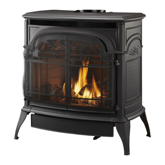
SDDVT Series Stardance
Installation and Operating Instructions
Models: SDDVTCBSB, SDDVTBSSB, SDDVTBDSB, SDDVTBMSB,
SDVTSCCB, SDVTSCBS, SDVTSCBD, SDVTSCBM
WARNING:
FIRE OR EXPLOSION HAZARD
Failure to follow safety warnings exactly
could result in serious injury, death or
property damage.
•
Do not store or use gasoline or other
flammable vapors and liquids in the
vicinity of this or any other appliance.
•
WHAT TO DO IF YOU SMELL GAS
– Do not try to light any appliance.
– Do not touch any electrical switch; do
not use any phone in your building.
– Leave the building immediately.
– Immediately call your gas supplier from
a neighbor's phone. Follow the gas
supplier's instructions.
– If you cannot reach your gas supplier,
call the fire department.
•
Installation and service must be performed
by a qualified installer, service agency or
the gas supplier.
WARNING: Improper installation, adjustment,
alteration, service or maintenance can cause
injury or property damage. Refer to this manual.
For assistance or additional information consult
a qualified installer, service agency or the
gas supplier.
This appliance may be installed in an aftermarket,*
permanently located, manufactured home (USA
only) or mobile home, where not prohibited by
local codes.
This appliance is for use only with the type of gas
indicated on the rating plate. This appliance is
not convertible for use with other gases, unless
a certified kit is used.
* Aftermarket: Completion of sale, not for purpose of resale, from
the manufacturer.
Direct Vent Gas Heater
®
DANGER
A barrier designed to reduce the risk of burns from
the hot viewing glass is provided with this
appliance and shall be installed.
INSTALLER: Leave this manual with the appliance.
DANGER
CONSUMER: Retain this manual for
future reference.
CERTIFIED
S
B
AFETY
ARRIER
12734
Stardance Dv
cover
8/07
HOT GLASS WILL
CAUSE BURNS.
DO NOT TOUCH GLASS
UNTIL COOLED.
NEVER ALLOW CHILDREN
TO TOUCH GLASS.
20306760 0416 Rev. 3
Un panneau vitré chaud peut
causer des brûlures.
Advertisement
Table of Contents
Troubleshooting

Related Manuals for Vermont Castings SDDVTBSSB


Summary of Contents for Vermont Castings SDDVTBSSB
- Page 1 SDDVT Series Stardance Direct Vent Gas Heater ® Installation and Operating Instructions Models: SDDVTCBSB, SDDVTBSSB, SDDVTBDSB, SDDVTBMSB, SDVTSCCB, SDVTSCBS, SDVTSCBD, SDVTSCBM CERTIFIED WARNING: AFETY ARRIER FIRE OR EXPLOSION HAZARD Failure to follow safety warnings exactly could result in serious injury, death or property damage.
-
Page 2: Table Of Contents
CONTENTS PLEASE READ THE INSTALLATION & OPERATING INSTRUCTIONS BEFORE USING APPLIANCE. Thank you and congratulations on your purchase of a Vermont Castings stove. IMPORTANT: Read all instructions and warnings carefully before starting installation. Failure to follow these instructions may result in a possible fire hazard and will void the warranty. -
Page 3: Important Safety Information
IMPORTANT SAFETY INFORMATION The Stardance Direct Vent Room heater, Model Nos. WARNING: Operation of this heater when not connected to a SDDVTCBSB, SDDVTBSSB, SDDVTBDSB, SDDVTBMSB, properly installed and maintained venting system can result SDVTSCCB, SDVTSCBS, SDVTSCBD, SDVTSCBM, is a vented in carbon monoxide (CO) poisoning and possible death. -
Page 4: Massachusetts Residents Only
Stardance Direct Vent Gas Heater ® IMPORTANT SAFETY INFORMATION REQUIREMENTS FOR THE Inspection COMMONWEALTH OF MASSACHUSETTS The state or local gas inspector of the side wall horizontally vented gas fueled equipment shall not approve the installa- All gas fitting and installation of this heater shall only be tion unless, upon inspection, the inspector observes carbon done by a licensed gas fitter or licensed plumber. -
Page 5: Pre-Installation
Stardance Direct Vent Gas Heater ® PRE-INSTALLATION STARDANCE DIRECT VENT STOVE DIMENSIONS Weight: Fully assembled; 202 lbs. See Page 7 for Flue Collar Centerline Dimensions. 7" Outer Dia. (178 mm) 12-5/8” (321 mm) 2-7/8” (73 mm) Flue Collar L C 26-3/4"... -
Page 6: Installation Requirements
Stardance Direct Vent Gas Heater ® PRE-INSTALLATION INSTALLATION REQUIREMENTS The installation must conform with local codes or, in the Direct Vent System Only absence of local codes, with the National Fuel Gas Code, ANSI Z223.1/NFPA 54 – latest edition. (EXCEPTION: Do not derate this appliance for altitude. -
Page 7: Parallel Installation
Stardance Direct Vent Gas Heater ® PRE-INSTALLATION Wall Centerline from Floor PARALLEL INSTALLATION Minimum Clearance and Flue Centerline Direct Vent Only Effective Minimum Wall Thimble 56” (1480 mm) (HHT Pipe) Stove Clearances: A: 4” (102 mm) Centerline 52” (1378 mm) (DuraVent Pipe) B: 4”... -
Page 8: Gas Specifications
Air Shutter Setting 1/2" open 1/2” open The installation of your Vermont Castings stove must conform with local codes, or in the absence of local codes, with the National Fuel Gas Code ANSI Z223.1/ NFPA 54 – latest edition, or CSA B149.1 Installation May use up to code. -
Page 9: Vertical Termination
Stardance Direct Vent Gas Heater ® PRE-INSTALLATION RESTRICTOR PLATE ADJUSTMENT VERTICAL TERMINATION FOR EXTENDED PIPE RUNS A vertical vent system must terminate no less than 8’ (2.44 m) and no more than 40’ (12 m) above the appliance flue The Stardance stove is shipped with a restrictor plate in collar. -
Page 10: Vent Termination Clearances
Stardance Direct Vent Gas Heater ® PRE-INSTALLATION VENT TERMINATION CLEARANCES Your stove is approved to be vented either through the side wall, or vertical through the roof. When planning the installation, consider the location of the vent terminal and clearances. Some of the most common •... -
Page 11: General Venting Information - Termination Location
Stardance Direct Vent Gas Heater ® PRE-INSTALLATION GENERAL VENTING INFORMATION – TERMINATION LOCATION INSIDE CORNER DETAIL Fixed Closed Fixed Operable Closed CFM145a AREA WHERE TERMINAL IS NOT PERMITTED VENT TERMINATION AIR SUPPLY INLET CANADIAN INSTALLATIONS CFM145a US INSTALLATIONS DV Termin Location 5/01/01 Rev. -
Page 12: Termination Clearances
Stardance Direct Vent Gas Heater ® PRE-INSTALLATION Termination Clearances Termination clearances for buildings with combustible and noncombustible exteriors. Inside Corner Alcove Applications* Outside Corner Combustible 6" (152 mm) Combustible 6" (152 mm) Noncombustible 2" (51 mm) Noncombustible 2" (51 mm) Balcony - Balcony - with no side wall... -
Page 13: Assembly And Installation
Stardance Direct Vent Gas Heater ® ASSEMBLY AND INSTALLATION DuraVent Components VENTING REQUIREMENTS AND OPTIONS Approved Vent System Components Minimum Horizontal Vent Kit 2792 The Stardance heater must be vented to the outdoors Starter Pipe Assembly (incl. inner & 2768* through an adjacent exterior wall or through the roof. -
Page 14: Assembling The Stove
Stardance Direct Vent Gas Heater ® ASSEMBLY AND INSTALLATION ASSEMBLING THE STOVE Tools Required • Phillips screwdriver (stub) • Utility knife • Metal drill bit: size 28 (.140"/3.5mm) • Flat-blade screwdriver • Power drill • Reciprocating saw • 9/16" wrench Parts Bag Contents: •... -
Page 15: Install The Optional Fan - Sddvt Models (Millivolt Only)
Stardance Direct Vent Gas Heater ® ASSEMBLY AND INSTALLATION WARNING This appliance is equipped with a three-prong (grounded) Rear Skirt plug for your protection against shock hazard and should be plugged directly into a properly grounded three-prong Sheet Metal receptacle. Do not cut or remove the grounding prong Screws from this plug. -
Page 16: Venting System Assembly
CAUTION raVent components. No other venting system compo- nents may be used. All Vermont Castings Direct Vent Stoves have been tested and approved to ANSI/CSA Standards and will • Horizontal runs must be supported every 3 feet (914 operate safely when installed in accordance with this mm) using wall straps. -
Page 17: Install The Vent Adapter Pipe
Stardance Direct Vent Gas Heater ® ASSEMBLY AND INSTALLATION WARNING Refer to pages 8 and 9 of this manual for the minimum and maximum venting requirements of your stove and for approved horizontal vent termination locations prior to installation. Failure to do so may cause fire hazard. WARNING Any horizontal run must have a 1/4”... -
Page 18: Assemble Slip Sections
Stardance Direct Vent Gas Heater ® ASSEMBLY AND INSTALLATION ASSEMBLE SLIP SECTIONS The outer flue of the slip section should slide over the outer flue of the pipe section and into (inner flue) the last pipe section (see Figure 23). Slide together to the desired length, making sure that a 11⁄2"... -
Page 19: Disassemble Vent Sections
Stardance Direct Vent Gas Heater ® ASSEMBLY AND INSTALLATION HORIZONTAL TERMINATION CAP WARNING Risk of Fire! The telescoping flue section of the termina- tion cap MUST be used when connecting vent. • 1 ⁄ ” (38 mm) minimum overlap of vent and telescop- ing flue section is required. -
Page 20: Divert Roof Run-Off
Stardance Direct Vent Gas Heater ® ASSEMBLY AND INSTALLATION DIVERT ROOF RUN-OFF Vent Opening for Combustible Walls HHT recommends, where excessive water run-off is 9" possible, use of one of the two options shown in Figure (244 mm) 29 to prevent water running off the roof and onto/into the horizontal termination cap. -
Page 21: Vent Termination Below Grade
Stardance Direct Vent Gas Heater ® ASSEMBLY AND INSTALLATION 6. Use appropriate length of pipe sections – telescopic VENT TERMINATION BELOW GRADE or fixed – and install. The sections which go through Install Snorkel Kit #SLP-SNORK when it is not possible to the wall are packaged with the starter kit, and can be meet the required vent termination clearances of 12"... -
Page 22: Vertical Through-The-Roof Application/Installation
Stardance Direct Vent Gas Heater ® ASSEMBLY AND INSTALLATION • The maximum angular variation allowed in the system Wall Screws is 270°. Figure 39 and Anchors Waterproof Seal • Around Pipe For the minimum height of the vent above the highest Snorkel Termination Firestop... - Page 23 Stardance Direct Vent Gas Heater ® ASSEMBLY AND INSTALLATION Horizontal overhang Horizontal overhang 20 in. Vertical Termination 24 in. min. (508 mm) (610 mm) Vertical 20 in. Lowest wall 24 in. min. (508 mm) Discharge (610 mm) Vertical Opening Lowest wall Termination Discharge...
- Page 24 Stardance Direct Vent Gas Heater ® ASSEMBLY AND INSTALLATION REMOVAL OF SAFETY BARRIER AND DANGER GLASS FRAME Note: Remove the safety barrier before you remove the glass frame. To remove the barrier, simply lift HOT GLASS WILL up and pull out until the tabs are clear of their CAUSE BURNS.
-
Page 25: Install Log Set
Stardance Direct Vent Gas Heater ® ASSEMBLY AND INSTALLATION INSTALL LOG SET 3. Install the left log by mating the hole on the bottom of the log with the pin in the ember bed. (Figure 44) Before beginning log installation, remove stove front and Position the log over air hole in ember bed. -
Page 26: Install On/Off Switch - Sddvt Models (Millivolt Only)
Stardance Direct Vent Gas Heater ® ASSEMBLY AND INSTALLATION INSTALL ON/OFF SWITCH – SDDVT SIGNATURE COMMAND SYSTEM ® MODELS General The switch assembly parts are found in the parts bag. SDVTSC models are equipped with the Signature Com- mand control valve (Figure 48) which operates on 6 volts. 1. -
Page 27: Junction Box Wiring
Stardance Direct Vent Gas Heater ® ASSEMBLY AND INSTALLATION JUNCTION BOX WIRING CAUTION This should be done before framing the stove. Wire the Electrical connections should only be performed by a receptacle into an electrical circuit. Wire with minimum 60° qualified, licensed electrician. -
Page 28: Connect The Gas Supply Line
The appliance must only use the gas specified on the rating maximum of 14.0" w.c. plate, unless converted using a Vermont Castings Fuel In order to connect Propane, use a fitting with 1/2" NPT Conversion Kit. To convert from Natural Gas to LP use Kit on the valve side and 1/2"... -
Page 29: Signature Command Wiring Diagram
Stardance Direct Vent Gas Heater ® ASSEMBLY AND INSTALLATION SIGNATURE COMMAND WIRING DIAGRAM Pilot A/C MODULE TO JUNCTION BOX IN FIREPLACE WHITE Opt. Blower BLACK BLACK Opt. Aux. RF Receiver WHITE GREEN 300 Watt ON/OFF Button Control Board Max. Black / Thermopile Red / Thermopile Sensor Conversion... -
Page 30: Install The Safety Barrier
Stardance Direct Vent Gas Heater ® ASSEMBLY AND INSTALLATION INSTALL THE SAFETY BARRIER CERTIFIED AFETY ARRIER NOTE: A barrier designed to reduce the risk of burns from the hot viewing glass is provided with this appliance and shall be installed for the Bottom protection of children and other at risk individ- Hooks... -
Page 31: Operating Instructions
Stardance Direct Vent Gas Heater ® OPERATING INSTRUCTIONS FLAME CHARACTERISTICS OPERATION It is important to periodically perform a visual check of the The Stardance is operated with the front plate in place pilot and the burner flames. Compare them to Figure 56. If with the doors open or closed, and the safety barrier in any of the flames appear abnormal, call a service person. -
Page 32: Lighting And Operating Instructions
Stardance Direct Vent Gas Heater ® OPERATING INSTRUCTIONS LIGHTING AND OPERATING INSTRUCTIONS FOR SDDVT MODELS (MILLIVOLT ONLY) FOR YOUR SAFETY READ BEFORE LIGHTING WARNING: If you do not follow these instructions exactly, a fire or explosion may result causing property damage, personal injury or loss of life. A. -
Page 33: Troubleshooting
Stardance Direct Vent Gas Heater ® OPERATING INSTRUCTIONS TROUBLESHOOTING THE GAS CONTROL SYSTEM (SDDVT SERIES) SIT NOVA 820 MILLIVOLT VALVE NOTE: Before trouble shooting the gas control system, be sure external gas shut off is in the “On" position. Symptom Possible Causes Corrective Action Spark Ignitor will not... -
Page 34: Read Before Lighting
Stardance Direct Vent Gas Heater ® OPERATING INSTRUCTIONS FOR YOUR SAFETY READ BEFORE LIGHTING WARNING If you do not follow these instruction exactly, a fire or explosion may result causing property damage, personal injury or loss of life. A. This appliance is equipped with an ignition device which automatically lights the pilot. Refer to the instructions. -
Page 35: To Turn Off Gas To Appliance
Stardance Direct Vent Gas Heater ® OPERATING INSTRUCTIONS LIGHTING AND OPERATING INSTRUCTIONS FOR SDVTSC MODELS 1. STOP! Read the safety information above. 2. This appliance is equipped with an ignition device which automatically lights the burner. Do not try to light the burner by hand. 3. -
Page 36: Signature Command Operating Instructions
Stardance Direct Vent Gas Heater ® SIGNATURE COMMAND OPERATING INSTRUCTIONS FEATURES Command Center (Figure 58) To Thermopile RF Receiver • Easy Access Function Operation and System Config- ON/OFF To Sensor uration • Operation Confirmation/Fault Diagnostic Indications To Sparker (LED/Buzzer) • ON/OFF/HI/Med/Low Operation NG/LP Conversion •... - Page 37 Stardance Direct Vent Gas Heater ® SIGNATURE COMMAND OPERATING INSTRUCTIONS SYSTEM CONFIGURATION/SETUP When the master switch is in the ON position (“-”), pressing the ON button and the OFF button on the Command Center All System configuration/setup is done on the Command simultaneously will toggle between enabling and disabling Center.
-
Page 38: Operating Instructions
Stardance Direct Vent Gas Heater ® OPERATING INSTRUCTIONS TURNING ON THE STOVE COMMAND CENTER OPERATIONS Turn on the master switch and wait for a beep. Press the The following functions are available on the Command ON button on the Command Center or turn on wall switch. Center. -
Page 39: Initialization And Setting Up
Stardance Direct Vent Gas Heater ® OPERATING INSTRUCTIONS INITIALIZATION AND SETTING UP • The radio icon will be shown when the transmitter is sending a signal. Installing Batteries • The low battery indication icon will be shown when the Figure 60 battery voltage is low. -
Page 40: Functions And Operations
Stardance Direct Vent Gas Heater ® OPERATING INSTRUCTIONS Setting Privacy Code on Transmitter Master Switch Figure 61 The remote transmitter privacy code is preset in factory. In the event of activation or interference from other nearby transmissions, change the code using the following pro- cedures (learn function must be performed after changing the code): •... - Page 41 Stardance Direct Vent Gas Heater ® OPERATING INSTRUCTIONS • Press the OFF/down button to decrease the flame Thermostat Mode Figure 65 height and turn off the stove. NOTE: The Command Center buttons will disable When the OFF/down button when thermostat is being is pressed for three times, the used.
- Page 42 Stardance Direct Vent Gas Heater ® OPERATING INSTRUCTIONS NOTE: there will a 10 second delay for the flame • If the blower is turned on using the FAN button, the adjustment when the stove is turned on. blower speed will adjust automatically when using Smart Mode thermostat (See Smart Mode thermostat...
-
Page 43: Safety Features
Stardance Direct Vent Gas Heater ® OPERATING INSTRUCTIONS Setting up Blank Screen or Constant Display in Idle Thermal Shutdown Figure 69 When the ambient temperature is more than 99°F, the transmitter will turn off the stove. There is an option to set up how the LCD displays and func- tions when the transmitter is in idle. -
Page 44: Troubleshooting
Stardance Direct Vent Gas Heater ® TROUBLESHOOTING TROUBLESHOOTING – SIGNATURE COMMAND SYSTEM Troubleshooting the Transmitter Symptom Causes Action Battery icon on LCD on Low Battery Replace batteries. Change batteries every 6 transmitter months. LCD display is blank Low Battery Check battery installation or replace batteries LCD display shows “funny”... - Page 45 Stardance Direct Vent Gas Heater ® TROUBLESHOOTING BURNER, PILOT AND CONTROL COMPARTMENT Sensor WARNING Turn off gas before servicing stove. It is recommended Thermopile that a qualified service technician perform these check- ups at the beginning of each heating season Keep the control compartment, stones and burner areas surrounding the stones clean by vacuuming or brushing at least twice a year.
-
Page 46: Fuel Conversion
Stardance Direct Vent Gas Heater ® FUEL CONVERSION VALVE CONVERSION WARNING SDDVT Series Models This conversion kit shall be installed by a qualified • Turn control knob to the OFF position, and shut off the service agency in accordance with the manufacturer’s gas supply to the valve. - Page 47 Stardance Direct Vent Gas Heater ® FUEL CONVERSION 8. Verify that if the conversion is from NG to LP, the screw must be reassembled with the red o-ring visible. (Fig- ure 77) Index tab Allen wrench 9. Replace the black protection cap. Natural Gas LP Configuration Configuration...
- Page 48 Stardance Direct Vent Gas Heater ® FUEL CONVERSION Burner Orifice Conversion • Remove injector orifice from left burner bracket with a 1/2" wrench. Use a back up wrench to prevent damage • Remove three (3) 3/8" nuts on bottom side of burner to the manifold.
- Page 49 Stardance Direct Vent Gas Heater ® FUEL CONVERSION SDVTSC Models All Models Replace burner making sure venturi on bottom of ember • Using Torx T20 driver or slotted screwdriver, remove bed aligns with orifice and is seated properly on air shutter and discard the regulator and rubber gasket in the face assembly.
- Page 50 Stardance Direct Vent Gas Heater ® FUEL CONVERSION Table 2. Injector Orifice Size Matrix Conversion to LP* Input (BTU/h) Model Kit # Orifice Part # Minimum Maximum SDDVT 20012735 1.45mm 20308650 21,000 25,000 SDVTSC 20308380 Conversion to Natural Gas Input (BTU/h) Model Kit # Orifice...
-
Page 51: Cleaning And Maintenance
Stardance Direct Vent Gas Heater ® CLEANING AND MAINTENANCE CLEANING THE GLASS Your Stardance Gas heater will provide years of service with minimal upkeep. The following procedures will help WARNING ensure that your stove continues to function properly. Allow the glass to cool completely before attempting ANNUAL SYSTEM INSPECTION to clean. -
Page 52: Gasket Replacement
The Stardance Gas heater uses a ‘tadpole’ type gasket to 10/ 99 shown here. Contact your Vermont Castings dealer or a seal between the glass panel and the frame. In time, this qualified technician for help. gasket can become brittle and compressed and should be replaced. -
Page 53: Wiring Diagrams
Stardance Direct Vent Gas Heater ® WIRING DIAGRAMS WIRING DIAGRAMS – SDDVT POWER CORD On/Off Switch Wiring TP/TH Millivolt Chassis Gas Valve Ground Black ST124b Thermostat Thermostat Optional Thermostat (Optional) (Optional) Wiring FAN JUNCTION BOX St124b on/off/switch wiring Strain Relief TP/TH 1/11/00 djt ON / OFF... - Page 54 Stardance Direct Vent Gas Heater ® WIRING DIAGRAMS WIRING DIAGRAMS – SDVTSC Pilot A/C MODULE TO JUNCTION BOX IN FIREPLACE WHITE Opt. Blower BLACK BLACK Opt. Aux. RF Receiver WHITE GREEN 300 Watt ON/OFF Button Control Board Max. Black / Thermopile Red / Thermopile Sensor Conversion...
-
Page 55: Replacement Parts
Stardance Direct Vent Gas Heater ® REPLACEMENT PARTS STARDANCE DIRECT VENT GAS HEATER Replacement Parts 27a,b 26a,b 21 22 19a,b Stardance HHT reserves the right to make changes in design, materials, specifications, prices and discontinue colors and products at any time, without notice. SDDVT/TCS parts 20306760... - Page 56 Stardance Direct Vent Gas Heater ® REPLACEMENT PARTS STARDANCE DIRECT VENT GAS HEATER (CONTINUED) Replacement Parts Ref. Description SDDVT/SDVTSC Ref. Description SDDVT/SDVTSC Log Set – Complete 20012551 Log Rear 20012546 Log Right 20012548 Log Left 20012547 Log Top 20012915 Ember Bed Assembly 20012492 Refer to Enamel Parts Chart Front, Operable Door...
- Page 57 Stardance Direct Vent Gas Heater ® REPLACEMENT PARTS STARDANCE DIRECT VENT GAS HEATER (CONTINUED) Replacement Parts Ref. Description SDDVT/SDVTSC Ref. Description SDDVT/SDVTSC Sensor 1450 CMG-8184-0032 (for use with FSDHAG only) 10002013 Wiring Harness 10002582 Gasket, Base Pan 20002282 Gasket HE Door 1203687 Tie Bracket Assembly 20012514...
-
Page 58: Optional Accessories
Stardance Direct Vent Gas Heater ® OPTIONAL ACCESSORIES FK26 FAN KITS – SDDVT SERIES WARMING SHELF The FK26 fan helps distribute heated air from within the Warming shelves add versatility to your stove; they can be firebox out into the room. The fan is controlled by a snapstat used to keep foods warm at mealtime. -
Page 59: Warranty
LIMITED LIFETIME WARRANTY PRODUCT COVERED BY THIS WARRANTY All Vermont Castings brand gas stoves, gas inserts, and gas fireplaces installed in the United States of America or Canada. LIMITED LIFETIME WARRANTY warranty is covered for six months or the remainder of the original warranty, whichever is longest. - Page 60 EFFICIENCY RATINGS ENERGUIDE RATINGS D.O.E. STOVE EFFICIENCY MODEL PERCENTAGE (AFUE PERCENTAGE) SDDVT Series 64.6 66.5 SDVTSC Series 64.6 66.5 www.vermontcastings.com...