
Related Manuals for GoMax Electronics CV-57VE2-100


Summary of Contents for GoMax Electronics CV-57VE2-100
- Page 1 HDMI Extender over Single Cat.X with HDBaseT, RS232, Bi-directional IR, Ethernet & POC User Manual rev: 141110 Made in Taiwan...
- Page 2 However, like all electronic equipments, the CV-57VE2-100 should be used with care. Please read and follow the safety instructions to protect yourself from possible injury and to minimize the risk of damage to the unit.
-
Page 3: Package Contents
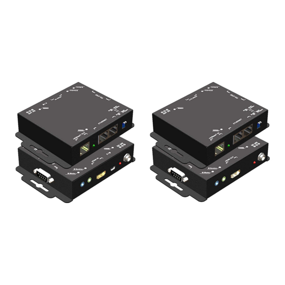
The CV-57VE2-100 includes two units: transmitting unit CV-57VE2-100-TX and receiving unit CV-57VE2-100-RX. The transmitting unit is used to capture the input HDMI / DVI signals with IR control packets. The receiving unit is responsible for equalizing the transmitted HDMI signal and reconstructing IR and serial control signals. -
Page 4: Specifications
SPECIFICATIONS Model Name CV-57VE2-100 Technical CV-57VE2-100[Tx] CV-57VE2-100[Rx] Role of usage Transmitter [TX] Receiver [RX] HDMI compliance HDMI Deep Color, full 3D & 4K2K@30/40m HDCP compliance Video bandwidth Single-link 340MHz [10.2Gbps] Video support 480i / 480p / 720p / 1080i / 1080p60... -
Page 5: Panel Descriptions
PANEL DESCRIPTIONS Transmitting unit ► CV-57VE2-100-TX Front Panel 1. RJ45: Plug in a Cat-5/5e/6 cable that needs to be linked to the transmitting unit RX. 2. LED: TX /RX link indicator 3. Ethernet port for LAN: Connect to network device 4. - Page 6 Receiving unit ► CV-57VE2-100-RX Front Panel 12. RJ45: Plug in a Cat-5/5e/6 cable that needs to be linked to the transmitting unit TX. 13. LED: TX/RX link indicator 14. Ethernet port for LAN: Connect to network device 15. DIP Switch: PIN#1: Setup the RS-232 mode for serial communication channel.
-
Page 7: Ir Pass-Through
IR PASS-THROUGH IR Extenders IR Blaster IR Receiver IR Sockets IR BLASTER: plug in the IR blaster to emit all IR command signals received from the IR receiver from the other enf to control the devices corresponding to the IR signals. IR RECEIVER: plug in the IR receiver to receive all IR command signals from the IR remote controls of the corresponding devices. -
Page 8: Hdmi Pin Definition
1. Connect a HDMI or DVI source (such as a Blu-ray Disc player) to the transmitting unit CV-57VE2-100-TX. 2. Connect a HDMI or DVI display (such as a LCD TV) to the receiving unit CV-57VE2-100-RX. 3. Connect IR Blaster/Receiver to both TX and RX units. -
Page 9: Connection Diagram
CONNECTION DIAGRAM... - Page 10 Software HDBaseT Manager Introduce What is HDBaseT Manager? HDBaseT Manager is the specialized software focusing on detecting the connecting environment and providing in-time investigation on the device that equipped Valens chip inside to find the potential problems in house efficiently and easily. ...
- Page 11 Firmware Check the current firmware version. The upper part reveals the IC type/firmware version on the TX and RX. Update the required firmware In the lower parts, we will see the information as below...
- Page 12 Whenever want to update the firmware, follow the steps as below : Step Action Select Local(TX) or Remote(RX) for firmware Update. Select the firmware file from your PC Review the file information of the selected firmware. Select to get firmware updated and verified at the same time Status (Connecting) *Note: the setting will affect the status page and Brun-in Test function work.
- Page 13 Check the status of connecting In upper part, it will reveal the Valens Mode and Source type. If Connected successfully, you will see the shown as below : Normal If fail to connect, you will get the status as below : Indication radio the light to recognize the connection condition ...
- Page 14 If the status is good, the light should always keep green without yellow or red. If the status is poor, the light will turn to yellow or red.
- Page 15 5. Burn-In Test 5.1 Get the technical file to analyze the unusual situation If the connection is fine, the lines will stay straight all the time. 5.2 If there’s error detected, you will drops as shown below.
- Page 16 Select the required polling period and push to get the data. 5.4 Select and send the file to the engineer for analyzing.
- Page 17 6. Fail-Safe Setting Setting & saving the setting into on board MCU to ensure the stability during transmission. 6.1 Through this manual setting, the device will be able to re-set once the selected conditions are fulfilled at the same time, this will ensure the quality and stability when signals transmission.
- Page 18 6.5 Select the time interval, actually, our device will detect the factors every 0.5 second, if the above trouble (wire quality/ video error) last as long as the set time interval, the device will reset automatically to ensure the good quality in signal transmit. When you choice 30s, that means once the trouble (wire quality/ video error) last for 30s(non-stop), the machine will re-set immediately, that is, if you are in higher tolerance in the time interval of trouble, you can select 40 second or above.
- Page 19 NOTICE 1. All HDMI over CAT5 transmission distances are measured using Belden 1583A CAT5e 125MHz UTP cable and ASTRODESIGN Video Signal Generator VG-859C & VG-870B. 2. Incorrect placement of IR Blaster and Receiver may result in the failure of the IR extenders. Please check carefully before plugging in the IR extender to the respective IR sockets.
-
Page 20: Warranty
The SELLER will NOT be liable for direct, indirect, incidental, special, or consequential damages resulting from any defect or omission in this manual, even if advised of the possibility of such damages. Also, the technical information contained herein regarding the CV-57VE2-100 features and specifications is subject to change without further notice.
Need help?
Do you have a question about the CV-57VE2-100 and is the answer not in the manual?
Questions and answers