Table of Contents
Advertisement
Quick Links
Advertisement
Table of Contents

Related Manuals for Messoa LPR610


Summary of Contents for Messoa LPR610
- Page 1 (IR) Bullet LPR/ANPR Network Camera User Manual 2014-04 615 610 A1...
-
Page 2: Safety Notice
Safety Notice Before using the product, please carefully read through the safety information and operation „ instructions. Safely store the User Manual for future reference. „ When operating the unit, please follow instructions on the User Manual. „ Before cleaning the unit, please first unplug the power. „... -
Page 3: Ce Compliance Statement
CE Compliance Statement This equipment complies with the following requirements of the EMC Directive 2004/108/EC for CE Marking: EN 55022: 2006 + A1: 2007 Class B, EN 61000 and EN 50130. FCC Compliance Statement If the declaration of conformity markings are present on the equipment, the following statements apply: Tested to comply with FCC standards for HOME OR OFFICE USE. -
Page 4: Table Of Contents
Table of Contents Table of Contents Safety Notice ....................... 2 CE Compliance Statement ..................3 FCC Compliance Statement ..................3 WEEE ........................3 1. Overview ....................6 Introduction ......................6 Package Contents....................6 Hardware Overview ....................7 Part Names ......................... 7 Dimensions ......................... - Page 5 Table of Contents 3.3.2 Exposure ......................31 3.3.3 White Balance ....................32 3.3.4 Basic Setting ......................33 3.3.5 Smart Encoding ....................34 3.3.6 Smart Focus .......................34 3.3.7 Privacy Zone ......................35 3.4 Network ....................... 36 3.4.1 Basic .........................36 3.3.2 FTP ........................37 3.3.3 SMTP ........................37 3.3.4 NTP ........................38 3.3.5 RTSP .........................38 3.3.6 ONVIF .......................39 3.4 System ......................
-
Page 6: Overview
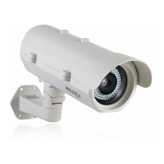
The LPR615 is a 2MP IP LPR camera engineered for detail-demanding traffic surveillance, ranging from access control to high-speed monitoring up to 180km/h. And the LPR610 is a 2MP IR Bullet LPR camera engineered for mid-range traffic surveillance, suitable for LPR applications up to 180km/h. -
Page 7: Hardware Overview
1. Overview Hardware Overview Part Names Top Cover Tempered Glass Tilt Adjustment Screw Bottom Cover Pan Adjustment Screw Bracket The figure above is the illustration of the housing, which may be used with most of ICR real Day and Night cameras. Dimensions Unit: mm User Manual... -
Page 8: Specifications
1. Overview Specifications 10Base-T/100Base-TX Ethernet connection for LAN / Ethernet WAN, RJ-45 ONVIF LPR615 Browser IE Browser 6.0 or Above Security Two-level access with password protection I/O & Controls Video Power Screwless Terminal block Sensor Type 1/2.7" image sensor optimized for low-light performance Power LED Indicator Active Pixels 1920x1080 (HxV) -
Page 9: User Manual
CE, FCC, RoHS White Balance: Auto / Manual; Image Settings Backlight Compensation Ordering Information Configurable Brightness, Contrast, Hue, Saturation, and Sharpness NTSC: LPR610-N2-US-MES; Model No. Gamma Correction PAL: LPR610-P2-EU-MES Digital WDR Yes; 5 level sensitivity Easily adjustable 2-axis and cable-concealed bracket with... -
Page 10: Installation
2. Installation 2. Installation Installation of the Camera and Bracket Wiring Cables 1. Take the bracket from the box and put the power cable and Ethernet cable through the bracket and then fix the bracket to the wall (Loose the screws of the bracket for easy assembly if necessary). - Page 11 2. Installation 3. Put the Ethernet cable through the bottom of the housing and let it pass from the hole. Make connection of power by plugging the terminal block into the power socket. Caution Note For waterproof installation, use the provided spacer and stick it right by the outlet. Then install the three glands to get the power cable and Ethernet cable pass through the hole of the gland covers.
- Page 12 2. Installation 4. Open the side cover and you can see the housing inner part as the figure shown below. I/O board Camera LPR615 Inner Part Definition IR LED driver board I/O board Camera LPR610 Inner Part Definition User Manual...
-
Page 13: I/O Contacts
2. Installation I/O Contacts Connect the power cable to the power port of the AC24V camera and to the A section (L+: power +/ N-: power- ) as below. And connect the outside AC24V power supply to the section B( L+: power+/ N-: power- ). -
Page 14: Recommended Installation Distance
Recommended Installation Distance LPR615 & LPR610 is built in with a 8 ~80mm and 15 ~50mm lens respectively, which can capture a wide 24~26 ft. (7.5~8 meters) field. To ensure an optimal view, please adjust the lens under the conditions we suggest. -
Page 15: Initial Configuration
2. Installation Initial Configuration Before connecting the camera to your network infrastructure, it’s suggested that you connect the camera to a computer first to perform initial configurations. 1. To access the camera, the PC must be on the same network segment as the camera. The default IP address of the camera is a static one (192.168.1.30). -
Page 16: Type 2: Connection To Lan
2. Installation Caution Note Although an RJ-45 coupler is used to extend the connection length, the total length between the PC and the IP camera must not exceed 100 meters (328 feet). The LAN port of the camera supports auto MDI/MDIX (Medium dependent interface crossover) so there is no need to use cross-over cable. -
Page 17: Type 3: Remote Connection Via The Internet
2. Installation Type 3: Remote Connection via the Internet If the network where the camera resides is connected to the Internet, you can also provide remote access to your camera over the Internet. Typically a broadband router has a built-in DHCP function to assign a local IP address to your camera. You can alternatively assign a fixed IP address to the camera to prevent it from frequently changing. -
Page 18: Accessing The Camera For The First Time
2. Installation Accessing the Camera for the First Time The camera comes with a web-based setup utility, allowing you to view the video of the camera and configure the camera for optimal use in your environment. To access the camera’s web-based control utility, you need a PC that meets the following requirements: Operating System: Windows Vista®... - Page 19 2. Installation Step 3: Link Verification between PC and Camera 1. Launch the Command Prompt by clicking the Start menu, Programs, Accessories and then Command Prompt. 2. At the prompt window, type ping x.x.x.x , where x.x.x.x is the IP address of the camera (the default is 192.168.1.30).
-
Page 20: Using "Ip Finder" To Manage Cameras
2. Installation Upon successful login, you will see the live view screen shown below, which is an example for series introduction. Using “IP Finder” to Manage Cameras IP Finder is a management tool included on the product CD. It is designed to manage your network cameras on the LAN. - Page 21 2. Installation The Tool menu of the IP Finder allows you to perform these tasks: Search Network: This option allows you to search the cameras on the network. „ Set Master ID and Password: Allows you to set a master ID and password for managing the „...
- Page 22 2. Installation Network Information: Allows you to configure the camera’s network settings. „ User Manual...
-
Page 23: Web-Based Interface
3. Web-based Interface 3. Web-based Interface 3.1 Overview 3.1.1 Main Screen After you log in to the camera’s web-based control utility, you will first see the live view screen of the camera. The screen below is an example for series introduction. Live view video Camera name Snapshot button... -
Page 24: Setup Menu
3. Web-based Interface 3.1.2 Setup Menu The Setup options are categorized into six groups: ANPR/LPR, Image, Network, System, Event and Recording. Clicking the name will expand its sub-menu. See the ensuing sections for more information. 3.1.3 Applying Settings Each configuration page provides a Save button. Settings are applied right after you press the Save button. -
Page 25: Exposure Mode
3. Web-based Interface Exposure Mode The Exposure Mode allows you to configure the exposure settings to meet the image quality requirements in relation to lighting and other considerations. Auto Exposure Settings Method: Select which area of the image will be used to measure the amount of light to achieve „... - Page 26 3. Web-based Interface Auto IRIS Mode Select Auto IRIS Mode to configure the exposure settings with the auto iris control enabled. Method: Select which area of the image will be used to measure the amount of light to achieve „ best exposure.
- Page 27 3. Web-based Interface Profile Profile Setting provides users with flexibility to customize and apply different parameter settings at up to 4 different time frames in order to meet the variation in light, weather and other environmental factors during a day.(Unavailable when traffic mode is normal) •...
-
Page 28: Image Settings
3. Web-based Interface Auto: Allows the camera to automatically switch between color and black/white modes.(Available „ only when traffic mode is user) Forced B/W: Forces the camera stay in black/white mode at all times. „ Forced Color: Forces the camera stay in color mode at all times. „... - Page 29 3. Web-based Interface H.264 Codec Settings Resolution: Click the drop-down menu to choose a resolution for the video. „ Bit Rate: According to your bandwidth, specify a value for data transmission rate (kbps). Higher „ value gets higher video quality but consumes more bandwidth. Frame Rate: Choose the intended frame rate, i.e., the number of frames to transmit per second.
- Page 30 3. Web-based Interface Refer to the tables below for selectable codec types for each streaming: 2MP Model Streaming Combination Primary Secondary Third Codec Resolution Codec Resolution Codec Resolution 1080P H264 MPEG4 2CIF MJPEG SXVGA MJPEG 720P SVGA H264 MPEG4 2CIF MJPEG 1080P MJPEG...
-
Page 31: Exposure
3. Web-based Interface Mirror Settings This option allows you to mirror or flip the video image if required. OFF: Turns off this function. „ HORIZONTAL: Flips the images horizontally. „ VERTICAL: Flips the images vertically. „ BOTH: Flips the images vertically and horizontally. „... -
Page 32: White Balance
3. Web-based Interface Digital Wide Dynamic Range When there are both very bright and very dark areas simultaneously in the field of view, you can enable Digital Wide Dynamic Range (WDR) function. It optimizes an image to ensure that dark areas are more visible while retaining details in bright areas. -
Page 33: Basic Setting
3. Web-based Interface 3.3.4 Basic Setting The Basic Setting allows you to specify a frequency and adjust the basic image settings to optimize your video image. Frequency: Select an appropriate frequency to reduce the flicker on the image. “50 Hz” and „... -
Page 34: Smart Encoding
3. Web-based Interface 3.3.5 Smart Encoding On the Smart Encoding page you can specify a specific region of the video as more important, i.e., a region of interest (ROI). When a ROI is specified, the camera will assign a higher number of bits to the ROI area to deliver better video quality than non-ROI areas. -
Page 35: Privacy Zone
3. Web-based Interface Basic Settings To focus on a desired subject using the Smart Focus function: 1. Click on the subject that you want to focus on and then click Save Window. 2. Check the Smart Focus Enabled box. This will turn the smart focus indicator to red. 3. -
Page 36: Network
3. Web-based Interface 3.4 Network 3.4.1 Basic DHCP: If there is a DHCP server on the network and you enable this option, the server will „ automatically assign an IP address and related information to the camera. Caution Note If there is no DHCP server on your network or you prefer to manually assign an IP address to the camera, leave the DHCP checkbox blank. -
Page 37: Ftp
3. Web-based Interface 3.3.2 FTP To allow the camera to upload recorded video clips/JPEG files to an FTP server, you have to specify an FTP server and configure related settings. FTP Server IP: Enter the IP address of the FTP server. „... -
Page 38: Ntp
3. Web-based Interface 3.3.4 NTP If you want the camera to synchronize its time clock with an NTP (Network Time Protocol) sever, configure the NTP server settings here. NTP Server: Enter the IP address or the domain name of the NTP server to synchronize with. „... -
Page 39: Onvif
3. Web-based Interface Stream MJPEG Primary rtsp://192.168.1.30:8555/mjpeg MJPEG Third rtsp://192.168.1.30:8558/mjpeg H.264 Primary rtsp://192.168.1.30:8557/h264 H.264 Secondary rtsp://192.168.1.30:8556/h264 MPEG4 Primary rtsp://192.168.1.30:554/mpeg4 MPEG4 Secondary rtsp://192.168.1.30:8554/mpeg4 *Replace the IP address and the port number with the camera’s settings if otherwise configured. 3.3.6 ONVIF ONVIF is a standard that ensures interoperability between IP-based physical security products regardless of the manufacturers. -
Page 40: System
3. Web-based Interface 3.4 System 3.4.1 Date and Time Current Time Displays the current date and time of the camera. Date and time will be updated after you configure new settings in the New Time section and click Save to apply the settings. New Time You can set the camera time by one of the following methods: Set Manually: Manually enter the camera’s date and time settings in the given fields. -
Page 41: Time Stamp
3. Web-based Interface 3.4.2 Time Stamp The Time Stamp function allows you to overlay the date and time stamp on the video. When enabled, the recorded video will be displayed with the date and the time. Enable Date and Time Stamp: Check this box to enable the date and time stamp on images/ „... -
Page 42: User Management
3. Web-based Interface 1. Wait about 20~60 seconds until the file is successfully updated. Once the update is completed, the browser will show a message reads “Firmware update successful”. Then it will take 60 seconds to restart the camera. 2. The utility will automatically go back to live view screen after firmware has been updated successfully. -
Page 43: Language
3. Web-based Interface User List Displays the list of current user accounts of the camera. To delete a user account, select the unwanted user account from the list and then click Delete User. Add/Modify User You can add a new user or modify current user’s account or authority. To add a new user, enter the user name and password and specify the authority. - Page 44 3. Web-based Interface Clear Log File: Click the button to clear the log cache. „ Download Log File: Click the button to save the current log into a text file. When a dialog „ window shows up, click the Save button to locate the directory where the logfile.txt is to be stored.
-
Page 45: Audio
3. Web-based Interface 3.4.7 Audio Audio Receiving: If a microphone is connected to the camera, you can select ON to allow the „ camera to record the audio and transmit to your PC. This enables the camera to pick up sounds in the background. -
Page 46: Event
3. Web-based Interface 3.5 Event When an event occurs, it triggers an alarm and the camera will take a pre-defined action, e.g., sending a recorded video clip or JPEG files to a designated server. With this camera, an event can be triggered by external alarm devices or the camera’s detection mechanism, including motion, blur, audio and Ethernet detection. -
Page 47: External Alarms
3. Web-based Interface Configuration Motion Sensitivity: Specify the sensitivity to moving objects before the camera triggers an „ alarm. The higher the sensitivity, the slighter the movement is required to set off an alarm. You can alternatively select User Define and enter a value from 1 to 100 in the Customized Threshold field. -
Page 48: Face Detection
3. Web-based Interface Action Specify the action to be taken when external alarm is triggered: OFF: No action will be taken, but an alarm will be logged. „ FTP: Recorded video clips/JPEG files will be uploaded to the FTP server when alarm is triggered. „... -
Page 49: Blur Detection
3. Web-based Interface Direction: Select the orientation of faces in the video stream. UP means the top of the face „ is generally in the up direction. The orientation may need to be adjusted when the camera is installed on its side or at an angle. Threshold: Select a face detection acceptance tolerance (High/Medium/Low). -
Page 50: Audio Detection
3. Web-based Interface Sensitivity: You can alternatively customize the camera’s sensitivity to a blur. The camera will „ judge whether it has been tampered based on the sensitivity threshold specified. Action OFF: No action will be taken, but an alarm will be logged. „... -
Page 51: Ethernet Detection
3. Web-based Interface 3.5.6 Ethernet Detection With Ethernet detection enabled, when the camera detects an Ethernet disconnection, the camera will generate an alarm and then take a specified action. Configuration Trigger an Alarm When Ethernet is Disconnected: Select whether to disable/enable this „... -
Page 52: Recording
3. Web-based Interface 3.6 Recording Recording allows you to configure recording-related settings and schedule recording. The defaults are listed in the table below: 3.6.1 Settings – Video File Configure the duration and format of video to be recorded when an alarm is triggered. Basic Settings AVI Duration for FTP Server: Select recorded video duration in seconds for the FTP server. -
Page 53: Settings - Smtp
3. Web-based Interface FTP Networking Displays the current FTP settings, which are specified via Network > FTP. Storage Setting Number of files to upload: Enter the number of JPEG files to be uploaded to the FTP per event. „ File Format: Select the format in which to upload the recorded video file to the FTP server when „... -
Page 54: Sd Card Storage Format Selection
3. Web-based Interface 3.6.4 SD Card Storage Format Selection Storage Setting File Format: Specify the format of the video/picture to be saved to the SD card when an event is „ triggered. Capacity/Usage: Shows the card capacity and the space usage percentage. „... -
Page 55: Period Setting
3. Web-based Interface Besides, users can also just launch the Windows Explorer to access SD card. The same, users are supposed to enter the FTP address (ftp://192.168.1.30 by default) in the address field and finish login process. Then you can directly get into the directory. 3.6.5 Period Setting The Period Setting allows you to schedule video recordings at specified times. -
Page 56: Vlc Player For Rtsp Streaming Access
4. VLC Player for RTSP Streaming Access 4. VLC Player for RTSP Streaming Access Caution Note This information is provided for convenience only. We will not provide support for the installation „ or use of VLC software. The IP addresses used in the document are the default URLs and are provided for example „... - Page 57 4. VLC Player for RTSP Streaming Access The table below lists default URLs. Stream MJPEG Primary rtsp://192.168.1.30:8555/mjpeg MJPEG Third rtsp://192.168.1.30:8558/mjpeg H.264 Primary rtsp://192.168.1.30:8557/h264 H.264 Secondary rtsp://192.168.1.30:8556/h264 MPEG4 Primary rtsp://192.168.1.30/mpeg4 MPEG4 Secondary rtsp://192.168.1.30:8554/mpeg4 6. Click Play and you will see the image streaming. User Manual...
Need help?
Do you have a question about the LPR610 and is the answer not in the manual?
Questions and answers