
Subscribe to Our Youtube Channel
Related Manuals for Messoa LPR615


Summary of Contents for Messoa LPR615
- Page 1 (IR) Bullet LPR/ANPR Network Camera Quick Start Guide P32-615020-000A...
-
Page 3: Safety Instructions
MESSOA assumes no responsibility for errors or omissions that may appear in this document and reserves the right to change this publication at any time without obligation to notify anyone of such revisions or changes. - Page 4 Compliance This equipment complies with the requirements as listed below: FCC Part 15 Class A „ CE: 2004/108/EC-Electromagnetic Compatibility (EMC) directive based on „ EN55022: 2010 Class A, EN61000 and EN55024 standard. WEEE Waste Electrical and Electronic Equipment Correct disposal of this product (applicable in the European Union and other European countries with separate collection systems).
-
Page 5: Package Contents
1. Introduction This quick start guide is intended to provide installers with basic instructions for installing and configuring the Network Traffic Camera. For more detailed information of using and configuring the product, please refer to the User Manual available on the provided CD-ROM. 1.1 Package Contents Check the items supplied with your network traffic camera against the following list. -
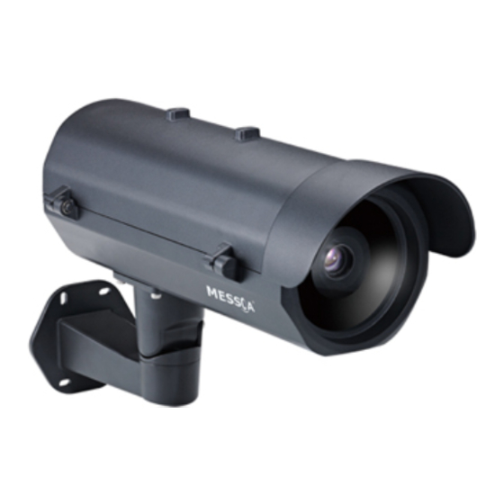
Page 6: Hardware Overview
1.2 Hardware Overview Part Names Top Cover Tempered Glass Tilt Adjustment Screw Bottom Cover Pan Adjustment Screw Bracket The figure above is the illustration of the housing, which may be used with most of ICR real Day and Night cameras. Dimensions Unit: mm Quick Start Guide... -
Page 7: Installation Of The Camera And Bracket
2. Installation Installation of the Camera and Bracket Wiring Cables Take the bracket from the box and put the power cable and Ethernet cable through the bracket and then fix the bracket to the wall (Loose the screws of the bracket for easy assembly if necessary). Take out the housing and open the side cover with the hexagonal wrench. - Page 8 Put the Ethernet cable through the bottom of the housing and let it pass from the hole. Make connection of power by plugging the terminal block into the power socket. Note For waterproof installation, use the provided spacer and stick it right by the outlet. Then install the three glands to get the power cable and Ethernet cable pass through the hole of the gland covers.
- Page 9 Open the side cover and you can see the housing inner part as the figure shown below. I/O board Camera LPR615 Inner Part Definition Quick Start Guide...
- Page 10 IR LED driver board I/O board Camera LPR610 Inner Part Definition Quick Start Guide...
- Page 11 I/O Contacts Contact positions on the heater board Connect the power cable to the power port of the AC24V camera and to the A section (L+: power +/ N-: power- ) as above. And connect the outside AC24V power supply to the section B( L+: power+/ N-: power- ). Quick Start Guide...
- Page 12 After you have finished wiring the Ethernet cable, close the side cover and use the provided screws to fix the housing on the bracket with the hexagonal wrench. Loosen the pan and tilt adjustment screws of the bracket to adjust the angle of the housing and then tighten the screws.
-
Page 13: Recommended Installation Distance
Recommended Installation Distance LPR615 & LPR610 is built in with a 8 ~80mm and 15 ~50mm lens respectively, which can capture a wide 24~26 ft. (7.5~8 meters) field. To ensure an optimal view, please adjust the lens under the conditions we suggest. -
Page 14: Initial Configuration
3. Initial Configuration Before connecting the camera to your network infrastructure, it’s suggested that you connect the camera to a computer first to perform initial configurations. To access the camera, the PC must be on the same network segment as the camera. -
Page 15: Connecting To Your Network
4. Connecting to Your Network There are many different ways that you can connect the camera to your network, depending on your applications requirements. You should always set the camera’s network settings according to your network configurations. The following diagrams depict some typical applications with guidelines on network settings. For more information on network settings, always consult with your network administrator or ISP as required. -
Page 16: Type 2: Connection To Lan
Type 2: Connection to LAN To add the camera(s) to an existing LAN, just connect the camera(s) to the router, switch or hub on your network. Note The LAN port of the camera supports auto MDI/MDIX (Medium dependent interface crossover) so there is no need for an uplink port or the use of a cross- over cable. -
Page 17: Type 3: Remote Connection Via The Internet
Type 3: Remote Connection via the Internet If the network where the camera resides is connected to the Internet, you can also provide remote access to your camera over the Internet. Typically a broadband router has a built-in DHCP function to assign a local IP address to your camera.
Need help?
Do you have a question about the LPR615 and is the answer not in the manual?
Questions and answers