
Related Manuals for Motorola DCX3520E-M


Summary of Contents for Motorola DCX3520E-M
- Page 1 - Cablevision notice - The instructions in this guide are also valid for the DCX3520E-M model.
- Page 2 Installation Manual DCX3510-M High-Definition DVR...
- Page 3 ©2011 Motorola Mobility, Inc. All rights reserved. No part of this publication may be reproduced in any form or by any means or used to make any derivative work (such as translation, transformation, or adaptation) without written permission from Motorola, Inc. Motorola reserves the right to revise this publication and to make changes in content from time to time without obligation on the part of Motorola to provide notification of such revision or change.
-
Page 4: Safety & Regulatory Information
Safety & Regulatory Information Safety & Regulatory Information IMPORTANT SAFETY INSTRUCTIONS Read these instructions. Keep these instructions. Heed all warnings. Follow all instructions. Do not use this apparatus near water. Clean only with dry cloth. Do not block any ventilation openings. Install in accordance with the manufacturer’s instructions. Do not install near any heat sources such as radiators, heat registers, stoves, or other apparatus (including amplifiers) that produce heat. -
Page 5: Fcc Compliance
Connect the equipment into an outlet on a circuit different from that to which the set-top is connected. Consult the dealer or an experienced radio/TV technician for help. Caution: Changes or modifications not expressly approved by Motorola for compliance could void the user’s authority to operate the equipment. -
Page 6: Fcc Declaration Of Conformity
Safety & Regulatory Information FCC Declaration Of Conformity Motorola Mobility, 101 Tournament Drive, Horsham, PA 19044, 1-215-323-1000, declares that the DCX 3510 set-top complies with 47 CFR Parts 2 and 15 of the FCC rules as a Class B digital device. -
Page 7: Software License
Software. The Software is never sold. Motorola licenses the Software to the original customer and to any subsequent licensee for personal use only on the terms of this License. Motorola and its third party licensors retain the ownership of the Software. - Page 8 License. Motorola is not responsible for any third party software that is provided as a bundled application, or otherwise, with the Software or that is downloaded to, or otherwise installed on, the Product.
-
Page 9: Table Of Contents
Contents Contents Safety & Regulatory Information ....................i Software License .......................... iv Tables .............................. 3 Figures ............................3 Introduction ............................ 5 Features ............................6 Tuners ............................6 Standard Audio/Video Features ....................6 Standard DVR Functionality....................... - Page 10 Contents Connecting an A/V Receiver, SDTV, and VCR ................27 Connecting to an External eSATA DVR/Hard Drive ............... 29 Data Device Connections ......................30 Data Features .......................... 30 Operational Check for the Remote Control ................... 31 ...
-
Page 11: Tables
Tables Tables Table 1: DVR recording time guidelines ..................7 Table 2: Audio Connection Options ....................16 Table 3: Operational check procedures ..................31 Table 4: User Settings—Main Menu Field Descriptions ............... 35 Table 5: Native Mode Settings Field Descriptions ................ 39 ... - Page 12 Figures Figure 8: Connecting a Standard-Definition TV (SDTV) and VCR/DVD Recorder ......26 Figure 9: Connecting an A/V Receiver, SDTV, and VCR ..............28 Figure 10: Connecting to an External eSATA DVR/Hard Drive ............29 Figure 11: Examples of Data Devices You Can Connect to the DCX3510-M ....... 30 ...
-
Page 13: Introduction
Ethernet and Universal Serial Bus (USB) 2.0 ports for future home networking applications Adaptability to various software platforms As with all Motorola digital cable set-tops, the hardware features are enabled by core operating and third party application software. High-Definition DVR DCX3510-M Installation Manual 365-095-17066-x.1... -
Page 14: Features
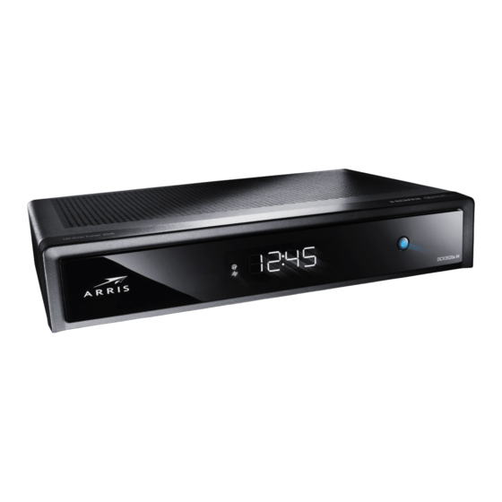
Introduction Figure 1: Front and rear views Features Tuners Two all-digital 1 GHz (54 to 1002 MHz) video tuners MPEG-2 Main Profile @ High Level (High-Definition) MPEG-4 H.264 (AVC) High-Definition decode One dedicated tuner for the DOCSIS high-speed data services channel, up to 1 GHz One dedicated tuner for the out-of-band (OOB) control channel Standard Audio/Video Features ITU standard 64/256 QAM/FEC/enhanced adaptive equalizer... -
Page 15: Standard Dvr Functionality
Motorola cannot guarantee the exact amount of programming that each subscriber will be able to record. The approximate time depends on the programming type and the drive... -
Page 16: Standard Data Features
Outside the U.S.: 1-847-725-4011 Motorola Mobility Online (MOL): http://mobilityonline.motorola.com. The TRC is on call 24 hours a day, 7 days a week. In addition, Motorola Online offers a searchable solutions database, technical documentation, and low-priority issue creation and tracking. For specific toll-free numbers when calling from outside the United States, please refer to the product manual or our web page. -
Page 17: Calling For Repairs
Introduction Calling for Repairs If a Motorola set-top requires repair service, please call one of the following Motorola Authorized Service Centers: Company From USA or Canada Outside USA or Canada World Wide Digital 1-800-227-0450 1-956-541-0600 Teleplan 1-800-352-5274 1-302-322-6088 To ensure efficient service, request a Return for Service Authorization (RSA) number. Be sure to display the RSA number prominently on all equipment boxes. -
Page 18: Overview
Overview Overview Front Panel The DCX3510 is streamlined with only a mechanical power button on the front panel to turn the set-top on and off. Certain functions, such as those requiring a numeric entry or accessing menus, require a remote control. Figure 2: Front panel Number Description... -
Page 19: Video Format Indicators (Front Panel Display)
Overview Video Format Indicators (Front Panel Display) The front panel display of the DCX3510-M set-top is equipped with indicators to the right hand side of the display that are used to indicate the currently-selected video output format on the component video (YPbPr) and HDMI outputs. The DCX3510-M set-top is capable of providing the following video formats on the YPbPr and HDMI video outputs: High Definition 1080i (1920 x 1080 pixels) -
Page 20: Rear Panel
Installation Rear Panel Figure 3: Rear Panel Number Description Cable In — Connects to cable signal from your service provider ® Digital Audio (Optical S/PDIF) — Provides Dolby Digital or PCM output Video outputs / YPbPr — Component video output (HDTV) Audio Out —... -
Page 21: Installation
If the terminal was previously used, clear its hard drive before installing it at a new subscriber location. Cold Reset Procedure This section describes the Cold Reset procedure for Motorola’s DCX3510-M set-top. The cold reset is generally used by operational and field personnel to accomplish the following: Restore the set-top to a known state. -
Page 22: Clearing The Hard Drive
Installation Clearing the Hard Drive On a previously-used cable terminal, delete all recorded programs from the hard drive before installing it at a new subscriber location. This prevents the new subscriber from viewing programming they may not have purchased or may not want to see. To prevent subscribers from accidentally deleting all of their recorded programs, a specific set of keystrokes is required to clear the hard drive. -
Page 23: Video Connection Options
Installation Video Connection Options Use the following guidelines to determine the best video connection for the subscriber home entertainment system. To determine the available video inputs on the TV, check the manual supplied with the TV or the TV itself. The DCX3510-M offers the following video outputs: Connection Type TV Type... -
Page 24: Audio Connection Options
This is important when the subscriber has another A/V device such as a DVD player, secondary VCR, CD player, or other electronic component. Motorola recommends connecting the TV to the monitor output so on-screen menus for the receiver can be displayed. -
Page 25: Installation Overview
Installation Installation Overview 1. Determine if you are connecting to a: a. High-Definition TV or monitor: Use the component video (YPbPr), HDMI, or IEEE-1394 outputs. No other video connection supports HDTV. If the TV has a DVI input, connect a DVI-to-HDMI adapter or cable to the HDMI out connector on the DCX set-top instead of the IEEE-1394 connection and the DVI-HDTV connector on the TV. -
Page 26: Connecting An Hdtv - Single Connection For Video/Audio
Installation Connecting an HDTV — Single Connection for Video/Audio This section describes steps to connection the DCX to an HDTV using connection options that combine video and audio into a single cable. Cable In Connect an RF coaxial cable to the cable wall outlet and the cable in connector on the DCX set-top. -
Page 27: Figure 4: Connecting An Hdtv - Single Connection For Video/Audio
Installation Figure 4: Connecting an HDTV — Single Connection for Video/Audio Note: Only (1) HDTV video/audio connection needs to be made to an HDTV. Note: On-screen graphics will not be displayed when using IEEE-1394 connection. Refer Graphics Overlaying the Video for more information. -
Page 28: Connecting An Hdtv - Separate Video/Audio Connections
Installation Connecting an HDTV — Separate Video/Audio Connections Cable In Connect an RF coaxial cable to the cable wall outlet and the cable in connector on the DCX set-top. If the TV has a DVI input, use the DVI connection for the video: Connect a HDMI-to-DVI adapter or cable to the HDMI out connector on the DCX set- top and the DVI-HDTV connector on the TV. -
Page 29: Figure 5: Connecting An Hdtv - Separate Video/Audio Connections
Installation Figure 5: Connecting an HDTV — Separate Video/Audio Connections Note: If the receiver can check the baseband and digital audio (S/PDIF) ports for appropriate channels, connect both the baseband and digital audio connections. Otherwise, do not connect both the baseband left/right composite connections and the coaxial digital connection. -
Page 30: Connecting An A/V Receiver - Audio
Installation Connecting an A/V Receiver — Audio There are several options available for audio connections to the A/V receiver: Digital audio (OPTICAL S/PDIF) Stereo audio (AUDIO L and R) optical S/PDIF If the A/V receiver supports it, the digital audio output may be used in audio L place of the stereo audio outputs ( ). -
Page 31: Figure 6: Connecting An A/V Receiver - Audio
Installation Figure 6: Connecting an A/V Receiver — Audio Note: This connection method does not support HDTV. For information, see Connecting an HDTV — Separate Video/Audio Connections in this section. High-Definition DVR DCX3510-M Installation Manual 365-095-17066-x.1... -
Page 32: Connecting A Standard-Definition Tv (Sdtv)
Installation Connecting a Standard-Definition TV (SDTV) AUDIO L 1. Connect the stereo audio cable to the connectors on the DCX3510- AUDIO L M series set-top and the connectors on the SDTV. VIDEO OUT 2. Connect a video cable to the connector on the DCX3510-M series set- INPUT VIDEO top and the... -
Page 33: Connecting A Standard-Definition Tv (Sdtv) And Vcr/Dvd Recorder
Installation Connecting a Standard-Definition TV (SDTV) and VCR/DVD Recorder 1. Connect a stereo audio cable to the AUDIO OUT L and R connectors on the DCX3510-M and the INPUT AUDIO L and R connectors on the VCR/DVD Recorder. VIDEO OUT 2. -
Page 34: Figure 8: Connecting A Standard-Definition Tv (Sdtv) And Vcr/Dvd Recorder
Installation Figure 8: Connecting a Standard-Definition TV (SDTV) and VCR/DVD Recorder High-Definition DVR DCX3510-M Installation Manual 365-095-17066-x.1... -
Page 35: Connecting An A/V Receiver, Sdtv, And Vcr
Installation Connecting an A/V Receiver, SDTV, and VCR 1. Connect a stereo audio cable to the AUDIO OUT L/R connectors on the DCX3510-M series set-top and the INPUT L/R connectors on the A/V receiver. 2. Connect a composite video cable to the composite video out connector on the DCX3510-M series set-top and the composite video connector on the A/V receiver. -
Page 36: Figure 9: Connecting An A/V Receiver, Sdtv, And Vcr
Installation Figure 9: Connecting an A/V Receiver, SDTV, and VCR Note: Solid lines indicate optimum connections. Note: Consult your A/V receiver manual for additional wiring options or constraints when including a VCR/DVD Recorder in your configuration. High-Definition DVR DCX3510-M Installation Manual 365-095-17066-x.1... -
Page 37: Connecting To An External Esata Dvr/Hard Drive
5. Connect the other end of the eSATA cable to the external drive. 6. Follow the on-screen instructions. Note: Only connect external hard drives that have been approved by Motorola for external DVR service. Connecting an external drive that has not been approved could result in poor DVR performance. -
Page 38: Data Device Connections
Installation Data Device Connections Figure 11: Examples of Data Devices You Can Connect to the DCX3510-M Do not attempt to connect data devices without contacting your service provider. Advanced data features require the proper application and network infrastructure to operate. Data Features In addition to high-quality audio and video, the DCX3510-M can deliver high-speed data services such as Internet access, e-mail, IP telephony, e-commerce, and home banking. -
Page 39: Operational Check For The Remote Control
Installation Operational Check for the Remote Control The operational check tests communication with the remote control: Table 3: Operational check procedures Feature Testing Procedure Power on Press power on the remote control to turn on the DCX3510-M. Tune to the output channel (3 or 4), if using the RF output. Channel Scan through the channels using the channel + or - keys. -
Page 40: Configuring The User Settings
Configuring the User Settings Configuring the User Settings Configuring the User Settings The following describes how to configure the audio (for HDMI connections), SD and HD video, closed caption, subtitle, and power settings for the DCX3501-M. Before you adjust the output settings: 1. -
Page 41: User Settings Menu Main Screen
Configuring the User Settings User Settings Menu Main Screen To configure the DCX3510-M settings on the main User Settings menu screen, first power off the DCX3510-M using either the remote control or the Power button and then press the MENU key on the remote control. If the TV is on, the on-screen User Settings menu lists the DCX3510-M settings that can be adjusted. -
Page 42: Figure 13: Default User Settings Menu -With Hdmi Connection
Configuring the User Settings Figure 13: Default User Settings Menu —With HDMI Connection Use the remote control cursor keys to navigate the on-screen menus as follows: Press the keys to highlight the setting you wish to change. Press the key to select an option. To exit the setting and move to another setting, press the key. -
Page 43: Table 4: User Settings-Main Menu Field Descriptions
Configuring the User Settings Table 4: User Settings—Main Menu Field Descriptions Setting Description TV Type Allows you to specify the style of television connected to the DCX3510-M. The 16:9 option is the default. 16:9— A widescreen television is connected to the DCX3510-M. 4:3 Letterbox —... - Page 44 Configuring the User Settings Setting Description 4:3 Override Allows you to select the video output format of the DCX3510-M when it is tuned to a Standard-Definition program or playing back a Standard- Definition program from the DVR. The 480i option is the default. 480i—Standard-Definition 480i format (720 x 480 pixels).
- Page 45 Configuring the User Settings Setting Description Additional Allows you to customize the style and appearance of closed captions. Closed Selecting this presents a new menu screen with settings specific to closed Caption captions, including font style, color, and size. These settings are discussed in Settings more detail below.
-
Page 46: Native Mode Settings Screen
Configuring the User Settings Native Mode Settings Screen The Native Mode Settings menu configures the operation of the native mode feature on the DCX3510-M. The DCX3510-M can receive and decode a number of different digital video formats. When operating in native mode, the DCX3510-M generates the video output format that most closely matches the broadcast video format. -
Page 47: Table 5: Native Mode Settings Field Descriptions
Configuring the User Settings Table 5: Native Mode Settings Field Descriptions Setting Description Generates 1080p60 video on the HDMI output if the program is broadcast in 1080p60 1080p60 format. The DCX3510-M can also convert any other broadcast format (High Definition) to the 1080p60 video format. - Page 48 Configuring the User Settings Setting Description Generates 480p video on both the HDMI and Component Video (YPbPr) 480p outputs if the program is broadcast in 480p format. The DCX3510-M can also (Enhanced convert any other broadcast format to the 480p video format. Definition) 480p is an enhanced-definition video image with 720 x 480 pixels, progressive scanning, and a frame rate of 60 frames per second.
-
Page 49: Additional Hdmi Settings Screen
Configuring the User Settings Additional HDMI Settings Screen The Additional HDMI Settings menu configures advanced options that affect the operation of the DCX3510-M with other HDMI and DVI display devices. Adjustable options include display mode, color space, audio output mode, and audio lip sync delay. Figure 16: Additional HDMI Settings Screen High-Definition DVR DCX3510-M Installation Manual... -
Page 50: Table 6: Additional Hdmi Settings Field Descriptions
Configuring the User Settings Table 6: Additional HDMI Settings Field Descriptions Setting Description Allows you to optimize the HDMI output to work with both DVI-equipped HDMI/DVI Mode televisions and HDMI-equipped televisions. HDMI is the default setting. HDMI—Optimized to work with an HDMI television or home theater receiver. DVI—Optimized to work with a DVI television or display device (connected via an HDMI-to-DVI adapter). - Page 51 Configuring the User Settings Setting Description Available when the Lip Sync option has been set to Manual. Lip Sync Delay The Lip Sync Delay setting can be adjusted between 0 milliseconds and 500 milliseconds in 50 millisecond increments. If the Lip Sync option has been set to either Auto or Off, this option is disabled and can’t be selected in the menu.
-
Page 52: Additional Closed Caption Settings Screen
Configuring the User Settings Additional Closed Caption Settings Screen The Additional Closed Caption Settings menu adjusts the various display options for closed caption legibility. Customizable options include font size, font style, font color, and font opacity. You may also choose to view different closed caption services if these are included within the broadcast program. -
Page 53: Table 7: Additional Closed Caption Settings Field Descriptions
Configuring the User Settings Table 7: Additional Closed Caption Settings Field Descriptions Setting Description Sets the service used by the DCX3510-M to render (draw) the closed captions: Service Selection Analog—Affects closed captions for analog and digital standard definition services. Available options are: CC1, CC2, CC3, CC4, T1, T2, T3, or T4. The default setting is CC1. -
Page 54: Subtitle And Dvs Settings Screen
Configuring the User Settings Subtitle and DVS Settings Screen The Subtitle and DVS Settings menu customizes the language and appearance of subtitles and turns the descriptive video service feature on and off. Subtitles allow a viewer to watch television programs and movies that contain dialogue that is not in the viewer’s native language. -
Page 55: Table 8: Subtitle And Dvs Settings Field Descriptions
Configuring the User Settings Table 8: Subtitle and DVS Settings Field Descriptions Setting Description Subtitles The default setting is Off. Off—Subtitles are not rendered (drawn) by the DCX3510-M. On—Subtitles are rendered (drawn) by the DCX3510-M if they are included in the program and in the language specified by the Language setting. -
Page 56: Advanced Audio/Video Settings Screen
Configuring the User Settings Advanced Audio/Video Settings Screen The Advanced Audio/Video Settings menu customizes several advanced audio and video features of the DCX3510-M, most notably the Dolby Volume feature and the Video Sharpness feature. The Dolby Volume feature provides volume normalization across channels, programs, and commercials. -
Page 57: Graphics Overlaying The Video
Configuring the User Settings Table 9: Advanced Audio/Video Settings Field Descriptions Setting Description Dolby Volume The default setting is Off. Off—Output volume may fluctuate during commercials or when changing channels. On—Maintains a more consistent output volume regardless of the channel or program being viewed. -
Page 58: Diagnostics
Diagnostics Diagnostics Diagnostics are displayed on the on-screen display (OSD) and front-panel display. They confirm proper installation, including: Checking error states and signal integrity Identifying the cable terminal on the network Verifying communications with the headend For the diagnostics described in this section: All indicators are in decimal notation, unless otherwise noted. -
Page 59: General Status
Diagnostics Figure 20: Diagnostic Main Menu Screen General Status This diagnostic displays system status information on the OSD and front panel. The information is updated each time the diagnostic is displayed. Figure 21: General Status Diagnostic Screen High-Definition DVR DCX3510-M Installation Manual 365-095-17066-x.1... -
Page 60: Table 10: General Status Diagnostic Field Descriptions
Diagnostics Environment code Error code Figure 22: Example General Status display (no error) Table 10: General Status Diagnostic Field Descriptions Field Description Error Error codes display on the LED and OSD when an error occurs. If multiple errors occur, the last recorded error is displayed: Error Code Description EP00... -
Page 61: Purchase Status
Diagnostics Field Description Remod Chan Set-top Local Time The current time setting on set-top. DST Active Daylight Saving Time. Yes indicates the DST is active. No indicates the DST is disabled. Time Zone Time Zone is selected on the set-top. DST Entry Time The Date and Time the set-top will begin Daylight Savings Time. -
Page 62: Table 11: Purchase Status Diagnostic Field Descriptions
Diagnostics Purchase Indicator On when IPPV is Number of enabled unsent purchases Figure 24: Front panel display for Purchase Status diagnostic Table 11: Purchase Status Diagnostic Field Descriptions Field Description Unsent The number of purchases in the DCX3510-M remaining to be polled. It can be an integer from 0 to 63. -
Page 63: Out-Of-Band (Oob) Status
Diagnostics Field Description Debit Total Debit used for purchase processing. Out-Of-Band (OOB) Status This diagnostic indicates the out-of-band control channel status. The information is updated every five seconds. Figure 25: OOB Status Diagnostic Screen Data activity EMM data activity indicator indicator Carrier lock indicator (L = locked, U = unlocked) -
Page 64: Table 12: Oob Diagnostic Field Descriptions
Diagnostics Table 12: OOB Diagnostic Field Descriptions Field Description OOB Frequency Indicates the OOB tuner center frequency, from 70 to 130 MHz. Carrier Lock Indicates whether the OOB receiver is locked to the carrier: Front panel Description Carrier locked Carrier unlocked Data Indicates whether data is being carried by the OOB and EMM traffic, which is tracked separately:... -
Page 65: Agile Oob Tuner Hunting
Diagnostics Field Description hexadecimal. Network PID Displays the network PID to which the DCX3510-M is tuned to receive network messages, in hexadecimal. Hunt Mode The hunt mode includes Hunted, None, Round Robin (RR), Search (SRCH), Fixed Frequency (FIX), or EMM Provider ID (EMM). The last known carrier is the last valid OOB frequency displayed in MHz and ranges from 70 to 130 MHz, with the specific values of: 75.25, 104.20, 72.75, 92.25, 98.25, 107.25, 107.40, 110.25, 116.25, and 103.75. - Page 66 Diagnostics 4. If the frequency is found with the proper EMM Provider ID, then the Front Panel displays the normal OOB receiver status. The OSD LKC field changes to display the new frequency. 5. If after 40 seconds the frequency search is not successful, the product performs a warm reset.
-
Page 67: In-Band Status
Diagnostics In-Band Status This diagnostic displays the in-band status for the last attempted tuned channel. The information is updated every five seconds. Figure 27: In-Band Status Diagnostic Screen Data activity indicator IB diagnostic Carrier lock indicator indicator (L = locked, U = unlocked) Figure 28: Front panel display for in band diagnostic High-Definition DVR DCX3510-M Installation Manual... -
Page 68: Table 13: In-Band Status Diagnostic Field Descriptions
Diagnostics Table 13: In-Band Status Diagnostic Field Descriptions Field Description Mode The values displayed on the OSD are: 64 QAM — 64 QAM digital channel 256 QAM — 256 QAM digital channel Carrier Indicates whether the in-band receiver is locked to the carrier. If a digital carrier is not present, Lock it indicates the carrier is not locked: Front panel... -
Page 69: Unit Address
Diagnostics Unit Address This diagnostic displays the unit address of the CableCARD if inserted: Figure 29: Unit Address Diagnostic Screen Figure 30: Front panel display of a unit address High-Definition DVR DCX3510-M Installation Manual 365-095-17066-x.1... -
Page 70: Table 14: Unit Address Diagnostic Field Descriptions
Diagnostics Table 14: Unit Address Diagnostic Field Descriptions Field Description TvPC Installed Indicates whether the TvPC renewable security system is installed: NO — TvPC is not installed (Note: the DCX3510-M does not include a TvPC slot). CableCARD YES — CableCARD is inserted. Inserted NO —... -
Page 71: Separable Security
Diagnostics Separable Security This diagnostic displays information on the inserted M-CARD and CableCARD Interface with the DCX. Figure 31: Separable Security Diagnostic Screen Table 15: Separable Security Diagnostic Field Descriptions Field Description CARD Interface CableCARD Interface is a status indication of the interface between the Host and CableCARD. - Page 72 Diagnostics MSO Phone Number as configured at the headend. MSO Phone Number CableCARD Object Name Code object name executing on the CableCARD. Object Ver. Code object version executing on the CableCARD. Manufacturer CableCARD manufacturer. HW Version Version number provided by the CableCARD. Boot Version Version number provided by the CableCARD.
-
Page 73: Current Channel Status
Diagnostics Current Channel Status This diagnostic displays a status of the last attempted channel you attempted to tune on the in-band stream. The channel type determines the status display. Figure 32: Current Channel Status Diagnostic Screens Digital channel: Purchasable indicator Preview indicator Digital channel indicator Epoch authorization code Figure 33: Current Channel Status Front Panel Displays... -
Page 74: Table 16: Current Channel Status Diagnostic Field Descriptions
Diagnostics Table 16: Current Channel Status Diagnostic Field Descriptions Description Field Type Indicates whether the channel is analog or digital. Front Description panel DIGITAL Digital Status Indicates the current status of channel acquisition. Front Description panel Acquired Service has been acquired and is playing, but stream components may not be locked yet if the service is digital. - Page 75 Diagnostics Field Description Tuned (Digital channels only) The center RF carrier frequency for the digital service. It can be Frequency From 54 to 860 MHz. VCT ID Virtual Channel Table ID The Selectable Output control is enabled or disabled. The copy control information: 00 —...
-
Page 76: Rf Modem (Upstream)
Diagnostics Field Description MotoCar configuration and message count Version number of the SDV configuration message and number of minutes since the version was last seen by the client Configured switched channels (SW) followed by the number of channels in the Active Channel List (ACL). -
Page 77: Figure 35: Rf Upstream Modem Front Panel Display
Diagnostics Frequency Decimal point Frequency in Alternating with Power level Power level in dB (blank if modem not configured) Figure 35: RF Upstream Modem Front Panel Display High-Definition DVR DCX3510-M Installation Manual 365-095-17066-x.1... -
Page 78: Code Modules
Diagnostics Table 17: RF Upstream Modem Diagnostic Field Descriptions Field Description Status CONFIGURED or NOT CONFIGURED. Center The RF modem center frequency is displayed on the OSD and front panel in MHz. Frequency Requested The value in dB assigned to the DCX3510-M during RF leveling (which is blank if it is not Power configured). -
Page 79: Figure 37: Front Panel Display For Code Modules
Diagnostics Download data Download received indicator Number of segments remaining for download to complete. (Figure reflects 17012 segments Code module identifier (bPC for the base platform; CODE or SYS for the system object Alternating Indicator separating major and minor Figure 37: Front Panel Display For Code Modules High-Definition DVR DCX3510-M Installation Manual 365-095-17066-x.1... -
Page 80: Table 18: Code Modules Diagnostic Field Descriptions
Diagnostics Table 18: Code Modules Diagnostic Field Descriptions Field Description Boot Code The boot code version in ASCII format. Platform Built The date platform software was built. Version The firmware version and build date in ASCII format. Processor The digital secure processor version in ASCII format. Analog The analog secure processor version in ASCII format. - Page 81 Diagnostics Field Description POSTPONED Postponed The Object cannot run on the current system; it will be enabled during the next boot. CONNECTED Connect Connected to download PID — awaiting data. PEND CONNECT TryingToConnect Trying to connect. The object identifier. The Local Origination states whether the object is located locally on the set-top. High-Definition DVR DCX3510-M Installation Manual 365-095-17066-x.1...
-
Page 82: Memory Configuration
Diagnostics Memory Configuration This diagnostic displays the DCX3510-M memory configuration. The information is updated when you display the diagnostic. Figure 38: Memory Configuration Diagnostic Screen Note: There is no front panel display for this diagnostic. Table 19: Memory Configuration Diagnostic Field Descriptions Field Description System RAM... -
Page 83: Table 20: Audio/Video Status Diagnostic Field Descriptions
Diagnostics Figure 39: Audio/Video Status Diagnostic Screen Table 20: Audio/Video Status Diagnostic Field Descriptions Field Description S/PDIF Output Indicates S/PDIF Mode as set by application software. OSD Display Description Audio S/PDIF mode is not applicable. IEC958PCM PCM audio selected. Dolby Digital Dolby Digital uses the following speaker selections: Right front or left front Right front and left front... - Page 84 Diagnostics Field Description Dolby Volume Indicates if Dolby Volume is turned on or off Audio / Video The Audio and Video Mute Status indicates if the audio and/or video have been muted Mute by the software. The audio mute is either On or Off. The Video Mute describes the MPEG muting method selected by the software and indicates if the output video is in the mute state by displaying On or Off, followed by the mute method.
- Page 85 Diagnostics Field Description Closed Caption service T 1 Closed Caption service T 2 Closed Caption service T 3 Closed Caption service T 4 OSD Display Description Primary Lang Primary language set by the provider (default, Service 1). Second Lang Secondary language set by the provider (Service 2). Service 3 Set by the provider Service 3.
-
Page 86: Interface Status
Diagnostics Interface Status The Interface Status diagnostic displays when running in Thin Client. There is no LED display. The information on the OSD is updated when you display the diagnostic. Figure 40: Interface Status Diagnostic Screens High-Definition DVR DCX3510-M Installation Manual 365-095-17066-x.1... -
Page 87: Table 21: Interface Status Diagnostic Field Descriptions
Diagnostics Table 21: Interface Status Diagnostic Field Descriptions Field Description DOCSIS Tuner & Indicates if enabled; indicates if active. Xmitter 1394 I/O Device Indicates if enabled; indicates if active. USB I/O Device Indicates if enabled; indicates if active. Ethernet Device Indicates if enabled;... -
Page 88: Dvr/Hard Drive Status
Diagnostics Field Description employed on the 1394 interface Copy Control - level of copy control in the 1394 content. Valid values include: ‘Copy Free’, ‘Copy Once’, ‘No Copies’, ‘Copy Never’. Nodes - indicates if the set-top terminal is the cycle master node, the IRM node, and/or the root node on the 1394 bus. -
Page 89: Table 22: Dvr/Hard Drive Status Diagnostic Field Descriptions
Diagnostics Table 22: DVR/Hard Drive Status Diagnostic Field Descriptions Field Description Enabled Indicates whether the DVR is enabled, based on the DCX3510-M Connected State (CONNECTED or DISCONNECTED) and resource availability (resource authorized; hard disk installed and functional): Front panel Description True DVR enabled Front Panel... - Page 90 Diagnostics Field Description State The hard drive state: Standby — The hard drive is working normally, but is at rest (the State returns to Active any time disc access is necessary). Active — The hard drive is accessing data. Failed — The hard drive hardware has failed. Temp (F) For an internal hard drive only, its temperature in degrees F.
-
Page 91: Docsis Status
Diagnostics DOCSIS Status This three-screen diagnostic displays status information for the embedded cable modem (eCM): Figure 42: DOCSIS Status Diagnostic Screens Table 23: DOCSIS Status Diagnostic Field Descriptions Field Description DOCSIS Enabled For a DOCSIS-enabled set-top, YES. Otherwise, NO. Acquire DS Channel The DOCSIS downstream channel acquisition status: YES —... - Page 92 Diagnostics Field Description N/A — The value is invalid or cannot be retrieved, or DOCSIS is not enabled. Establish IP Displays whether the cable modem has acquired its IP address, typically from a Connectivity Dynamic Host Configuration Protocol (DHCP) server: YES —...
- Page 93 Diagnostics Field Description NO — The cable modem is not locked to a downstream channel. N/A — The value is invalid or cannot be retrieved, or DOCSIS is not enabled. Frequency The center frequency of the channel to which the DOCSIS downstream channel receiver is tuned.
-
Page 94: Application Specific Information
Diagnostics Application Specific Information This diagnostic displays information about application servers: Figure 43: Application Specific Information Diagnostic Screen Table 24: Application Specific Information Diagnostic Field Descriptions Field Description Server# Name The application server name of up to 14 alphanumeric characters. It is blank if the value is invalid or no value can be retrieved. -
Page 95: Interactive Status
Diagnostics Interactive Status This diagnostic describes the interactive information that is displayed only when the Thin Client platform is running. The information on the OSD and front panel is updated at least once every five seconds while the diagnostic is displayed. This is an example of a code module display with status descriptions: Figure 44: Interactive Status Diagnostic Screen Figure 45: Interactive Status Front Panel Display... -
Page 96: Table 25: Interactive Status Diagnostic Field Descriptions
Diagnostics Table 25: Interactive Status Diagnostic Field Descriptions Field Description IP Address The IP address in dotted-decimal format xxx.xxx.xxx.xxx assigned by the NC 1500 to the DCX3510-M. 0.0.0.0 is displayed if the IP address is not configured or unknown. The upstream modem address value is the same as the terminal ID assigned by the DAC 6000. - Page 97 Diagnostics Field Description INIT_STOPPED The DCX3510-M is in the interactive initialization state and the TransMode has stopped. r dc RUN_WAIT_DC_OR_C The DCX3510-M is in the interactive state and waiting for the default configuration or the contention channel list messages. RUNNING Interactive state is running, sending idle messages, and waiting for any prepare for poll or MAC messages.
-
Page 98: Connected Home
Diagnostics Connected Home This diagnostic displays the connectivity and status of the Connect Home Network. Figure 46: Connected Home Diagnostic Screens High-Definition DVR DCX3510-M Installation Manual 365-095-17066-x.1... -
Page 99: Table 26: Connected Home Diagnostic Field Descriptions
Diagnostics Table 26: Connected Home Diagnostic Field Descriptions Field Description RF Freq Frequency on which the Connected Home network is communicating. MoCA MoCA network status. RF Password RF Password is used when the MoCA network has privacy enabled. Nodes Node number for each member of network. Dev(#Ses)/Ver Number of active content sessions running on each member of network. -
Page 100: Troubleshooting
The remote Verify that the remote control is in Cable mode. control does not Verify that the remote is programmed for Motorola remote codes. work Verify that there are no obstructions between the remote control and the DCX3510-M. Aim the remote control directly at the DCX3510-M front panel, not the TV or VCR. - Page 101 Troubleshooting Problem Possible Solution Verify that the TV is powered on and set to the appropriate input source There is no video on the TV screen for the DCX3510-M. Verify that the DCX3510-M is powered on and tuned to an authorized cable channel.
- Page 102 Troubleshooting Problem Possible Solution information about zooming 4:3 video). There are black This may occur on a 16:9 TV if the active video for an SD broadcast is in bars on all four letterbox format. To confirm, wait for a commercial or look for a graphic, sides of the such as a network logo.
- Page 103 Motorola Mobility, Inc. 101 Tournament Drive, Horsham, PA 19044 www.motorola.com 365-095-17066 x.1 04/11...
Need help?
Do you have a question about the DCX3520E-M and is the answer not in the manual?
Questions and answers