Sign In
Upload
Manuals
Brands
Motorola Manuals
DVR
DCX3520e-M
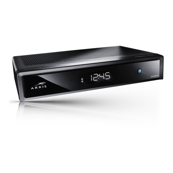
Motorola DCX3520e-M Manuals
Manuals and User Guides for Motorola DCX3520e-M. We have
3
Motorola DCX3520e-M manuals available for free PDF download: Installation Manual, User Manual
Motorola DCX3520e-M Installation Manual (103 pages)
High-Definition DVR
Brand:
Motorola
| Category:
DVR
| Size: 4.57 MB
Table of Contents
Safety & Regulatory Information
4
Important Safety Instructions
4
Important Safety Considerations
4
Fcc Compliance
5
Fcc Declaration of Conformity
6
Software License
7
Table of Contents
9
Tables
11
Figures
11
Introduction
13
Features
14
Tuners
14
Standard Audio/Video Features
14
Figure 1: Front and Rear Views
14
Standard DVR Functionality
15
Table 1: DVR Recording Time Guidelines
15
Standard Data Features
16
Standard Miscellaneous Features
16
If You Need Help
16
Calling for Repairs
17
Overview
18
Front Panel
18
Figure 2: Front Panel
18
Video Format Indicators (Front Panel Display)
19
Rear Panel
20
M-Card
20
Figure 3: Rear Panel
20
Installation
21
Cold Reset Procedure
21
Remote Control Cold Reset
21
Clearing the Hard Drive
22
Video Connection Options
23
Audio Connection Options
24
Table 2: Audio Connection Options
24
Installation Overview
25
Connecting an HDTV - Single Connection for Video/Audio
26
Cable in
26
Hdmi
26
Ieee-1394
26
Figure 4: Connecting an HDTV - Single Connection for Video/Audio
27
Connecting an HDTV - Separate Video/Audio Connections
28
Cable in
28
Component Video (Ypbpr)
28
Audio
28
Figure 5: Connecting an HDTV - Separate Video/Audio Connections
29
Connecting an A/V Receiver - Audio
30
Figure 6: Connecting an A/V Receiver - Audio
31
Connecting a Standard-Definition TV (SDTV)
32
Figure 7: Connecting a Standard-Definition TV (SDTV)
32
Connecting a Standard-Definition TV (SDTV) and VCR/DVD Recorder
33
Figure 8: Connecting a Standard-Definition TV (SDTV) and VCR/DVD Recorder
34
High-Definition DVR DCX3510-M Installation Manual
34
Connecting an A/V Receiver, SDTV, and VCR
35
Figure 9: Connecting an A/V Receiver, SDTV, and VCR
36
Connecting to an External Esata Dvr/Hard Drive
37
Figure 10: Connecting to an External Esata Dvr/Hard Drive
37
Data Device Connections
38
Data Features
38
Figure 11: Examples of Data Devices You Can Connect to the DCX3510-M
38
Operational Check for the Remote Control
39
Table 3: Operational Check Procedures
39
Configuring the User Settings
40
User Settings Menu Main Screen
41
Figure 12: Default User Settings Menu-No HDMI Connection
41
Figure 13: Default User Settings Menu -With HDMI Connection
42
Figure 14: User Settings Menu - Main Menu Screen
42
Table 4: User Settings-Main Menu Field Descriptions
43
Native Mode Settings Screen
46
Figure 15: Native Mode Settings Menu Screen
46
Table 5: Native Mode Settings Field Descriptions
47
Additional HDMI Settings Screen
49
Figure 16: Additional HDMI Settings Screen
49
Table 6: Additional HDMI Settings Field Descriptions
50
Additional Closed Caption Settings Screen
52
Figure 17: Additional Closed Caption Settings Menu Screen
52
Table 7: Additional Closed Caption Settings Field Descriptions
53
Subtitle and DVS Settings Screen
54
Figure 18: Subtitle and DVS Settings Menu Screen
54
Table 8: Subtitle and DVS Settings Field Descriptions
55
Advanced Audio/Video Settings Screen
56
Figure 19: Advanced Audio/Video Settings Menu Screen
56
Graphics Overlaying the Video
57
Table 9: Advanced Audio/Video Settings Field Descriptions
57
Diagnostics
58
Using the Diagnostics
58
General Status
59
Figure 20: Diagnostic Main Menu Screen
59
Figure 21: General Status Diagnostic Screen
59
Table 10: General Status Diagnostic Field Descriptions
60
Figure 22: Example General Status Display (no Error)
60
Purchase Status
61
Figure 23: Purchase Status Diagnostic Screen
61
Table 11: Purchase Status Diagnostic Field Descriptions
62
Figure 24: Front Panel Display for Purchase Status Diagnostic
62
Out-Of-Band (OOB) Status
63
Figure 25: OOB Status Diagnostic Screen
63
Figure 26: Front Panel Display for the OOB Diagnostic
63
Table 12: OOB Diagnostic Field Descriptions
64
Agile OOB Tuner Hunting
65
In-Band Status
67
Figure 27: In-Band Status Diagnostic Screen
67
Figure 28: Front Panel Display for in Band Diagnostic
67
Table 13: In-Band Status Diagnostic Field Descriptions
68
Unit Address
69
Figure 29: Unit Address Diagnostic Screen
69
Figure 30: Front Panel Display of a Unit Address
69
Table 14: Unit Address Diagnostic Field Descriptions
70
Separable Security
71
Table 15: Separable Security Diagnostic Field Descriptions
71
Figure 31: Separable Security Diagnostic Screen
71
Current Channel Status
73
Figure 32: Current Channel Status Diagnostic Screens
73
Figure 33: Current Channel Status Front Panel Displays
73
Table 16: Current Channel Status Diagnostic Field Descriptions
74
RF Modem (Upstream)
76
Figure 34: RF Upstream Modem Diagnostic Screen
76
Figure 35: RF Upstream Modem Front Panel Display
77
Code Modules
78
Table 17: RF Upstream Modem Diagnostic Field Descriptions
78
Figure 36: Code Modules Diagnostic Screen
78
Figure 37: Front Panel Display for Code Modules
79
Table 18: Code Modules Diagnostic Field Descriptions
80
Memory Configuration
82
Audio/Video Status
82
Table 19: Memory Configuration Diagnostic Field Descriptions
82
Figure 38: Memory Configuration Diagnostic Screen
82
Table 20: Audio/Video Status Diagnostic Field Descriptions
83
Figure 39: Audio/Video Status Diagnostic Screen
83
Interface Status
86
Figure 40: Interface Status Diagnostic Screens
86
Table 21: Interface Status Diagnostic Field Descriptions
87
Dvr/Hard Drive Status
88
Figure 41: Dvr/Hard Drive Status Diagnostic Screens
88
Table 22: Dvr/Hard Drive Status Diagnostic Field Descriptions
89
DOCSIS Status
91
Table 23: DOCSIS Status Diagnostic Field Descriptions
91
Figure 42: DOCSIS Status Diagnostic Screens
91
Application Specific Information
94
Table 24: Application Specific Information Diagnostic Field Descriptions
94
Figure 43: Application Specific Information Diagnostic Screen
94
Interactive Status
95
Figure 44: Interactive Status Diagnostic Screen
95
Figure 45: Interactive Status Front Panel Display
95
Table 25: Interactive Status Diagnostic Field Descriptions
96
Connected Home
98
Figure 46: Connected Home Diagnostic Screens
98
Table 26: Connected Home Diagnostic Field Descriptions
99
Troubleshooting
100
Advertisement
Motorola DCX3520e-M Installation Manual (99 pages)
High-Definition DVR
Brand:
Motorola
| Category:
DVR
| Size: 5.36 MB
Table of Contents
Safety & Regulatory Information
3
Important Safety Instructions
3
Important Safety Considerations
3
Fcc Compliance
4
Fcc Declaration of Conformity
5
Software License
6
Table of Contents
8
Tables
10
Figures
10
Introduction
12
Features
13
Tuners
13
Standard Audio/Video Features
13
Figure 1: Front and Rear Views
13
Standard DVR Functionality
14
Table 1: DVR Recording Time Guidelines
14
Standard Data Features
15
Standard Miscellaneous Features
15
Getting Help
15
Calling for Repairs
16
Overview
17
Front Panel
17
Figure 2: Front Panel
17
Video Format Indicators (Front Panel Display)
18
Rear Panel
19
Figure 3: Rear Panel
19
Installation
20
Cold Reset Procedure
20
Remote Control Cold Reset
20
Clearing the Hard Drive
21
Video Connection Options
22
Audio Connection Options
23
Table 2: Audio Connection Options
23
Installation Overview
24
Connecting an HDTV - Single Connection for Video/Audio
25
Cable in
25
Hdmi
25
Figure 4: Connecting an HDTV - Single Connection for Video/Audio
25
Connecting an HDTV - Separate Video/Audio Connections
26
Cable in
26
Component Video (Ypbpr)
26
Audio
26
Figure 5: Connecting an HDTV - Separate Video/Audio Connections
27
Connecting an A/V Receiver - Audio
28
Figure 6: Connecting an A/V Receiver - Audio
29
Connecting a Standard-Definition TV (SDTV)
30
Figure 7: Connecting a Standard-Definition TV (SDTV)
30
Connecting a Standard-Definition TV (SDTV) and VCR/DVD Recorder
31
Figure 8: Connecting a Standard-Definition TV (SDTV) and VCR/DVD Recorder
32
Connecting an A/V Receiver, SDTV, and VCR
33
Figure 9: Connecting an A/V Receiver, SDTV, and VCR/DVD
34
Connecting to an External Esata Dvr/Hard Drive
35
Figure 10: Connecting to an External Esata Dvr/Hard Drive
35
Data Device Connections
36
Data Features
36
Figure 11: Examples of Data Devices You Can Connect to the Dcx3520E-M
36
Operational Check for the Remote Control
37
Table 3: Operational Check Procedures
37
Configuring the User Settings
38
User Settings Menu Main Screen
39
Figure 12: Default User Settings Menu-No HDMI Connection
39
Figure 13: Default User Settings Menu -With HDMI Connection
40
Figure 14: User Settings Menu - Main Menu Screen
40
Table 4: User Settings-Main Menu Field Descriptions
41
Native Mode Settings Screen
44
Figure 15: Native Mode Settings Menu Screen
44
Table 5: Native Mode Settings Field Descriptions
45
Additional HDMI Settings Screen
47
Figure 16: Additional HDMI Settings Screen
47
Table 6: Additional HDMI Settings Field Descriptions
48
Additional Closed Caption Settings Screen
50
Figure 17: Additional Closed Caption Settings Menu Screen
50
Table 7: Additional Closed Caption Settings Field Descriptions
51
Subtitle and DVS Settings Screen
52
Figure 18: Subtitle and DVS Settings Menu Screen
52
Table 8: Subtitle and DVS Settings Field Descriptions
53
Advanced Audio/Video Settings Screen
54
Figure 19: Advanced Audio/Video Settings Menu Screen
54
Graphics Overlaying the Video
55
Table 9: Advanced Audio/Video Settings Field Descriptions
55
Diagnostics
56
Using the Diagnostics
56
General Status
57
Figure 20: Diagnostic Main Menu Screen
57
Figure 21: General Status Diagnostic Screen
57
Table 10: General Status Diagnostic Field Descriptions
58
Figure 22: Example General Status Display (no Error)
58
Purchase Status
59
Figure 23: Purchase Status Diagnostic Screen
59
Table 11: Purchase Status Diagnostic Field Descriptions
60
Figure 24: Front Panel Display for Purchase Status Diagnostic
60
Out-Of-Band (OOB) Status
61
Figure 25: OOB Status Diagnostic Screen
61
Figure 26: Front Panel Display for the OOB Diagnostic
61
Table 12: OOB Diagnostic Field Descriptions
62
Agile OOB Tuner Hunting
63
In-Band Status
65
Figure 27: In-Band Status Diagnostic Screen
65
Figure 28: Front Panel Display for in Band Diagnostic
65
Table 13: In-Band Status Diagnostic Field Descriptions
66
Unit Address
67
Figure 29: Unit Address Diagnostic Screen
67
Figure 30: Front Panel Display of a Unit Address
67
Table 14: Unit Address Diagnostic Field Descriptions
68
Current Channel Status
69
Figure 31: Current Channel Status Diagnostic Screens
69
Figure 32: Current Channel Status Front Panel Displays
69
Table 15: Current Channel Status Diagnostic Field Descriptions
70
RF Modem (Upstream)
72
Figure 33: RF Upstream Modem Diagnostic Screen
72
Figure 34: RF Upstream Modem Front Panel Display
73
Code Modules
74
Table 16: RF Upstream Modem Diagnostic Field Descriptions
74
Figure 35: Code Modules Diagnostic Screen
74
Figure 36: Front Panel Display for Code Modules
75
Table 17: Code Modules Diagnostic Field Descriptions
76
Memory Configuration
78
Audio/Video Status
78
Table 18: Memory Configuration Diagnostic Field Descriptions
78
Figure 37: Sample Memory Configuration Diagnostic Screen
78
Table 19: Audio/Video Status Diagnostic Field Descriptions
79
Figure 38: Audio/Video Status Diagnostic Screen
79
Interface Status
82
Figure 39: Interface Status Diagnostic Screens
82
Table 20: Interface Status Diagnostic Field Descriptions
83
Dvr/Hard Drive Status
84
Figure 40: Dvr/Hard Drive Status Diagnostic Screens
84
Table 21: Dvr/Hard Drive Status Diagnostic Field Descriptions
85
DOCSIS Status
87
Table 22: DOCSIS Status Diagnostic Field Descriptions
87
Figure 41: DOCSIS Status Diagnostic Screens
87
Application Specific Information
90
Table 23: Application Specific Information Diagnostic Field Descriptions
90
Figure 42: Application Specific Information Diagnostic Screen
90
Interactive Status
91
Figure 43: Interactive Status Diagnostic Screen
91
Figure 44: Interactive Status Front Panel Display
91
Table 24: Interactive Status Diagnostic Field Descriptions
92
Connected Home
94
Figure 45: Connected Home Diagnostic Screens
94
Table 25: Connected Home Diagnostic Field Descriptions
95
Troubleshooting
96
Motorola DCX3520e-M User Manual (53 pages)
High-Definition All-Digital Dual Tuner DVR Set-top
Brand:
Motorola
| Category:
DVR
| Size: 4.03 MB
Table of Contents
Safety & Regulatory Information
3
Fcc Compliance
4
Fcc Declaration of Conformity
5
Software License
6
Table of Contents
8
Figures
11
Tables
11
Introduction
11
Overview
11
Features
11
Front Panel
12
Figure 1: Front Panel
12
Rear Panel
13
Figure 2: Rear Panel
13
Operation
14
Turning Power on and off
14
Changing Channels
14
Adjusting the Volume
14
Interactive Program Guide
14
Video Format Indicators (Front Panel Display)
15
Digital Video Recorder (DVR)
16
Using the External DVR Expansion Feature
17
Connecting Your DCX Set-Top
18
Video Connection Options
18
HDMI- HDTV and SDTV
19
Component Video (Ypbpr) - HDTV and SDTV
19
Composite Video - SDTV
19
Connecting an HDTV - Single Connection for Video/Audio
20
Cable in
20
Hdmi
20
Figure 3: Connecting an HDTV - Single Connection for Video/Audio
20
Connecting an HDTV - Separate Video/Audio Connections
21
Cable in
21
DVI
21
Component Video (Ypbpr)
21
Audio
22
Figure 4: Connecting an HDTV - Separate Video/Audio Connections
22
Connecting an A/V Receiver - Audio
23
Figure 5: Connecting an A/V Receiver - Audio
23
Connecting an SDTV
24
Figure 6: Connecting an SDTV
24
Connecting a Standard-Definition TV (SDTV) and VCR/DVD Recorder
25
Figure 7: Connecting a Standard-Definition TV (SDTV) and VCR/DVD Recorder
25
Connecting an A/V Receiver, SDTV, and VCR/DVD Recorder
26
Figure 8: Connecting an A/V Receiver, SDTV, and VCR/DVD Recorder
27
Connecting Your Set-Top to an External Esata DVR
28
Figure 9: Connecting Your Set-Top to an External Esata DVR
28
Data Devices
29
Data Features
29
Figure 10: Data Device Connections
29
On-Screen Graphics
30
Recording Your Connections
31
Configuring the User Settings
32
User Settings Menu Main Screen
33
Figure 11: Default User Settings Menu When no HDMI Connection Is in Place
33
Figure 12: Default User Settings Menu When an HDMI Connection Is in Place
34
Table 1: User Settings Main Menu Field Descriptions
35
Figure 13: User Settings Menu-Main Menu Screen
35
Native Mode Settings Screen
38
Table 2: Native Mode Settings Field Definitions
39
Figure 14: Native Mode Settings Menu Screen
39
Additional HDMI Settings Screen
41
Figure 15: Additional HDMI Settings Screen
41
Table 3: Additional HDMI Settings Field Definitions
42
Additional Closed Caption Settings Screen
44
Table 4: Additional Closed Caption Settings Field Definitions
45
Subtitle and DVS Settings Screen
46
Table 5: Subtitle and DVS Settings Field Definitions
47
Advanced Audio/Video Settings Screen
48
Table 6: Advanced Audio/Video Settings Field Definitions
49
Troubleshooting
50
Advertisement
Advertisement
Related Products
Motorola DCX3400 Series
Motorola DCX3501-M
Motorola DCX3510-M
Motorola DCX700M
Motorola DCH3416
Motorola DCT3412
Motorola DCT6400 Series
Motorola DCH6400 Series
Motorola DCT6412 Phase III
Motorola DCT3416
Motorola Categories
Cell Phone
Two-Way Radio
Baby Monitor
Cordless Telephone
Radio
More Motorola Manuals
Login
Sign In
OR
Sign in with Facebook
Sign in with Google
Upload manual
Upload from disk
Upload from URL