Table of Contents
Advertisement
Quick Links
To w e r
®
Hobbies
guarantees
this kit to be
free from defects
in both material and
workmanship
at
the
date of purchase. This
warranty does not cover any
component parts damaged by
use or modification. In no case
shall Tower Hobbies' liability exceed
the original cost of the purchased kit.
Further, Tower Hobbies reserves the right to
change or modify this warranty without notice.
In that Tower Hobbies has no control over the final
assembly or material used for final assembly, no
liability shall be assumed nor accepted for any damage
resulting from the use by the user of the final
user-assembled
product.
user-assembled product, the user accepts all resulting liability.
If the buyer is not prepared to accept the liability associated with the
use of this product, the buyer is advised to return this kit immediately in
new and unused condition to the place of purchase.
To make a warranty claim send the defective part or item to Hobby Services at
the address below:
Hobby Services • 3002 N. Apollo Dr. Suite 1 • Champaign IL 61822 • USA
Include a letter stating your name, return shipping address, as much contact information
as possible (daytime telephone number, fax number, e-mail address), a detailed description
of the problem and a photocopy of the purchase receipt. Upon receipt of the package the
problem will be evaluated as quickly as possible.
®
© 2015 Tower Hobbies.
A subsidiary of Hobbico, Inc.
I N S T R U C T I O N M A N U A L
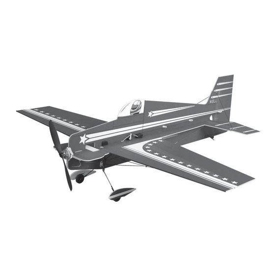
WINGSPAN
33.5 in [850 mm]
RADIO
4 channel
By
the
act
of
using
the
LENGTH
33 in [840 mm]
WING AREA
261 in
2
[16.8 dm
2
]
WEIGHT
5.6 – 6.4 oz [160 –180 g]
READ THROUGH THIS MANUAL
BEFORE STARTING CONSTRUCTION.
IT CONTAINS IMPORTANT INSTRUCTIONS
AND WARNINGS CONCERNING THE
ASSEMBLY AND USE OF THIS MODEL.
WING LOADING
3.1– 3.5 oz/ft
2
[9 –11 g /dm
MOTOR
RimFire
2S or 3S 350 mAh LiPo,
8A –10 A ESC, 8 x 3.8 APC Prop
TOWER HOBBIES
Champaign, Illinois
(217) 398-8970 ext. 5
airsupport@hobbico.com
TOWA2005
2
]
™
250,
Advertisement
Table of Contents

Related Manuals for Tower Hobbies Laser 200 Flatty


Summary of Contents for Tower Hobbies Laser 200 Flatty
-
Page 1: Tower Hobbies
Further, Tower Hobbies reserves the right to change or modify this warranty without notice. READ THROUGH THIS MANUAL In that Tower Hobbies has no control over the final assembly or material used for final assembly, no BEFORE STARTING CONSTRUCTION. liability shall be assumed nor accepted for any damage... -
Page 2: Table Of Contents
INTRODUCTION cause injury to yourself or spectators and damage to property. Thank you for purchasing the Tower Hobbies Laser 200 ARF. 2. You must assemble the Laser according to the instructions. The Laser bridges the gap between heavier, durable “fl at Do not alter or modify the model, as doing so may result in an foamies”... -
Page 3: Tools And Adhesives
you are going to fl y your Laser on a 2S (7.4V) or 3S (11.7V) that doesn’t require soldering connectors is preferred, the battery—of course it can be fl own with both. Powered by a Great Planes SS-12 Brushless ESC is suitable (GPMM1810). 2S battery the Laser is lighter and will fl... -
Page 4: Assembly
ASSEMBLY Assemble the Bottom Half CA GLUING TIPS Assembling lightweight, foam models with CA can occasionally prove to be frustrating, so here are a few suggestions to help you end up with a well-fi nished model free of excess glue, fi ngerprints and smudges: A. - Page 5 ❏ 3. Flip the assembly over. Using care not to lay it back down over any uncured CA on the plastic sheet, wipe any excess CA off the bottom. ❏ 5. Glue the bottom fuselage half to the wing/horizontal fuselage section. As you proceed, use a small builder’s square to make certain the fuselage side is perpendicular.
- Page 6 ❏ 9. Glue the other end of the braces to the vertical part of the fuselage using a builder’s square as you proceed to make sure the fuselage remains vertical. ❏ 7. Lay weights over the structure to hold everything down, making sure the surfaces are fl...
- Page 7 ❏ 11. Glue the bottom motor mount doublers into position — work accurately here as the doublers help set the correct motor right thrust. ❏ 12. Now that most of the structure has been braced and everything is pretty much “set,” temporarily lift the model off the plastic sheet.
-
Page 8: Assemble The Top Half
❏ 4. Fit, then glue the 1mm carbon fi ber top horizontal stab Assemble the Top Half braces into position. Same as before, use a builder’s square to be certain the vertical stab remains vertical and perpendicular to the horizontal stab. ❏... -
Page 9: Hook Up The Ailerons
Hook Up the Ailerons Refer to these photos for the next two steps. While working on the model for the next several steps it will be ❏ handy to have a couple of small boxes or something similar, 7. Fit, then glue the motor mount into position — note that to support the model upside-down. - Page 10 ❏ 2. If using the FlightPower ESC, solder the motor and battery connectors to the leads and use heat-shrink tubing to protect the bullet connectors and solder joints. (As noted in the front of the manual, the JST connector will have to be replaced with a Deans micro.) ❏...
- Page 11 ❏ 6. If you wish to install the optional aileron servo cover, glue it into position now. The cover assists slightly in holding the aileron servo into position and fi lls most of the empty space around the servo simply for appearances, but if your aileron servo is securely glued into position the cover is not necessary.
-
Page 12: Hook Up The Elevator And Rudder
3/8" 1/2" [10mm] [13mm] Elevator Rudder ❏ 1. Center the elevator and rudder servo arms with the radio on and cut off the unused arms. ❏ ❏ 12. With the radio still on, turn the airplane upright. If 2. Install, but do not glue the servos into position. necessary, slide the aileron horns forward or back in the slots in the ailerons to get the ailerons perfectly centered with the fuselage. -
Page 13: Final Assembly
Final Assembly ❏ 1. Now that the structure is completely assembled, go back and reinforce any glue joints where necessary — don’t build up large fi llets of glue — just a drop of thin, foam-safe CA here-and-there where necessary. ❏... -
Page 14: Get The Model Ready To Fly
add stick-on lead ballast to the nose or tail to get it to balance GET THE MODEL READY TO FLY within the range. The farther back the Laser balances the more it will “fl oat” and the more responsive it will be, but if it’s Check the C.G. -
Page 15: Identify Your Model
Ground Check These are the recommended control surface throws: NORMAL RATE 3D RATE Don’t forget to perform an operational ground range check of your radio control system according to the manufacturer’s instructions. Also be certain to set the failsafe function in your Down Down transmitter so in case of loss of signal (or if you inadvertently...
Need help?
Do you have a question about the Laser 200 Flatty and is the answer not in the manual?
Questions and answers