L.B. White Premier TS170 Owner's Manual And Instructions
Tent heaters
Hide thumbs
Also See for Premier TS170:
- Owner's manual and instructions (141 pages) ,
- Owner's manual (34 pages) ,
- Owner's manual and instructions (7 pages)
Table of Contents
Advertisement
Quick Links
Owner's Manual and Instructions
Congratulations!
You have purchased the finest circulating tent heater available.
Your new L.B. White heater incorporates the benefits from the most experienced
manufacturer of heating products using state-of-the-art technology.
We, at L.B. White, thank you for your confidence in our products and
welcome any suggestions or comments you may have...call us, toll-free,
at 1-800-345-7200.
ATTENTION ALL USERS
This heater has been tested and evaluated by C.S.A. International in accordance with
the requirements of Standard ANSI Z83.7 CSA 2.14 and is listed and approved as a
ductable direct gas-fired forced-air construction heater with application for the
temporary heating of buildings under construction, alteration, or repair. Additionally,
this heater has been application reviewed and approved by C.S.A. International for
USA Tent Heating Applications with temporary human occupancy. If you are
considering using this product for any application other than its intended use, then
please contact your fuel gas supplier, or the L.B. White Co., Inc.
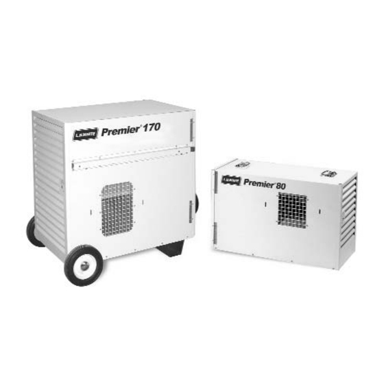
Premier Tent Heaters
MODELS
OUTPUT (Btuh)
TS080
80,000
TS170
170,000
Certification by:
FUEL
Propane Vapor
Withdrawal
or
Natural Gas
150-22665-B
Advertisement
Table of Contents

Related Manuals for L.B. White Premier TS170


Summary of Contents for L.B. White Premier TS170
- Page 1 Your new L.B. White heater incorporates the benefits from the most experienced manufacturer of heating products using state-of-the-art technology. We, at L.B. White, thank you for your confidence in our products and welcome any suggestions or comments you may have...call us, toll-free, at 1-800-345-7200.
- Page 3 Save this Owner’s Manual for future use and reference. ■ Owner’s Manuals and replacement labels are available at no charge. For assistance, contact L.B. White at 800-345-7200. WARNING ■ Proper gas supply pressure must be provided to the inlet of the heater.
-
Page 4: Table Of Contents
Table of Contents SECTION PAGE General Information ..............4 Heater Specifications . -
Page 5: General Information
Have your qualified installer review this manual with you so that you fully understand the heater and how it The L.B. White Co., Inc. has a policy of continuous product functions. improvement. It reserves the right to change specifications and design without notice. -
Page 6: Safety Precautions
Safety Precautions WARNING Asphyxiation H H azard ■ Do not use this heater for heating human living Owner’s Manual, heater dataplate, or contact the L.B. quarters. White Company to determine combustion air ventilation requirements of the heater. ■ Do not use in unventilated areas. ■... - Page 7 Commonwealth of Massachusetts. 11. Always turn off the gas supply to the heater if the 2. All installations and applications of L.B. White heaters heater is not going to be used in the heating of the must meet all relevant local, state and national work space.
-
Page 8: Installation Instructions
Installation Instructions GENERAL 6. Insure that all accessories that ship within the heater WARNING have been removed from inside the heater and installed. Fire a a nd E E xplosion H H azard C C a a n n c c a a u u s s e e p p r r o o p p e e r r t t y y d d a a m m a a g g e e , , s s e e v v e e r r e e i i n n j j u u r r y y o o r r d d e e a a t t h h Check all connections for gas leaks using approved gas leak detectors. -
Page 9: Propane Gas Supply Sizing
If you are in doubt, contact the L.B. White Co., Inc. within a temperature differential of ±3°F. 12. The heater must be installed so as not to interfere 17. -
Page 10: Sliding Handle Assembly Premier 170
SLIDING HANDLE ASSEMBLY Premier 170 The Premier 170 is equipped with sliding handles for FIG. 1 convenient “wheel-barrow” style mobility. Sliding handles are pre-assembled and installed on the heater case. For SLIDING HANDLE shipping purposes, the handles are turned from the required operating position. -
Page 11: Hose Hanger & Regulator Storage Bracket Assembly
HOSE HANGER AND REGULATOR STORAGE BRACKET ASSEMBLY 1. Hose Hanger Assembly: FIG. 4 HEATER CASE Align wire hose hanger to cage nuts on back of SIDE heater. CAGE NUT HOSE HANGER b. Mount the hanger using the 1/4-20 x 3/4 in. bolts and 1/4 in. -
Page 12: Thermostat Assembly
THERMOSTAT ASSEMBLY 1. The remote thermostat has a series tap plug at the FIG. 7 end of the cord. 2. Connect male plug on heater into female side of series tap plug on thermostat. See Fig. 7. 3. Plug male side of series tap plug into grounded, heavy-duty, electrical extension cord. -
Page 13: Unit Diffuser Assembly
UNIT DIFFUSER ASSEMBLY Optional Accessory 09389 (TS080) & 09396 (TS170) 1. Insert the tabs of the diffuser into the vertical slots at FIG. 9 the blower outlet. Push down on diffuser to secure into place. See Fig. 9. 2. Tent side wall material may be layed within channel BLOWER of the dif fuser to give a finished look to the OUTLET... -
Page 14: Connecting Regulator To Propane Gas Supply Cylinder
CONNECTING REGULATOR TO PROPANE GAS CYLINDER ATTENTION 3. Slowly open the cylinder valve by turning counterclockwise. This will prevent lock-up of the excess flow valve built within POL stem. ■ Only use the regulator supplied with the heater. 5. Check all connections with approved leak detector. ■... -
Page 15: Start-Up Instructions
Start-Up Instructions B. V V entilation Connect electrical cord to an approved electrical outlet. When the selector switch is positioned to vent, the Set thermostat to desired room temperature. red light will NOT be on. The fan motor will start, but the igniter will not spark, nor will ignition occur. -
Page 16: Cleaning Instructions
L.B. White Co., Inc. Dataplates, start- up and shut-down instructions and warnings are 4. Regulators can wear out and function improperly. -
Page 17: Service Instructions
Service Instructions GENERAL 1. Close the fuel supply valve to the heater and WARNING disconnect the electrical supply before servicing B B u u r r n n H H a a z z a a r r d d unless necessary for your service procedure. -
Page 18: Igniter And Flame Sensor Assembly
IGNITER AND FLAME SENSOR ASSEMBLY The igniter and sensor assembly is located at the top ATTENTION of the burner casting. See Fig. 17 or 18 depending ■ The igniter and ground rod should be cleaned to on heater model. maintain proper ignition. Remove the two screws securing the mounting Use steel wool or emery cloth. -
Page 19: Testing The Manual Reset High Limit Switches
TESTING THE MANUAL RESET HIGH LIMIT SWITCHES 4. Allow the switch cool down for about a minute before WARNING firmly pressing the reset button on the switch. Fire H H azard ■ Do not operate the heater with the high limit switch 5. -
Page 20: Gas Pressure Checks
Gas Pressure Checks 2. Securely connect a pressure gauge to each pressure WARNING tap. ■ Do not disassemble the gas control valve. 3. Open the fuel supply valves to the heater and reconnect the heater electrical supply. ■ Do not attempt to replace any components of the gas control valve. -
Page 21: Troubleshooting Information
Troubleshooting Information Ventilation M M ode P P roblems Page READ THIS ENTIRE SECTION BEFORE BEGINNING TO TROUBLESHOOT PROBLEMS. A. Motor Does Not Run ......25 B. -
Page 27: Electrical Connection And Ladder Diagram, Ts080
Electrical Connection and Ladder Diagram Model TS080 CAUTION - REFER TO THE HEATER’S ELECTRICAL CONNECTION DIAGRAM WHEN SERVICING TO AVOID WIRING ERRORS & HEATER MALFUNCTION. CHECK FOR PROPER OPERATION AFTER SERVICING. WARNING: THIS HEATER MAY START AT ANY TIME BLACK WHITE CORRECT SPARK MOTOR... -
Page 28: Electrical Connection And Ladder Diagram, Ts170
Electrical Connection and Ladder Diagram Model TS170 CAUTION - REFER TO THE HEATER'S ELECTRICAL CONNECTION DIAGRAM WHEN SERVICING TO AVOID WIRING ERRORS & HEATER MALFUNCTION. CHECK FOR PROPER OPERATION AFTER SERVICING. WARNING: THIS HEATER MAY START AT ANY TIME DIRECT SPARK IGNITION BLACK WHITE MOTOR... -
Page 29: Heater Component Function
Heater Component Function Air Proving Switch Heat Chamber Safety device used to insure that the proper air flow is being Metal “fire box” within the appliance that provides an area achieved before the gas valve is opened. where burner flame mixes with combustion air, thereby providing heat. -
Page 30: Parts Identification
Parts Identification PREMIER 80 PARTS SCHEMATIC... -
Page 31: Premier 80
PREMIER 80 PARTS LIST Item Description Part Number Regulator Propane Gas 08990 Natural Gas 21999 Universal Hose Kit, 10 ft. w/ Adapters 23160 Adapter 1/2 NPT x 5/8 - 18 06655 09309 Screw 09425 Bracket 09760 Valve, Gas Control Propane Gas 22076 Natural Gas 22078... - Page 32 PREMIER 170 PART SCHEMATIC...
-
Page 33: Premier 170
PREMIER 170 PARTS LIST Item Description Part Number Regulator Propane Gas 09911 Natural Gas 09795 Universal Hose Kit, 10 ft. with Adapters 23160 Cap, Hub 07187 Cap, Retaining 01095 Wheel 09160 Spacer 07905 Axle 06421 Base 23082 Cage Nut 07708 Washer 02513 Bolt... -
Page 34: Warranty Policy
12 months from date of shipment from L B. White. found to be defective, L.B. White Co., Inc. will at its option, repair or replace the defective part or heater, with a new part or heater, F.O.B., Onalaska, Wisconsin.
Need help?
Do you have a question about the Premier TS170 and is the answer not in the manual?
Questions and answers